Danfoss-AFD减压阀样本
样本 丹佛斯 电磁阀

DKRCC.PD.BB0.B3.41 / 520H7191
参数表
订货 (续)
电磁阀,型号 EVR 2 − 40 NC/NO
阀体,常闭型(NC)
型号 EVR 2 EVR 3 EVR 6 EVR 10 EVR 15
EVR 20 EVR 22 EVR 25 EVR 32 EVR 40
连接尺寸 可选线圈
型号
喇叭口1)
产品编号 无线圈阀体
钎焊 ODF
[in.] [mm] [in./mm]
[in.]
[mm] 带手动操作
a.c.
1/4
6 032F8056 032F1201 032F1202
—
a.c./ d.c. 1/4
28
EVR 22
a.c.
1 3/8
35
1) 阀体不包含喇叭口螺母。阀体螺栓:
– 1/4 in. 或 6 mm,产品编号 011L1101 – 3/8 in. 或 10 mm,产品编号 011L1135 – 1/2 in. 或 12 mm,产品编号 011L1103 – 5/8 in. 或 16 mm,产品编号 011L1167
—
d.c.
7/8
22
—
—
—
032F1274
a.c.
1 3/8 35
—
032F3267 032F3267
—
a.c./ d.c. 1 1/8
—
—
—
032F2200
a.c./ d.c. — 28
—
—
—
丹佛斯Danfoss截止阀技术手册
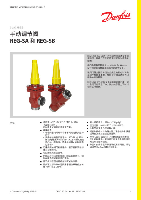
压力设备指令(PED) REG 过滤器符合压力设备指令中规定的欧洲标 准,并带有欧盟强制认证标识。
REG-SA 和 REG-SB 阀门 公称管径 分类目的 类别 第3条第3段 DN = < 25 毫米(1 英寸) DN32-80 毫米 (1¼ - 3 英寸) 液体组 I II III DN100 – 125 毫米(4 - 5 英寸)
R717
A B
0%
25%
50%
䕈ⱘ䕀ࡼ
100% ᠧᓔ
图6
गܟᇣᯊ
(⺙ߚ䩳) 8000 (294)
REG-SA 15-20 和 REG-SB 15-20
∆P = 2 bar (29 psi) ∆P = 1.5 bar (22 psi) ∆P = 1 bar (14 psi) ∆P = 0.5 bar (7 psi)
图2
4
REG-SA 15-20 和 REG-SB 15-20
B
A
2
3 25%
4
5 50%
6
7 75%
8
9 100%
䕈ⱘ䕀ࡼ ᠧᓔ
DKRCI.PD.KM1.A6.41 / 520H7320
© Danfoss A/S (MWA), 2015-01
REG-SA 型和 REG-SB 型手动调节阀 计算和选择(续) 流量系数
© Danfoss A/S (MWA), 2015-01
DKRCI.PD.KM1.A6.41 / 520H7320 3
REG-SA 型和 REG-SB 型手动调节阀 计算和选择 流量系数
Kv (Cv) 0.6 (0.70) 0.5 (0.58) 0.4 (0.46) 0.3 (0.35) 0.2 (0.23) 0.1 (0.12) 0
Danfoss自动差压式平衡阀
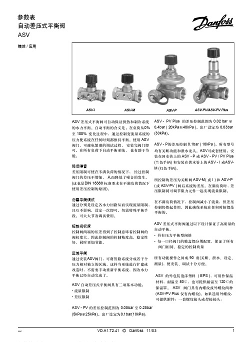
ASV-PV Plus的出厂设定为0.3bar(30kPa), 差压可在0.2bar-0.4bar(20kPa至40kPa)之间 设定。
ASV-PV出厂设定为0.1bar(10kPa),差压可 在0.05bar-0.25bar(5kPa至25kPa)之间设定。
ASV-P的差压为固定值,0.1bar(10kPa)。 ASV-PF DN50的阀门见单独样本。
2,98x1,78 G 1/16
产品编号 003L8155 003L8156 003L8157 003L8158 003L8158 003L8146 003L8147 003L8148 003L8149 003L8149 003L8143
003L8141
003L8145
003L8152
003L8153
ASV - PV 的差压控制范围为 0.05bar 至 0.25bar (5kPa至25kPa)。出厂设定为0.1bar(10kPa)。
SIBC
VD.A1.T2.41 C Danfoss 11/03
1
参数表
订货
SIBC
自动差压式平衡阀 ASV
型号
DN
mk3v/sh
内螺纹 ISO7 / 1
产品编号
15
15
1.6
R p 1/2
003L7 601
20
2.5
R p 3/4
003L7 602
25
4.0
R p1
003L7 603
32
6.3
R p1 1/4
003L7 604
40
10
R p1 1/2
003L7 605
型号
内螺纹 ISO228 / 1
G 1/2A
Danfoss热力膨胀阀样本参数
Danfoss A/S (RC-CM/hbs), 10 - 2002
RK0YP102
3
Introduction
Thermostatic expansion valves for ammonia type TEA
Thermostatic expansion valves regulate the injection of refrigerant liquid into evaporators. Injection is controlled by the refrigerant superheat.
Thermostatic injection valves, type TEAT
Introduction .............................................................................................................................. 11 Materials .................................................................................................................................. 11 Technical data .......................................................................................................................... 11 Identification ............................................................................................................................. 11 Ordering TEAT ......................................................................................................................... 12 Rated capacity in kW ............................................................................................................... 12 Extended capacities in kW ....................................................................................................... 13 Design/Function ....................................................................................................................... 13 Dimensions and weights .......................................................................................................... 14
丹佛斯EVR系列电磁阀样本

EVR is a direct or servo operated solenoid valve for liquid, suction, and hot gas lines with fluorinated refrigerants.EVR valves are supplied complete or as separate components, i.e. valve body, coil and flanges, if required, can be ordered separately.y Complete range of solenoid valvesfor refrigeration, freezing and air conditioning planty Supplied in versions normally closed (NC) and normally open (NO) with de-energized coily Wide choice of coils for AC and DCy Suitable for all fluorinated refrigerants, including flammable refrigerantsy Designed for media temperatures up to 105 °C y MOPD up to 25 bar with 12 W coily Flare connections up to 5/8iny Solder connections up to 2 1/8iny Extended ends on solder versions make the installation easy. It is not necessary to dismantle the valve when soldering iny Available in flare, solder and flange connection versionsFeaturesDet norske Veritas, DNVPressure Equipment Directive (PED) 97/23/EC Low Voltage Directive (LVD) 2006/95/EC Polski Rejestr Statków, Polen Maritime Register of Shipping, MRS Versions with UL approvalcan be supplied to order.ApprovalsData sheet Solenoid valve, types EVR 2 − EVR 40 NC/NOTechnical data1) MOPD (Max. Opening Pressure Differential) for media in gas form is approx. 1 bar greater.2)Min. diff. pressure 0.07 bar is needed to stay open.RefrigerantsR22/R407C, R404A/R507, R410A, R134a, R407A, R23, R32, R290, R600, and R600a. For other refrigerants, contact Danfoss.Special note for R32, R290, R600, and R600a : Use only for system in compliance withstandard EN13463-1. Ignition risk is evaluated inaccordance with standard EN13463-1.Only EVR 2 - EVR 20 with solder connections andwithout manual stem can be applied in systemswith R32, R290, R600, and R600a as the workingfluid. For countries where safety standards are not an indispensable part of the safety system Danfoss recommends the installer to seek third partyapproval for systems containing R32, R290, R600, Note, please follow specific selection criteria stated in the datasheet for these particular refrigerants.Temperature of medium-40 – 105 °C with 10 W or 12 W coil.Max. 130 °C during defrosting.Ambient temperature and enclosure for coil See separate data sheet for coils and ATEX coils.Capacity The capacity of the valve depends on the flow direction, see K v values from the table.The K v value is the water flow in [m 3/h] at a pressure drop across valve of 1 bar, ρ = 1000 kg/m 3.See extended capacity tables later in this datasheet.Table of contentsTechnical data.............................................................................................................................................................................2Rated capacity [kW] .................................................................................................................................................................3Ordering .......................................................................................................................................................................................4Capacity, Liquid .........................................................................................................................................................................7Capacity, Suction .....................................................................................................................................................................11Capacity, Hot gas ....................................................................................................................................................................19Design ........................................................................................................................................................................................40Function.....................................................................................................................................................................................42Material specifications .........................................................................................................................................................43Dimensions and weights .. (45)Data sheet Solenoid valve, types EVR 2 − EVR 40 NC/NORated liquid and suction vapour capacity is based on evaporating temperature t e = -10 °C, liquid temperature ahead of valve t l = 25 °C, pressure drop in valve ∆p = 0.15 bar.Rated hot gas capacity is based on condensing temperature t c = 40 °C, pressure drop across valve ∆p = 0.8 bar, hot gas temperature t h = 65 °C,and subcooling of refrigerant ∆tsub = 4 K.Rated capacity [kW]Data sheet Solenoid valve, types EVR 2 − EVR 40 NC/NOOrdering (continued)EVR solder connections, Normally Closed (NC) - separate valve bodiesData sheet Solenoid valve, types EVR 2 − EVR 40 NC/NOThe normal range of coils can be used for the NO valves, with the exception of the double frequency versions of 110 V,50/60 Hz and 220 V, 50/60 Hz.Ordering (continued)EVR solder connections, Normally Open (NO) - separate valve bodiesValve bodies are supplied without flare nuts. Separate flare nuts:– 1/4 in or 6 mm, code no. 011L1101 – 3/8 in or 10 mm, code no. 011L1135 – 1/2 in or 12 mm, code no. 011L1103 – 5/8 in or 16 mm, code no. 011L1167OrderingEVR flare connections, Normally Closed (NC) - separate valve bodiesSee separate data sheet for coils.The normal range of coils can be used for the NO valves, with the exception of the double frequency versions of 110 V, 50/60 Hz and 220 V, 50/60 Hz.Data sheet Solenoid valve, types EVR 2 − EVR 40 NC/NO Ordering (continued)Separate valve bodies, normally closed (NC)See separate data sheet for coils.Flange setsAccessoriesEVR 15 without manual operation, code no. 032F1224½ in weld flange set, code no. 027N1115+ coil with terminal box, 220 V, 50 Hz, code no. 018F6701See separate data sheet for coils.ExampleCapacities are based on:– liquid temperaturet l = 25 °C ahead of valve, – evaporating temperature t e = -10 °C, superheat 0 K.Correction factorsWhen sizing valves, the plant capacity must be multiplied by a correction factor depending on liquid temperature t l ahead of valve/evaporator.When the corrected capacity is known,the selection can be made from the table.R22/R407CCorrection factors based on liquid temperature t lLiquidCapacities are based on:– liquid temperaturet l = 25 °C ahead of valve, – evaporating temperature t e = -10 °C, superheat 0 K.Correction factorsWhen sizing valves, the plant capacity must be multiplied by a correction factor depending on liquid temperature t l ahead of valve/evaporator.When the corrected capacity is known,the selection can be made from the table.Correction factors based on liquid temperature t lR404A/R507Liquid (continued)Capacities are based on:– liquid temperaturet l = 25 °C ahead of valve, – evaporating temperature t e = -10 °C, superheat 0 K.Correction factorsWhen sizing valves, the plant capacity must be multiplied by a correction factor depending on liquid temperature t l ahead of valve/evaporator.When the corrected capacity is known,the selection can be made from the table.Correction factors based on liquid temperature t lR290Liquid (continued)Data sheet Solenoid valve, types EVR 2 − EVR 40 NC/NOCapacities are based on:– liquid temperaturet l = 25 °C ahead of valve, – evaporating temperature t e = -10 °C, superheat 0 K.Correction factorsWhen sizing valves, the plant capacity must be multiplied by a correction factor depending on liquid temperature t l ahead of valve/evaporator.When the corrected capacity is known,the selection can be made from the table.Correction factors based on liquid temperature t lR600Capacity Liquid (continued)R22/R407CCorrection factorsWhen sizing valves, the evaporator capacity must be multiplied by a correction factor depending on liquid temperature t l ahead of expansion valve.When the corrected capacity is known, the selection can be made from the table.Correction factors for evaporating temperature tlCapacities are based on liquid temperature t l = 25 °C ahead of evaporator. The table values refer to the evaporator capacity and are given as a function ofevaporating temperature t e and pressure drop ∆p across valve.Capacities are based on dry, saturated vapour ahead of valve.During operation with superheated vapour ahead of valve, the capacities are reduced by 4% for each 10 K superheat.Capacity SuctionCapacities are based on liquid temperature t l = 25 °C ahead of evaporator. The table values refer to the evaporator capacity and are given as a function ofevaporating temperature t e and pressure drop ∆p across valve.Capacities are based on dry, saturated vapour ahead of valve.During operation with superheated vapour ahead of valve, the capacities are reduced by 4% for each 10 K superheat.Correction factors based on evaporating temperature t lCorrection factorsWhen sizing valves, the evaporator capacity must be multiplied by a correction factor depending on liquid temperature t l ahead of expansion valve.When the corrected capacity is known,the selection can be made from the table.R134aCapacity Suction(continued)Correction factors based on evaporating temperature t lCorrection factors When sizing valves, the evaporator capacity must be multiplied by a correction factor depending on liquid temperature t l ahead of expansion valve.When the corrected capacity is known,the selection can be made from the table.R404A/R507Capacities are based on liquid temperature t l = 25 °C ahead of evaporator. The table values refer to the evaporator capacity and are given as a function ofevaporating temperature t e and pressure drop ∆p across valve.Capacities are based on dry, saturated vapour ahead of valve.During operation with superheated vapour ahead of valve, the capacities are reduced by 4% for each 10 K superheat.Capacity Suction(continued)Correction factors based on evaporating temperature t lCorrection factorsWhen sizing valves, the evaporator capacity must be multiplied by a correction factor depending on liquid temperature t l ahead of expansion valve.When the corrected capacity is known,the selection can be made from the table.R32Capacities are based on liquid temperature t l = 25 °C ahead of evaporator. The table values refer to the evaporator capacity and are given as a function ofevaporating temperature t e and pressure drop ∆p across valve.Capacities are based on dry, saturated vapour ahead of valve.During operation with superheated vapour ahead of valve, the capacities are reduced by 4% for each 10 K superheat.Capacity Suction(continued)Correction factors based on evaporating temperature t lCorrection factorsWhen sizing valves, the evaporator capacity must be multiplied by a correction factor depending on liquid temperature t l ahead of expansion valve.When the corrected capacity is known,the selection can be made from the table.R290Capacities are based on liquid temperature t l = 25 °C ahead of evaporator. The table values refer to the evaporator capacity and are given as a function ofevaporating temperature t e and pressure drop ∆p across valve.Capacities are based on dry, saturated vapour ahead of valve.During operation with superheated vapour ahead of valve, the capacities are reduced by 4% for each 10 K superheat.Capacity Suction(continued)Correction factors based on evaporating temperature t lCorrection factorsWhen sizing valves, the evaporator capacity must be multiplied by a correction factor depending on liquid temperature t l ahead of expansion valve.When the corrected capacity is known,the selection can be made from the table.R600Capacities are based on liquid temperature t l = 25 °C ahead of evaporator. The table values refer to the evaporator capacity and are given as a function ofevaporating temperature t e and pressure drop ∆p across valve.Capacities are based on dry, saturated vapour ahead of valve.During operation with superheated vapour ahead of valve, the capacities are reduced by 4% for each 10 K superheat.Capacity Suction(continued)Correction factors based on evaporating temperature t lCorrection factorsWhen sizing valves, the evaporator capacity must be multiplied by a correction factor depending on liquid temperature t l ahead of expansion valve.When the corrected capacity is known,the selection can be made from the table.R600aCapacities are based on liquid temperature t l = 25 °C ahead of evaporator. The table values refer to the evaporator capacity and are given as a function ofevaporating temperature t e and pressure drop ∆p across valve.Capacities are based on dry, saturated vapour ahead of valve.During operation with superheated vapour ahead of valve, the capacities are reduced by 4% for each 10 K superheat.Capacity Suction(continued)Hot gas defrostingWith hot gas defrosting it is not normally possible to select a valve from condensing temperature t c and evaporating temperature t e .This is because the pressure in the evaporator as a rule quickly rises to a value near that of the condensing pressure. It remains at this value until the defrosting is finished.In most cases therefore, the valve will be selected from condensing temperature t c and pressure drop ∆p across the valve, as shown in the example for heat recovery.Heat recoveryThe following is given: y Refrigerant = R22/R407Cy Evaporating temperature t e = -30 °C y Condensing temperature t c = 40 °Cy Hot gas temperature ahead of valve t h = 85 °Cy Heat recovery condenser yield Q h = 8 kWThe capacity table for R22/R407C with t c = 40 °C gives the capacity for an EVR 10 as 8.9 kW, when pressure drop ∆p is 0.2 bar.The required capacity is calculated as :Q table = f evaporator x f hot_temperature x Q hThe correction factor for t e = -30 °C is given in the table as 0.95.The correction for hot gas temperature t h = 85 °C has been calculated as 4% which corresponds to a factor of 1.04.Q h must be corrected with factors found: With ∆p = 0.2 baris Q h = 8.71 x 0.95 x 1.04 = 8.6 kW.With ∆p = 0.1 bar, Q h becomes only 6.19 x 0.95 x 1.04 = 6.1 kW.An EVR 6 would also be able to give the required capacity, but with ∆p at approx. 1 bar. The EVR 6 is therefore too small.The EVR 15 is so large that it is doubtful whether the necessary ∆p of approx. 0.1 bar could be obtained.An EVR 15 would therefore be too large.Result: An EVR 10 is the correct valve for the given conditions.Capacity Suction (continued)R22/R407CAn increase in hot gas temperature t h of 10 K, based on t h = t c +25 °C, reduces valve capacity approx. 2% and vice versa.A change in evaporating temperature t e changes valve capacity; see correction factor table below.Correction factorsWhen sizing valves, the table value mustbe multiplied by a correction factor depending on evaporating temperature t e .Correction factors for evaporating temperature teCapacity Hot gasAn increase in hot gas temperature t h of 10 K, based on t h = t c 25 °C, reduces valve capacity approx. 2% and vice versa.A change in evaporating temperature t e changes valve capacity; see correction factor table below.Correction factorsWhen sizing valves, the table value must be multiplied by a correction factor depending on evaporating temperature t e .Correction factors for evaporating temperature teR22/R407C (continued)Capacity Hot gas(continued)Correction factorsWhen sizing valves, the table value must be multiplied by a correction factor depending on evaporating temperature t e .Correction factors for evaporating temperature t eR134aAn increase in hot gas temperature t h of 10 K, based on t h = t c 25 °C, reduces valve capacity approx. 2% and vice versa.A change in evaporating temperature t e changes valve capacity; see correction factor table below.Capacity Hot gas(continued)Correction factorsWhen sizing valves, the table value must be multiplied by a correction factor depending on evaporating temperature t e .Correction factors for evaporating temperature t eR134a (continued)An increase in hot gas temperature t h of 10 K, based on t h = t c 25 °C, reduces valve capacity approx. 2% and vice versa.A change in evaporating temperature t e changes valve capacity; see correction factor table below.Capacity Hot gas(continued)Correction factorsWhen sizing valves, the table value must be multiplied by a correction factor depending on evaporating temperature t e .Correction factors for evaporating temperature teR404A/R507An increase in hot gas temperature t h of 10 K, based on t h = t c 25 °C, reduces valve capacity approx. 2% and vice versa.A change in evaporating temperature t e changes valve capacity; see correction factor table below.Capacity Hot gas(continued)Correction factorsWhen sizing valves, the table value must be multiplied by a correction factor depending on evaporating temperature t e .Correction factors for evaporating temperature teR404A/R507 (continued)An increase in hot gas temperature t h of 10 K, based on t h = t c 25 °C, reduces valve capacity approx. 2% and vice versa.A change in evaporating temperature t e changes valve capacity; see correction factor table below.Capacity Hot gas(continued)Correction factorsWhen sizing valves, the table value must be multiplied by a correction factor depending on evaporating temperature t e .Correction factors for evaporating temperature teR32An increase in hot gas temperature t h of 10 K, based on t h = t c 25 °C, reduces valve capacity approx. 2% and vice versa.A change in evaporating temperature t e changes valve capacity; see correction factor table below.Capacity Hot gas(continued)Correction factorsWhen sizing valves, the table value must be multiplied by a correction factor depending on evaporating temperature t e .Correction factors for evaporating temperature teR32 (continued)An increase in hot gas temperature t h of 10 K, based on t h = t c 25 °C, reduces valve capacity approx. 2% and vice versa.A change in evaporating temperature t e changes valve capacity; see correction factor table below.Capacity Hot gas(continued)Correction factorsWhen sizing valves, the table value must be multiplied by a correction factor depending on evaporating temperature t e .Correction factors for evaporating temperature teR290An increase in hot gas temperature t h of 10 K, based on t h = t c 25 °C, reduces valve capacity approx. 2% and vice versa.A change in evaporating temperature t e changes valve capacity; see correction factor table below.Capacity Hot gas(continued)Correction factorsWhen sizing valves, the table value must be multiplied by a correction factor depending on evaporating temperature t e .Correction factors for evaporating temperature teR290 (continued)An increase in hot gas temperature t h of 10 K, based on t h = t c 25 °C, reduces valve capacity approx. 2% and vice versa.A change in evaporating temperature t e changes valve capacity; see correction factor table below.Capacity Hot gas(continued)Correction factorsWhen sizing valves, the table value must be multiplied by a correction factor depending on evaporating temperature t e .Correction factors for evaporating temperature teR600An increase in hot gas temperature t h of 10 K, based on t h = t c 25 °C, reduces valve capacity approx. 2% and vice versa.A change in evaporating temperature t e changes valve capacity; see correction factor table below.Capacity Hot gas(continued)Correction factorsWhen sizing valves, the table value must be multiplied by a correction factor depending on evaporating temperature t e .Correction factors for evaporating temperature teR600 (continued)An increase in hot gas temperature t h of 10 K, based on t h = t c 25 °C, reduces valve capacity approx. 2% and vice versa.A change in evaporating temperature t e changes valve capacity; see correction factor table below.Capacity Hot gas(continued)Correction factorsWhen sizing valves, the table value must be multiplied by a correction factor depending on evaporating temperature t e .Correction factors for evaporating temperature teR600aAn increase in hot gas temperature t h of 10 K, based on t h = t c 25 °C, reduces valve capacity approx. 2% and vice versa.A change in evaporating temperature t e changes valve capacity; see correction factor table below.Capacity Hot gas(continued)Correction factorsWhen sizing valves, the table value must be multiplied by a correction factor depending on evaporating temperature t e .Correction factors for evaporating temperature teR600a (continued)An increase in hot gas temperature t h of 10 K, based on t h = t c 25 °C, reduces valve capacity approx. 2% and vice versa.A change in evaporating temperature t e changes valve capacity; see correction factor table below.Capacity Hot gas(continued)R22/R407CCapacity Hot gas (continued)An increase in hot gas temperature t h of 10 K, based on t h = t c 25 °C, reduces valve capacity approx. 2% and vice versa.A change in evaporating temperature t e changes valve capacity; see correction factor table below.R134aCapacity Hot gas (continued)An increase in hot gas temperature t h of 10 K, based on t h = t c 25 °C, reduces valve capacity approx. 2% and vice versa.A change in evaporating temperature t e changes valve capacity; see correction factor table below.R404A/R507Capacity Hot gas (continued)An increase in hot gas temperature t h of 10 K, based on t h = t c 25 °C, reduces valve capacity approx. 2% and vice versa.A change in evaporating temperature t e changes valve capacity; see correction factor table below.R32Capacity Hot gas (continued)An increase in hot gas temperature t h of 10 K, based on t h = t c 25 °C, reduces valve capacity approx. 2% and vice versa.A change in evaporating temperature t e changes valve capacity; see correction factor table below.R290Capacity Hot gas (continued)An increase in hot gas temperature t h of 10 K, based on t h = t c 25 °C, reduces valve capacity approx. 2% and vice versa.A change in evaporating temperature t e changes valve capacity; see correction factor table below.R600Capacity Hot gas (continued)An increase in hot gas temperature t h of 10 K, based on t h = t c 25 °C, reduces valve capacity approx. 2% and vice versa.A change in evaporating temperature t e changes valve capacity; see correction factor table below.R600aCapacity Hot gas (continued)An increase in hot gas temperature t h of 10 K, based on t h = t c 25 °C, reduces valve capacity approx. 2% and vice versa.A change in evaporating temperature t e changes valve capacity; see correction factor table below.Design4. Coil16. Armature 18. V alve plate/Pilot valve plate 20. Earth terminal 24. C onnection for flexiblesteel hose 28. Gasket 29. Pilot orifice 30. O-ring 36. DIN plug 37. D IN socket (to DIN 43650) 40. P rotective cap/Terminal box 43. Valve cover 44. O-ring45. Valve cover gasket 49. Valve body73. Equalization hole 80. D iaphragm/Servo piston 83. Valve seat90. Mounting holeNote :The drawings are only representative.4. Coil16. Armature 18. V alve plate/ Pilot valve plate 20. Earth terminal 28. Gasket 29. Pilot orifice 30. O-ring 31. Piston ring 36. DIN plug 37. D IN socket (to DIN 43650) 40. P rotective cap/ Terminal box 43. Valve cover 44. O-ring45. Valve cover gasket 49. Valve body 51. Threaded plug 53. M anual operation spindle 73. Equalization hole 74. Main channel 75. Pilot channel76. Compression spring 80. D iaphragm / Servo piston 83. Valve seat84. Main valve plateEVR 32 and EVR 40 (NC)EVR 25 (NC)Design (continued)Note :The drawings are only representative.Function EVR solenoid valves are designedon two different principles:1. Direct operation2. Servo operation1. Direct operationEVR 2 – EVR 3 are direct operated. The valves open directly for full flow when the armature (16) moves up into the magnetic field of the coil. This means that the valves operate with a min differential pressure of 0 bar.The valve plate (18) is fitted directly on the armature (16).Inlet pressure acts from above on the armature and the valve plate. Thus, inlet pressure and spring force act to close the valve when the coil is currentless.2. Servo operationEVR 6 – EVR 22 are servo operated with a "floating" diaphragm (80). The pilot orifice (29) of stainless steel is placed in the centre of the diaphragm. The pilot valve plate (18) is fitted directly to the armature (16). When the coil is currentless, the main orifice and pilot orifice are closed. The pilot orifice and main orifice are held closed by the armature spring force and the differential pressure between inlet andoutlet sides.When current is applied to the coil the armature is drawn up into the magnetic field and opens the pilot orifice. This relieves the pressure above the diaphragm, i.e. the space above the diaphragm becomes connected to the outlet side of the valve. The differential pressure between inlet and outlet sides then presses the diaphragm away from the main orifice and opens it for full flow. Therefore a certain minimum differential pressure is necessary to open the valve and keep it open. For EVR 6 – EVR 22 valves this differential pressure is 0.05 bar.When current is switched off, the pilot orifice closes. Via the equalization holes (73) in the diaphragm, the pressure above the diaphragm then rises to the same value as the inlet pressure and the diaphragm closes the main orifice.EVR 25, EVR 32 and EVR 40 are servo operated piston valves. The valves are closed with currentless coil. The servo piston (80) with main valve plate (84) closes against the valve seat (83) by means of the differential pressure between inlet and outlet side of the valve and the force of the compression spring (76). When current to the coil is switched on, the pilot orifice (29) opens. This relieves the pressure on the piston spring side of the valve. The differential pressure will then open the valve. The minimum differential pressure needed for full opening of the valves is 0.2 bar. EVR (NO) has the opposite function to EVR (NC), i.e. it is open with de-energised coil.EVR (NO) is available with servo operation only.Material specifications EVR 2 – EVR 25Note:The drawings are only representative.Material specifications (continued)EVR 32 – EVR 40Note :The drawing is only representative.With DIN plugs coilWith cable connection coilNet weight of coil 10 W: approx. 0.3 kg12 and 20 W: approx. 0.5 kgWith terminal box coilDimensions [mm] and weights [kg]EVR 2 – EVR 6 NC/NO, solder connection For 3D models, visit /products/categories/Note :The drawings are only representative.。
丹佛斯Danfoss动态压差平衡阀ASV参数表-水力平衡
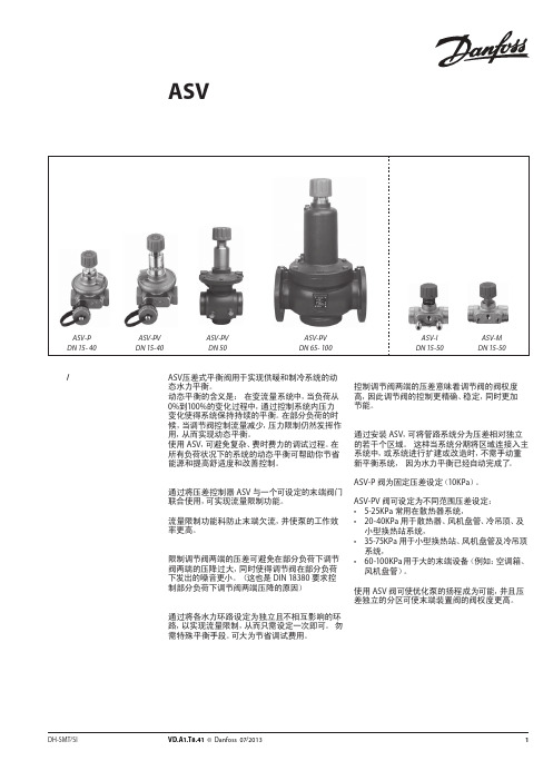
图 4 ASV用于地板采暖系统中分集水器前
ASV 阀用于地板采暖系统。为实现对每个环路的 流量限制,应将带有预设定的分集水器与 ASV-PV 阀提供的恒定压差控制配合使用。或者通过使用
具有设定功能 ASV-I 实现对整个分集水器的流量 限制。
如需不同的设定压差,ASV-PV 的设定压差具有数 个的可选范围。由于尺寸紧凑,ASV 动态压差平衡 阀易于安装于挂墙的分集水器安装盒内。
型号
备注
螺纹尾管(1 件)
焊接尾管(1 件)
连接至管道 R½ R¾ R1 R 1¼ R 1½
R2
DN 15 DN 20 DN 25 DN 32 DN 40
DN 50
注意: ASV-PV DN 50 (2½”) 和 ASV-I/M DN 50 (2¼”) 的接头口径不同。 1) 与 ASV-PV DN 50 阀配套使用 2) 与 ASV-I 和 ASV-M DN 50 配套使用。
ASV-P 阀为固定压差设定(10KPa)。
ASV-PV 阀可设定为不同范围压差设定: • 5-25KPa 常用在散热器系统, • 20-40KPa 用于散热器、风机盘管、冷吊顶、及
小型换热站系统, • 35-75KPa 用于小型换热站、风机盘管及冷吊顶
系统, • 60-100KPa 用于大的末端设备(例如:空调箱、
22
VD.A1.T8.41 © Danfoss 07/2013
DH-SMT/SI
DH-SMT/SI
VD.A1.T8.41 © Danfoss 07/2013
3
参数表 描述 / 应用 (续)
动态压差平衡阀 ASV
参数表
保温材料
图 +5 ASV 用于风机盘管系统
丹佛斯Danfoss静态平衡阀MSV-BD参数表-水力平衡

2
VDB4C341 © Danfoss03/2012
HEC-HB
参数表
静态平衡阀 LENO™ MSV-BD
压紧连接件(用于外螺纹阀) 钢/铜管 G ¾ x 15 G ¾ x 16 G ¾ x 18 G 1 x 18 尺寸 产品编号 013G4125 013G4126 013G4128 013U0134
5
5.封条—保护设定值(如图所示)。
测量
当水流过 MSV-BD调节阀时, 使用丹佛斯PFM 3000/4000 或其它测量仪可以对其流量进行测 量。 LENO™ MSV-BD调节阀提供两个测试头,适 合直径3mm的测试探针。支架成对,可以同时 连接这两个测试头。 注意:如使用非丹佛斯测量仪器,需对结果进 行修正,相关信息请联系丹佛斯。 测量流量的过程: 1.选择流量测量 2.选择阀门品牌 3.选择阀门类型和尺寸 4.输入预调节值 5.连接阀和测量仪仪器 6.校准静态压力 7.测量流量
kv = Qm3/h √∆pi bar = 2.0 √0.20 = 4.5 m3/h
Leno™ MSV-BD ∆p r ∆p m
7
∆p i
M
∆p a
丹佛斯Danfoss生活热水循环系统多功能恒温阀MTCV-水力平衡
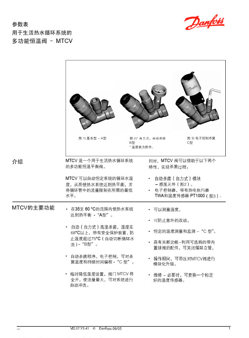
多功能恒温阀 - MTCV
50 ˚C下 在 35 ˚C下
在 60˚C下
流 量 水 温 温 度 ˚C
预设
预设
预设
预设
预设
预设
水温 ˚C
流量温度 ˚C
B型 C型
数据表 计算举例
多功能恒温阀 - MTCV
8 个立管进行计算。
VD.57.X1.02
•
q1 =10
*
*
- 管路的尺寸 - 绝热层的材料 - 装管子处的环境温度 - 绝热层的效率和条件
•
Tsup = 55 °C
•
∆T= 5 K
•
•
l = 10 m
•
I 基本操作
• 每个立管中热量损失的计算
Qr
Qh
Qr = l立管x q = (10+10) x10 = 200 m
Qh= l 水平 x q = 10 x 10= 100 m
•表3
立管
立管中 Qr
顶部 Qh
热量损失 每一部分的 总的损失
ΣQ 总
阀 – 基本型A型
产品编号
阀体 ................................................Rg 5 O型密封圈 ...................................EPDM
. 不锈钢
高温杀菌模块 -B型
描述
产品编号
ESMB PT1000用插座
CCR2控制器
• 模块化升级。
• 好的温度传感器。
数据表 功能
多功能恒温阀 - MTCV
1-A型。
当水温比设定值高 5°
MTCV 是一种自力式比例控制的恒温控制