泰克示波器MSO5000
示波器品牌对比

500MHz 350MHz 200MHz 200MHz 200MHz
模拟带宽
4 4 4 4 2
通道数
ZDS1104 100M
4
采样率
4G 4G 4G 2G 2G
采样率
1G
存储深度 波形刷新率 解码种类 FFT点数 测量统计项 FIR滤波器
250Mpts
>330Kwfms/s 41种
4M
54种
有
65999
• MSO/DPO70000:带宽:4 GHz -33 GHz;记录长度:多达 1G 点;通道数:4 条模拟通道,16 条数字 通道 (MSO);采样率:高达 100 Gs/s。
• DPO70000SX:带宽:13 GHz - 70 GHz;记录长度:多达 1G 个点;模拟通道:1 至 16;采样率:高 达 200 GS/s。
4
模拟带宽 通道
ZDS3024 200MHz
4
采样率
4G 4G 4G
采样率
2G
存储深度
波形刷新率
协议解码种 类
FFT点数
512Mpts
>1Mwfms/s 41种
4M
测量统计项 FIR滤波器 市场价格
54种
有
71999
512Mpts
>1Mwfms/s 41种
4M
54种
有
53999
512Mpቤተ መጻሕፍቲ ባይዱs
>1Mwfms/s 41种
MSO/DPO5000:杰出的信号采集性能和分析功能,高达 2 GHz 的带宽和 10 GS/s采样率,同时还具有高级 分析和数学运算功能.示波器上运行基于 Windows® 的分析软件
示波器与探头校准
本文所述内容对您的仪器进行设置。
2
如何选择合适的探头
三个考虑决定使用探头的类型:
1、评估待测信号类型(电流/电压)
– 电流探头测电流,高压探头测上百伏特信号,一般探头测中间电压信号
2、评估待测信号频率
– 跟示波器带宽选择类似,3倍/5倍于信号最高基频
32
机械损坏之二
使用非正式的探针
例子:使用非正式的短探针插入P6245探头中,造成探针无法拔 出。
使用探针不当
例子:用探针来刮开PCB板上的阻焊涂层(绿油),造成探针根部 的塑料开裂
33
电气损坏之一:EOS
探头长期探测超出量程的信号
例子:长期使用P6243探头测试12V电源上电波形。过了一段时 间,探头前端剧烈发热,损坏探头。
电应力过度(EOS-Electrical Overstress )损伤:探头无法工作
静电放电(ESD-Electro Static Discharge )损伤:探头无法工作
31
机械损坏之一
探测时给探头施加过度的压力
例子:P7330探头的绿色标签“Read This First”明确指出,探 头必须垂直接触DUT,且压力不可超过3.0lbs(1.36kg)。
,开机半个小时左右热机后,然后直接点击SPC就可以了,这个就 是示波器的校准,大概需要一刻钟;后面有详细的操作说明。 果两次之后还是不在零电平,那么这时候就需要联系我们客服中 心电话(400 820 5835)咨询校准事宜。
如果做完一次之后信号线还不是在零电平,可以再试着做一次;如
8
示波器SPC校准:SPC状态的含义
5
泰克500MHz 10X探头用户手册说明书

Revision A500MHz 10X ProbesThe P6139B &P5050B probes are high impedance,passive probes that are designed for use with Tektronix ground-referenced oscilloscopes,including theDPO/MSO/TDS 3000/4000/5000/7000series oscilloscopes.Both probes have a bandwidth of >500MHz and 10X attenuation.The P6139B probe has a compensation range of 8to 18pF,while the P5050B probe has a compensation range of 15to 22pF.Connecting the Probe to the OscilloscopeConnect the probe to the oscilloscope as shownbelow.Compensating the ProbeDue to variations in oscilloscope input characteristics,the low-frequency compensation of the probe may need adjustment after moving the probe from one oscilloscope channel to another.If a 1kHz calibrated square wave displayed at 1ms/division shows signi ficant differences between the leading and trailing edges,perform the following steps to optimize low-frequency compensation:1.Connect the probe to the oscilloscope channel that you plan to use for your measurements.2.Connect the probe to the probe compensation output terminals on the oscilloscope frontpanel.WARNING.To avoid electric shock,only connect to the Probe Comp signal on the oscilloscope when making this adjustment.To avoid electric shock,only use the insulated adjustment tool when making compensation adjustments.3.Push AUTOSET or otherwise adjust your oscilloscope to display a stable waveform.4.Adjust the trimmer in the probe until you see a perfectly flat-top square wave on the display.(Seeillustration.)Standard AccessoriesThe accessories included with the probe are shownbelow.WARNING.To avoid electric shock when using the probe or accessories,keep fingers behind the finger guard of probe body and accessories.To reduce risk of shock,verify that the ground lead and ground spring are fully mated before connecting the probe to the circuit under test.ItemDescriptionUniversal IC CapUse this cap to prevent shorting the probe tip between IC pins.Press the cap on the probe tip until it snaps on,and then spin the cap to expose the probe tip toward the IC lead.Reorder Tektronix part number013-0366-xxHook tipPress the hook tip on the probe tip and then clamp the hook on the circuit.Rating:300V CAT II Reorder Tektronix part number013-0362-xxColor bandsUse these bands to identify the oscilloscope channel at the probe head.Reorder Tektronix part number 016-0633-xx (5pairs)ItemDescriptionGround lead,with alligator clipAttach the lead to the probe head ground and then to your circuit ground.Reorder Tektronix part number196-3521-xxGround springThis spring minimizesaberrations on high frequency signals caused by ground path inductance,giving you measurements with good signal fidelity.Attach the spring to the ground band on the probe tip.Bend the spring in or out,up to ~0.75in.Reorder Tektronix part number016-2028-xxAdjustment toolUse only this insulated tool for compensation adjustments.Reorder Tektronix part number 003-1433-xxOptional AccessoriesThe accessories shown below are available for the probes and are rated ≤30V unless indicated otherwise.Accessory Part number MicroCKT Test Tip206-0569-xx Micro Hook TipRating:300V CAT II 013-0363-xx BNC to Tip Adapter,Unterminated 013-0367-xx Circuit Board Test Point/PCB Adapter 016-2016-xx Chassis-Mount Probe Test Jack 131-4210-xx 6”Clip-on Ground Lead 196-3198-xx 12”Alligator Ground Lead 196-3512-xx Ground Spring,Short016-2034-xxP6139B &P5050B500MHz 10X Passive Probes Instructions*P071271000*071-2710-00Revision AReplacing the Probe TipOrder Tektronix part number 206-0635-xx (P6139B)or 206-0636-xx (P5050B).The insulator sleeve,part number 204-1226-xx,is reorderable and is common to bothprobes.WARNING.Only quali fied service personnel should replace the probe tip.Disconnect the probe before servicing.After replacing the tip,securely tighten the insulator sleeve before using theprobe.Speci ficationsTable 1:Electrical and mechanical speci ficationsCharacteristic Speci fication BandwidthDC to 500MHz (–3dB)System attenuation accuracy 10:1±0.5%@DC Compensation range P6139B:8pF–18pF P5050B:15pF–22pF System input resistance 10M Ω±0.5%@DC System input capacitance P6139B:<8pF P5050B:<11pF Propagation delay ~6nsMaximum tip input voltage 300V RMS CAT II and DC Cable length1.3mTable 2:Environmental speci ficationsCharacteristic DescriptionTemperature Operating Nonoperating –15°C (+5°F)to +65°C (+149°F)–62°C to +85°C (–80°F to +185°F)Humidity Operating5%to 95%relative humidity (%RH)up to +30°C,5%to 75%RH above +30°C up to +65°C.NoncondensingNonoperating 5%to 45%RH above +65°C up to +85°C.NoncondensingAltitude Operating Nonoperating3.0km (10,000ft)maximum 15km (50,000ft)maximumTable 3:Certi fications and compliancesCharacteristic Description ECDeclaration ofConformityCompliance was demonstrated to the following speci fication as listed in the Of ficial Journal of the European Communities:Low Voltage Directive 2006/95/EC:EN61010-031:2008CAT III:Distribution-level mains,fixed installation CAT II:Local-level mains,portable equipmentMeasurement CategoryProductExamplesCAT I:Circuits not directly connected to mains Characteristic Description Pollution Degree 2Do not operate in environments where cond–uctive pollutants may be present (as de fined in IEC 61010-1).Rated for indoor use only.Additional Safety StandardsUL61010-031;2010CAN/CSA C22.2No.61010-031:07/A1:2010IEC61010-031;IEC61010-031/A1:2008Equipment Recycling.This product complies with the European Union’s requirements according to Directive 2002/96/EC on waste electrical and electronic equipment (WEEE).For more information about recycling options,check the Support/Service section of the Tektronix Web site ().Safety SummaryReview the following safety precautions to avoid injury and prevent damage to this product or any products connected to it.To avoid potential hazards,use this product only as speci fiing the probe or accessories in a manner not speci fied could result in a shock or fire hazard.To Avoid Fire or Personal InjuryGround-Referenced oscilloscope use.Do not float the reference lead of this probe when using with ground referenced oscilloscopes (for example,DPO,MSO,and TDS series oscilloscopes).The reference lead must be connected to earth potential (0V).Connect and disconnect properly.Connect the probe output to the measurement instrument before connecting the probe to the circuit under test.Disconnect the probe input and the probe reference lead from the circuit under test before disconnecting the probe from the measurement instrument.Avoid electric shock.To avoid injury or loss of life,do not connect or disconnect probes or test leads while they are connected to a voltage source.Observe all terminal ratings.To avoid fire or shock hazard,observe all ratings and markings on the product.Consult the product manual for further ratings information before making connections to the product.Avoid electric shock.When using probe accessories,never exceed the lowest rating of the probe or its accessory,whichever is less,including the measurement category and voltage rating.Avoid electric overload.To avoid injury or fire hazard,do not apply potential to any input,including the reference inputs,that varies from ground by more than the maximum rating for that input.Avoid exposed circuitry and do not operate withoutcovers.Do not touch exposed connections and components when power is present.Inspect the probe and accessories.Before each use,inspect probe and accessories for damage (cuts,tears,defects in the probe body,accessories,cable jacket,etc.).Do not use if damaged.Do not operate in Wet/Damp conditions.Do not operate in an explosive atmosphere.Keep product surfaces clean and dry.Safety Terms and Symbols Terms in This Manual.These terms may appear in thismanual:WARNING.Warning statements identify conditions or practices that could result in injury or loss oflife.CAUTION.Caution statements identify conditions or practices that could result in damage to this product or other property.Symbols on the product.These symbols may appear on theproduct:Contacting TektronixWeb site: Phone:1-800-833-9200Address:Tektronix,Inc.Department or name (if known)14200SW Karl Braun Drive P.O.Box 500Beaverton,OR 97077USAEmail:*************************Warranty InformationFor warranty information,go to /warrantyCopyright ©Tektronix,Inc.All rights 。
Agilent 5000 系列便携式示波器 说明书

Agilent 5000系列便携式示波器技术资料新一代便携式示波器2通用示波器的新标准• 带宽为100 MHz 、300 MHz 和 500 MHz • 2 个或 4 个通道• MegaZoom III 存储与显示技术 • 深达 1 Mpts 的采样存储器 (第4页)• 高达每秒 100,000 个波形的 实时捕获速率 (第5页) • 256 级亮度(辉度)高清晰 XGA (1024 x 768) 显示• 高达12位的垂直分辨率,即使 单次采样也能达到这一水平 (第 7 页)• 完备的标准接口 - 标配 (第 6 页) • USB (3 个端口) • LAN • GPIB • XGA 显示输出• 包括web 浏览器在内,全面实现 远端遥控功能 • 符合 LXI C 类仪器标准• 11种可选语言的用户手册 和示波器在线帮助• 安全环境选项传统台式示波器对于描述您已知的问题非常好。
Agilent 公司MegaZoom III 的深存储器和高捕获速率帮助您找出未知问题。
3适用于所有示波器使用者的前沿技术5000 系列示波器采用了与我们的高性能台式和实验室级示波器相同的第三代 MegaZoom III 技术模块 - 快速响应的深存储器、极小的“死区”时间、高捕获速率、类似模拟示波器的显示系统,我们把这些技术结合在一个紧凑的机箱内,但价格却与采用过去技术的示波器类似。
如果您最近还没有购买过Agilent 示波器,为什么不现在就考虑买一台呢?型号带宽 (MHz)通道数最高取样速度存储深度 捕获速率DSO5012A 100 2 2 GSa/s DSO5014A 100 4 2 GSa/s DSO5032A 300 2 2 GSa/s 最高达 1 Mpts 1 (第 4 页) 最高达每秒 100,000个波形(第 5 页)DSO5034A 300 4 2 GSa/s DSO5052A 500 2 4 GSa/s 2 DSO5054A50044 GSa/s 21 当交叉使用两个通道时获得的最深存储深度2当交叉使用两个通道时获得的最高采样率行业领先的客户支持作为全球领先的测试与测量厂商,Agilent 公司拥有最大的销售工程师、应用工程师、支持工程师与技术人员网络。
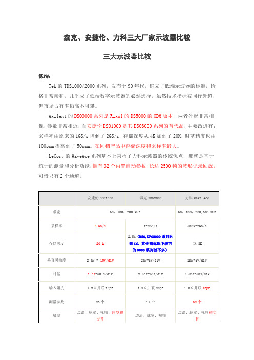
泰克安捷伦力科示波器对比
RS-232/UART, FlexRay
边沿,毛刺,宽度,窗口,跌落,间隔,欠幅脉冲,转换速率或码型,TV,I2C, SPI, UART-RS232, CAN, LIN, FlexRay
力科则是传承了其一贯强悍的统计测量和数学运算分析功能。
安捷伦7000
泰克TDS5000B(win系统)/ DPO 4000
力科WR Xi /WR XS
带宽
100MHz,350MHz,500MHz,1GHz
400,600,1G,2GHz/200,400,600,1GHz
采样率
2GS/s - 4GS/s
安捷伦DSO 90000A
泰克DPO TDS70000B
力科WM 8 Zi
带宽
2.5,4,6,8,12,(DSP)13GHz
4,6,8,12.5,16,(DSP) 20GHz
4,6,8,13,16,(DSP)20,25,30GHz
采样率
20GS/s - 40GS/s
25 GS/s - 50 GS/s
拥有独门的实时采样和荧光技术
测量和运算分析功能最为丰富
安捷伦
MSO 7104A
MSO 6104A(电池选件,可供电2小时)
MSO 9104A(windows系统)
带宽
1 GHz
上升时间
350ps
253ps
采样率
4 GS/s
20 GSa/s
模拟通道
4个
显示
12.1英寸
6.3英寸
15英寸触摸屏
存储深度
8 M
RS-232/UART
泰克示波器选型手册

可视触发 – 迅速找到关心的信号
模拟带宽 4 GHz 4 GHz 6 GHz 6 GHz 8 GHz 8 GHz 12.5 GHz 12.5 GHz 16 GHz 16 GHz 20 GHz 20 GHz 23 GHz 23 GHz 25 GHz 25 GHz 33 GHz 33 GHz
模拟采样率——2/4 个通道 25 GS/s 25 GS/s 25 GS/s 25 GS/s 25 GS/s 25 GS/s 100 GS/s / 50 GS/s 100 GS/s / 50 GS/s 100 GS/s / 50 GS/s 100 GS/s / 50 GS/s 100 GS/s / 50 GS/s 100 GS/s / 50 GS/s 100 GS/s / 50 GS/s 100 GS/s / 50 GS/s 100 GS/s / 50 GS/s 100 GS/s / 50 GS/s 100 GS/s / 50 GS/s 100 GS/s / 50 GS/s
码型锁定触发功能使示波器能够以出色的时基精度同步采集 长串行测试码型,为 NRZ 串行码型触发增加了额外的维度。 码型锁定触发功能可以用于从长串行数据码型中去除随机抖 动。 可以考察每个特定跳变位的影响,而且模板测试时还可 以使用平均功能。 码型锁定触发功能支持高达 6.25 Gb/s 的 NRZ 串行数据流,在 MSO70000 系列仪器上为标配,在 DPO70000 系列上作为选项 ST6G 提供。
全新RIGOL VS5000系列虚拟示波器推动MSO混合测试实践应用

( 罗门哈斯 公 司与 S KC公 司
供稿 )
其发 展道路 上迈 出 的重要 一 步 ,罗 门 哈斯 电子材 料 公 司 ”
全 新 RI GOL V 5 0 S 0 0系 列 虚 拟 示 波 器 推 动 MS 混 合 测 试 实践 应 用 O
日 , 京 普 源 精 电科 技 有 限 公 司 ( I ( 提 出的 前 北 RG)) I
副 总裁兼 事业 部 总监 Yi o ak博 士 表示 。“ 司 目 Hy n P i 公
H a 显示 薄膜公 司 (K H a i l i ) as S as s a Fl 已于 本周 正 D p y ms
式投入运 营 。合 资公 司 的 总部 位 于韩 国 , 责开 发 、 造 负 制
业部 。 “ KC Ha s 司的成 立 是罗 门哈 斯 电子 材料 公 司 在 S a公
离子显示器专用显示薄膜系列产品、 颜色分散体及 L D C
彩 色光 阻主要 配料 。除了这些 薄膜 及材料 , 罗门 哈斯平 板 显 示器技 术事 业部还 开发 和制造 T T光 致抗蚀 剂及 彩色 F
前 正大举 进军平 板显示 器业 务 , 相信凭借 我们 的专 门技术
和 新近 并 购 的柯 达 光学 机 能 膜 事 业 部 的销 售 渠 道 以 及 S a KC Has的生产 能力 , 肯定 会 令 公 司在这 个 不断 发展 的
及销售 平板显 示器行业 所需 的高级 光学 机能膜产 品 。 S C H a 的成 立 对 于 罗 f 哈斯 电 子材 料 公 司来 说 K as 、 _ 】
具有重 大里程 碑意 义 , 也是 其平板 显示 器技术 事业 部 业务
市场 中处 于非 常有利 的竞 争地 位 。 ” 公 司将开 发 、 制造及 销售 的产品包 括液 晶 ( C ) 等 L D及
示波器测量电流探头手册 - tektronix说明书

AC/DC Current Measurement SystemsTCPA300, TCP312A, TCP305A, TCP303, TCPA400, TCP404XL DatasheetThe TCP300 and TCP400 Series AC/DC current measurement family is a highly advanced current measurement system for today's current measurement needs. When connected to Tektronix oscilloscopes with TEKPROBE Level II, TekConnect (w/ TCA-BNC), or TekVPI (w/ TPA-BNC)interfaces, current measurements and calculations are simple and easy.Key performance specificationsDC - 100 MHz, Current Probe Amplifier (TCPA300) uses:DC - 100 MHz, 30 A DC (TCP312A)DC - 50 MHz, 50 A DC (TCP305A)DC - 15 MHz, 150 A DC (TCP303)DC - 50 MHz, Current Probe Amplifier (TCPA400) Uses:DC - 2 MHz, 750 A DC 1 (TCP404XL) (500 A DC Continuous)Key featuresAutomatic scaling and units 2 - Oscilloscope on-screen readout of magnitude and amps reduces measurement errors with no more handcalculationsAC/DC input couplingLow insertion impedance reduces device under test loadingSplit-core construction allows easy circuit connectionStatus indicators provide visual operating status and notification of potential error conditions - degauss, probe open, overload, notterminated into 50 Ω, noncompatible probe typeLow DC drift and noise allows improved low-level currentmeasurements3rd party safety certificationApplicationsDevelopment and analysis solutions for designers, installers, and service personnel in telecom, data comm, computer, andsemiconductor power electronics environments for:Power supplies (switching and linear)Semiconductor devices (SCRs, IGBTs, MOSFETs, CMOS, BJTs)Power inverters/convertersElectronic ballastsIndustrial/consumer electronicsMobile communications (phone, satellite, relay stations)Motor drivesTransportation systems (electronic vehicles, electric trains,locomotives, avionics)Meets today's AC/DC current measurement applicationsThe TCPA300 amplifier, when used with TCP312A, TCP305A, or TCP303probes, provides a wide range of current measurement capability and spans the gap between low-level milliamp measurements to very high current levels. These three probes provide current measurement capabilities of 30 A, 50 A, and 150 A DC continuous. For even higher current levels, the TCPA400 amplifier with the TCP404XL current probe measures 500 A DC continuous and 750 A DC continuous, derated with duty cycle.Higher-frequency performance is available with the TCP312A w/TCPA300providing ≥100 MHz bandwidth and a maximum current of 30 A DC.1Derated with duty cycle2Requires a TDS TEKSCOPE oscilloscope or a TekConnect oscilloscope with TCA-BNC adapterMeasurement errors and manual calculations are now a thing of the pastWith this new series of current measurement tools, automatic control and on-screen scaling and units is provided for users of Tektronix TDS3000, TDS500, TDS600, TDS700, TDS5000, TDS6000, and TDS7000B series oscilloscope systems (the DPO3000, MDO/MSO/DPO4000, MSO/DPO5000, and DPO7000 series oscilloscopes, the TPA-BNC adapter is required).The TCP300/TCP400 current measurement systems seamlessly integrate with your TDS series oscilloscope.Even non-TEKPROBE systems can use the TCPA300/400 series to make proper current measurements by simply multiplying the measured output voltage on the oscilloscope by the TCPA300/400 series range setting.SpecificationsAll specifications are guaranteed unless noted otherwise. All specifications apply to all models unless noted otherwise. Model overviewDatasheetCharacteristicsMaximum current ratingsHigh-current sensitivityLow-current sensitivityRange 1 A/V 5 A/V 5 A/V N/A DC (continuous) 5 A 25 A 25 A N/A RMS (sinusoidal) 3.5 A 17.7 A 17.7 A N/A Peak50 A50 A500 AN/APhysical characteristicsAmplifiersProbesMaximum conductor sizeCable length1.5 m (60 in)1.5 m (60 in)2 m (78.7 in)8 m (315 in)EMC environment and safetySafety complianceElectromagnetic compatibility,amplifiers onlyEC Council Directive 89/336/EEC, FCC Part 15, Subpart B Class A, AS/NZS 2064.1/2.AC/DC Current Measurement SystemsTemperatureOperating0 °C to +50 °C (32 °F to 122 °F)Nonoperating-40 °C to +75 °C (-40 °F to 167 °F)HumidityOperating5% to 95% R.H. to +30 °C (86 °F)5% to 85% R.H. +30 °C to +50 °C (86 °F to 122 °F)Nonoperating5% to 95% R.H. to +30 °C (86 °F)5% to 85% R.H. +30 °C to +75 °C (86 °F to 167 °F)AltitudeOperating2000 m (6800 ft.) maximumNonoperating12,192 m (40,000 ft.) maximumOrdering informationModelsProbesTCP312A Probe AC/DC current, DC to 100 MHz; 30 A DC (Requires TCPA300 amplifier)TCP305A Probe AC/DC current, DC to 50 MHz; 50 A DC (Requires TCPA300 amplifier)TCP303 Probe AC/DC current, DC to 15 MHz; 150 A DC (Requires TCPA300 amplifier)TCP404XL Probe AC/DC current, DC to 2 MHz; 500 A DC (750 A DC derated with duty cycle) (Requires TCPA400 amplifier)All TCP300/400 probes include: compliance and safety instructions, certificate of traceable calibration.AmplifiersTCPA300 Amplifier AC/DC current probe, DC to 100 MHz, (Requires TCP305A or TCP312A or TCP303 probes)TCPA400 Amplifier AC/DC current probe, DC to 50 MHz, (Requires TCP404XL probe)All TCPA300/TCPA400 Current Probe Amplifiers Include: AC/DC current probe amplifier, compliance and safety instructions, TEKPROBE interface cable, certificate of traceable calibration.Recommended accessoriesCover, large probe protective; (forTCP303, TCP404XL)016-1924-00Case, transit; currentmeasurement systems016-1922-0050 Ω feedthrough termination011-0049-0250 Ω BNC-to-BNC coaxial cable012-0117-00TEKPROBE interface cable,TCPA300 or TCPA400 amplifier toTDS series oscilloscopes012-1605-00Current loop, 1 turn, 50 Ω, BNCconnector (for TCP305A, TCP312A,TCP202A)067-2396-00Current loop, 1 turn, 50 Ω, BNC connector (for TCP303, TCP404XL)015-0601-50DatasheetEMC environment and safetyAC/DC Current Measurement Systems TCPA300/TCPA400 amplifier174-4765-00calibration adapter067-1478-00Power measurements deskewfixture for TCP202A, TCP305A,TCP312A, TCP303 probesWarrantyOne year parts and labor.Power requirementsAmplifiers90 V to 264 V, 47 to 440 Hz, 50 W; Maximum CAT II (auto switch)Probes TCP312A, TCP305A, TCP303 probes require a TCPA300 Amplifier; TCP404XL probe requires a TCPA400 Amplifier OptionsPower plug optionsOpt. A0North America power plug (115 V, 60 Hz)Opt. A1Universal Euro power plug (220 V, 50 Hz)Opt. A2United Kingdom power plug (240 V, 50 Hz)Opt. A3Australia power plug (240 V, 50 Hz)Opt. A5Switzerland power plug (220 V, 50 Hz)Opt. A6Japan power plug (100 V, 50/60 Hz)Opt. A10China power plug (50 Hz)Opt. A11India power plug (50 Hz)Opt. A12Brazil power plug (60 Hz)Opt. A99No power cordServiceOptionsOpt. C3Calibration Service 3 YearsOpt. C5Calibration Service 5 YearsOpt. D1Calibration Data ReportOpt. D3Calibration Data Report 3 Years (with Opt. C3)Opt. D5Calibration Data Report 5 Years (with Opt. C5)Opt. R3Repair Service 3 Years (including warranty)Opt. R3DW Repair Service Coverage 3 Years (includes product warranty period). 3-year period starts at time of instrument purchase Opt. R5Repair Service 5 Years (including warranty)Opt. R5DW Repair Service Coverage 5 Years (includes product warranty period). 5-year period starts at time of instrument purchase Opt. SILV400Standard warranty extended to 5 years (TCP305A, TCP312A, TCPA300, TCPA400 )Opt. SILV600Standard warranty extended to 5 years (TCP303, TCP404XL)Tektronix is registered to ISO 9001 and ISO 14001 by SRI Quality System Registrar.DatasheetASEAN / Australasia (65) 6356 3900 Austria 00800 2255 4835*Balkans, Israel, South Africa and other ISE Countries +41 52 675 3777 Belgium 00800 2255 4835*Brazil +55 (11) 3759 7627 Canada180****9200Central East Europe and the Baltics +41 52 675 3777 Central Europe & Greece +41 52 675 3777 Denmark +45 80 88 1401Finland +41 52 675 3777 France 00800 2255 4835*Germany 00800 2255 4835*Hong Kong 400 820 5835 India 000 800 650 1835 Italy 00800 2255 4835*Japan 81 (3) 6714 3010 Luxembourg +41 52 675 3777 Mexico, Central/South America & Caribbean 52 (55) 56 04 50 90Middle East, Asia, and North Africa +41 52 675 3777 The Netherlands 00800 2255 4835*Norway 800 16098People's Republic of China 400 820 5835 Poland +41 52 675 3777 Portugal 80 08 12370Republic of Korea +822 6917 5084, 822 6917 5080 Russia & CIS +7 (495) 6647564 South Africa +41 52 675 3777Spain 00800 2255 4835*Sweden 00800 2255 4835*Switzerland 00800 2255 4835*Taiwan 886 (2) 2656 6688 United Kingdom & Ireland 00800 2255 4835*USA180****9200* European toll-free number. If not accessible, call: +41 52 675 3777For Further Information. Tektronix maintains a comprehensive, constantly expanding collection of application notes, technical briefs and other resources to help engineers working on the cutting edge of technology. Please visit . Copyright © Tektronix, Inc. All rights reserved. Tektronix products are covered by U.S. and foreign patents, issued and pending. Information in this publication supersedes that in all previously published material. Specification andprice change privileges reserved. TEKTRONIX and TEK are registered trademarks of Tektronix, Inc. All other trade names referenced are the service marks, trademarks, or registered trademarks of their respective companies.23 May 2019 60W-16458-12。
- 1、下载文档前请自行甄别文档内容的完整性,平台不提供额外的编辑、内容补充、找答案等附加服务。
- 2、"仅部分预览"的文档,不可在线预览部分如存在完整性等问题,可反馈申请退款(可完整预览的文档不适用该条件!)。
- 3、如文档侵犯您的权益,请联系客服反馈,我们会尽快为您处理(人工客服工作时间:9:00-18:30)。
多功能混合信号调试工具
MSO/DPO5000 混合信号示波器系列实现一台仪器便可分析多达 20 个模拟和数字信号,查找和诊断复杂设计中的问题十分迅 速。 带宽高达 2 GHz,采样率高达 10 GS/s,确保能够查看快速 变化的信号细节。 为了捕获长窗口的信号活动,保持精细的定 时分辨率,MSO/DPO5000 系列所有通道均标配高达 12.5 兆点的 深度记录长度,两条通道可以选配高达 250 兆点的记录长度。 通过 Wave Inspector® 控件快速导航波形,及超过 10 种选配软件 和分析包完成常见技术和深入分析任务,泰克 MSO/DPO5000 系 列为您简化和加快复杂设计调试提供了所需的多功能工具。
可以使用前面板的 Previous (←)(上一个)和 Next (→)(下一 个)按钮方便地导航。 搜索类型包括边沿、毛刺、宽度、超 时、欠幅、码型、状态、建立时间和保持时间、跳变和窗口。
混合信号示波器
MSO5000、DPO5000 系列 数据表
特性和优点
主要性能指标 2 GHz、1 GHz、500 MHz 和 350 MHz 带宽型号 一条通道或两条通道高达 10 GS/s 实时取样速率,全部四条 通道高达 5 GS/s 使用 MultiView Zoom™ 时多达 250 兆点记录长度 使用 FastAcq™ 时 > 250,000 wfm/s 最大波形捕获速率 FastFrame™ 分段内存采集模式,捕获速率每秒 > 310,000 个 波形 标配 10 MΩ 无源电压探头,具有低于 4 pF 的电容性负载和 500 MHz 或 1 GHz 的模拟带宽 16 条数字通道(MSO 系列) 用户可选带宽限制滤波器,提高低频测量准确度 高级触发套件,可以选配可视触发功能
查找复杂信号的适当特性需要对感兴趣事件进行数小时的收 集和分类,乃至数千次的采集。 定义触发来隔离所需的事件 并仅在发生该事件时显示数据,可以加快这一过程。 可选可 视触发通过扫描所有波形采集并将它们与屏幕上的区域(几 何形状)进行比较,加快和简化所需波形事件的识别。 由于记录长度高达 250 兆点,您可以在一次采集中捕获大量感 兴趣的事件,甚至数千个串行包来进行详细分析,同时保持 高分辨率以放大显示精细的信号细节。 使用 MultiView Zoom™ 同时调查波形捕获的多个分段,可以快速地实时比较事件。 FastFrame™ 分段内存模式通过将许多触发事件捕获到单个记 录中,消除感兴趣事件之间的较大时间间隙,使您能够有效 利用较大记录。 分段可以单个或以界面形式查看和测量。
分析
验证原型性能是否符合模拟结果并满足项目的设计目标,这 需要对其行为进行分析。 这些任务范围从简单的上升时间和
Wave Inspector 控件在查看、导航和分析波形数据方面提供前所未有的效 率。 转动外环卷动控件 (1),迅速查看长记录。 从头到尾仅需几秒钟。 找 到感兴趣的部分,还要查看更多细节? 只需转动内环缩放控件 (2)。
越多,缩放框移动得越快。 只需向相反方向转动该控件即 可改变卷动的方向。
播放/暂停 专用的 Play/Pause(播放/暂停)前面板按钮可在查找异常或感 兴趣事件时自动滚动显示屏中的波形。 回放的速度和方向通 过直观的卷动控件进行控制。 同样,继续旋转该控件将使波 形滚动更快,反方向旋转该控件即可改变方向。
程度降低探头对电路工作的影响,以无源探头的灵活性提供 了有源探头的性能。 MSO/DPO5000 系列提供了完整的触发集 – 包括欠幅、毛刺、宽 度、超时、跳变、码型、状态、建立/保持违例、串行包和并 行数据,帮助您快速找到事件。 增强触发减少了触发点的触 发抖动。 在此模式中,触发点可以用作测量基准。
此外,还支持串行总线调试和一致性测试、抖动和眼图分 析、电源设计、极限和模板测试、DDR 内存总线分析及宽 带射频等专业应用。
Wave Inspector® 导航与高级搜索和标记
标配12.5 兆点记录长度,代表着数千个屏幕的信息。 MSO/DPO5000 系列能够让您使用业内最佳的导航和搜索工具 Wave Inspector,在几秒钟内找到事件。 Wave Inspector 提供以下创新控件:
3
数据表
搜索步骤 1: 确定要查找的内容。
数字荧光技术在 MSO/DPO5000 系列上实现了每秒高于 250,000 个波形的 波形捕获速率和实时颜色等级。
搜索步骤 2: Wave Inspector 自动搜索整个记录,并用实心彩色三角形标记 每个事件。 然后,可以使用 Previous(上一个)和 Next(下一个)按钮 在事件之间切换。
连接性 前面板有两个 USB 2.0 主控端口,后面板有四个端口,数据 存储、打印和连接 USB 外设十分便捷 后面板有 USB 设备端口,使用适配器连接到 PC 或 GPIB 控 件十分简单 集成的 10/100/1000BASE-T 以太网端口用于网络连接,视频 输出端口用于将示波器显示屏输出到监视器或投影仪 Microsoft® Windows 7 64 位操作系统,方便在您的环境中进行 连接和集成 符合 LXI Class C 标准
缩放/卷动 专用两层前面板控件直观地控制缩放和卷动。 内环控件调 节缩放系数(或缩放比例),顺时针旋转将激活缩放并逐渐 增大缩放系数,逆时针旋转将减小缩放系数并最后关闭缩 放。 您不必再使用一层层的菜单,完成缩放显示。 外环控 件在波形中卷动缩放框以快速到达感兴趣的部分,同时还利 用强制反馈来确定在波形中卷动的速度。 外环控件旋转得
捕获
发现设备故障只是第一步。 接下来,您要捕获感兴趣的事 件来查找根本原因。 准确捕获任何感兴趣的信号始于正确探测。 MSO/DPO5000 系 列随附四个高阻抗低电容探头,用于准确捕获信号。 这些 业内首创的高阻抗无源电压探头的容性负载低于 4 pF,最大
捕获 – 触发流经 RS-232 总线的特定传输数据包。完整的触发功能,包括 触发特定串行包内容,确保快速捕获感兴趣的事件。
搜索
若无正确的搜索工具,在很长的波形记录中查找感兴趣的事 件会非常耗时。 当前的记录长度已经超过百万数据点,查找 事件位置可能意味着需要翻阅数千个信号活动屏幕。
2
混合信号示波器 — MSO5000、DPO5000 系列
搜索 – 在较长波形记录中对欠幅脉冲或窄毛刺执行高级搜索的结果。 欠 幅或毛刺的每个实例都自动进行标记,以便于参考。 Wave Inspector 控件 在查看和导航波形数据方面提供前所未有的效率。
易用性 Wave Inspector® 控件能够简便导航和自动搜索波形数据 MyScope® 自定义控制窗口和鼠标右键单击菜单,效率卓越 53 种自动测量功能、波形直方图和 FFT 分析,简化波形分析 TekVPI® 探头接口支持有源、差分和电流探头,自动调整 量程和单位 264 毫米(10.4 英寸)高亮度 XGA 显示器,配有触摸屏 体积小、重量轻 – 厚度仅为 8.12 英寸(206 毫米),重量 低于 15 磅(6.7 千克)
可选的专用技术分析
软件解决方案提供了内置域专门技术,适用于以太网、 MOST 和 USB 2.0 一致性测试,抖动、定时、眼图、功率、 DDR 内存总线分析及宽带射频
极限和模板测试可以快速深入地分析信号特性
数据表
发现 – 快速的波形捕获速率,超过 250,000 wfm/s,大幅提高捕获难检毛刺 及其他偶发事件的概率。
分析 – 下降边沿的波形直方图显示边沿位置(抖动)的时间分布。 包含 在波形直方图数据上所做的数字测量。 全面的集成分析工具集加快对 设计性能的验证。
MSO/DPO5000 系列借助其创新的 Wave Inspector® 控件提供了业 内最完整的搜索和波形导航。 这些控件加快了记录卷动和缩 放操作。 通过独特的强制反馈系统,可在数秒内从记录的一 端移动到另一端。 用户标记允许在任何位置进行标记,用 作将来详细调查的参考。 或者,按照所定义的标准来自动 搜索记录。 Wave Inspector 将立即搜索整个记录,包括模拟、 数字和总线数据。 与此同时,它将自动标记所定义事件的 所有出现位置,以便可在事件之间快速移动。 MSO/DPO5000 系列标配的高级搜索和标记功能甚至可以同时搜索多达八个 不同的事件,当找到感兴趣事件时,便会停止实时采集, 从而节省更多时间。
用户标记 按 Set/Clear(设置/清除)前面板按钮可在波形上放置一个 或多个标记。 要在这些标记之间导航,只需在前面板上按 Previous (←)(上一个)和 Next (→)(下一个)按钮即可。
搜索标记 Search(搜索)按钮允许自动搜索长采集内容,查找用户定义 的事件。 该事件的所有发生位置都将用搜索标记高亮显示,
从特定包内容的触发到多种数据格式的自动解码, MSO/DPO5000 系列为广泛的串行总线提供了全面支持 – I2C、 SPI、CAN、LIN、FlexRay、RS-232/422/485/UART、MIL-STD-1553、 以太网和 USB 2.0。 能够同时解码多达 16 个串行和/或并行总 线,意味着您可以快速深入分析系统级的问题。
全面广泛的功能,加速调试的每一阶段