ANSI_AGMA_1106_A97
HQ电动执行器说明书

The HQ electric actuators are designed for quarter turn applications on large sized ball, butterfly, plug valves and dampers.Compact in design but still offering high output torques. Various control options and a wide range of voltages are available to meet youspecifications.High quality electrical components and alloygearing ensure reliability and extended life span. TemperatureAmbient temperature-20 to 70o C (on/off)-20 to 55o C (modulating)Approvals, Features & Benefits• Base to ISO 5211 & DIN 3337 standards • Weatherproof to IP67 (IP68 option) • Die cast aluminium housing • Wide range of torques & options to meet the demands of any site specificationSTANDARD SPECIFICATIONS Enclosure Weatherproof Enclosure IP67 NEMA 4 & 6 (IP68 Option)Space Heater10W (110/220V AC) Anti -condensationPower Supply(dependent on size) 110/220V AC 1PH 50/60Hz ± 10% 380/440/460V AC 3PH 50/60Hz ± 10% 24V DC ± 10%Manual Override Hand wheel c/w Declutching Mechanism Duty Cycle (on -off)S4, 70% Standard, 100% for Max 30minMovement Angle 90o ± 10o (0-110o ) Duty Cycle (modulating) S4, 70% Max 300-1600 start/hour Casing Material Aluminium Alloy, Dry Power Polyester Coated MotorInduction Motor (Reversible)Terminal BlockSpring Loaded Lever Push Type Limit Switches 4 x Open/Close, SPDT, 250 V AC 16A Rating Case Colour BlueTorque Switches 2 x Open/Close, SPDT, 250 V AC 16A Rating ♦♦♦♦ Except HQ -008Electric 1/4 Turn High Torque Actuator80Nm - 3000NmADDITIONAL DATAMax. Square Operating TimeNo. of ISO 5211 Torque OutputDrive* 50 / 60Hz Handle DIN 3337 (Nm) (mm) 90o (sec.) Turns Mounting HQ -008 80 14 16 / 13 10 F07 HQ -015 150 17 25 / 21 10 F07, F10 HQ -020 200 17 25 / 21 11 F07, F10 HQ -030 300 22 31 / 26 13.5 F10, F12 HQ -050 500 22 31 / 26 13.5 F10, F12 HQ -060 600 27 31 / 26 13.5 F10, F12 HQ -080 800 27 37 / 31 16.5 F12, F14 HQ -120 1200 36 37 / 31 16.5 F12, F14 HQ -200 2000 36 112 / 93 49.5 F14***, F16 HQ -300300046112 / 9349.5F14***, F16* Can be machined to suit most valves stems (on request) ** HQ -HRP *** On requestA B C D E F G H* ISO 5211 F07 ISO 5211 F10 ISO 5211 F12 CableEntryWeight Kg ISO 5211 F14 I ISO5211F16 K J HQ -008 258 50 157 100 70 235 120 14 ✓ ✗ ✗ M257.4 (15**)✗ 35 ✗ - 154 HQ -015 338 73 200 142 87 268 160 17 ✓ ✓ ✗ M25 16.6 (23**) ✗ 45 ✗ - 154 HQ -020 338 73 200 142 87 268 160 17 ✓ ✓ ✗ M25 16.6 (23**) ✗ 45 ✗ - 154 HQ -030 368 82 221 160 99 290 180 22 ✗ ✓ ✓ M25 22 (28**) ✗ 52 ✗ - 154 HQ -050 368 82 221 160 99 290 180 22 ✗ ✓ ✓ M25 23 ✗ 52 ✗ - - HQ -060 368 82 221 160 99 290 180 27 ✗ ✓ ✓ M25 23 ✗ 52 ✗ - - HQ -080 410 103 242 186 111 330 210 27 ✗ ✗ ✓ M25 29 ✓ 60 ✗ - - HQ -120 410 103 242 186 111 330 210 36 ✗ ✗ ✓ M25 29 ✓ 60 ✗ - - HQ -200 410 103 242 186 133 563 210 36 95 ✗ ✗ ✗ ✓*** M25 78 ✓ 133 - HQ -3004101032421861335632104695✗✗✗✓***M2578✓133-HQ008 to HQ120 * Can be machined to suit most valves stems (on request) ** HQ -HRP *** On requestHQ -RBP008 to HQ -RBP030HQ200 to HQ300 OPTIONS PIU PotentiometerPCU Proportional Control Unit Input / Output Signal Range: 4-20mA or 0-10V DC CPT Current Position Transmitter (Output 4-20mA) LCU Local Control Unit (Remote/Open/Stop/Close Switch) EXA Explosion Proof Enclosure. ATEX II 2G Eexd IIB T4 FPAFire Proof Actuator 250o C / 150 minsElectric 1/4 Turn High Torque Actuator80Nm - 3000Nm。
减速机 标准

GB/Z 22559.2-2008 GB/Z 6413.1-2003
GB/Z 6413.2-2003
GB/T 10095.1-2008 GB/T 8542-1987 GB/T 8543-1987 GB/Z 18620.1-2008
GB/Z 18620.2-2008
GB/Z 18620.3-2008
GB/T 19936.1-2005 GB/T 2362-1990 GB/T 2363-1990 GB/T 19406-2003
GB/T 3480.5-2008 GB/T 2821-2003 GB/T 4133-1984 GB/T 6404.1-2005
GB/T 6404.2-2005 GB/T 6404-1986 GB/T 6443-1986 GB/T 6467-2001 GB/T 6468-2001 GB/T 3480-1997 GB/T 8539-2000 GB/Z 18620.1-2002
中文名 锥齿轮承载能力计算方法 第1部分:概述和通用影 响系数 锥齿轮承载能力计算方法 第2部分:齿面接触疲劳 (点蚀)强度计算 锥齿轮承载能力计算方法 第3部分:齿根弯曲强度 计算 通用机械渐开线圆柱齿轮 承载能力简化计算方法 锥齿轮和准双曲面齿轮精度 行星传动基本术语 圆柱蜗杆传动基本参数 圆柱蜗杆、蜗轮术语及代号 锥齿轮模数 直齿及斜齿锥齿轮基本齿廓 圆柱蜗杆基本齿廓 圆柱蜗杆模数和直径 圆柱蜗杆、蜗轮精度 圆柱齿轮减速器基本参数 锥齿轮和准双曲面齿轮 术语 锥齿轮 图样上应注明的尺寸数据 渐开线圆柱齿轮 精度 第1部分:轮齿同侧齿面偏差 的定义和允许值 渐开线圆柱齿轮 精度 第2部分:径向综合偏差与径 向跳动的定义和允许值 齿条精度 摆线针轮行星传动 基本术语 摆线针轮行星传动 图示方法 摆线针轮行星传动 几何要素代号 小模数锥齿轮基本齿廓 小模数锥齿轮精度 谐波齿轮传动基本术语 双圆弧圆柱齿轮 基本齿廓 圆柱蜗杆,蜗轮图样上应注明的尺寸数据 通用机械和重型机械用圆柱齿轮 标准基本齿条齿 廓 渐开线圆柱齿轮模数 小模数圆柱蜗杆基本齿廓 小模数圆柱蜗杆、蜗轮精度 通用机械和重型机械用圆柱齿轮 模数 渐开线圆柱齿轮精度 检验规范 齿轮胶合承载能力试验方法 双园弧园柱齿轮承载能力计算方法 齿轮接触疲劳强度试验方法 齿轮弯曲疲劳强度试验方法 渐开线圆柱齿轮精度 检验细则
西门子电磁式水表 MAG 8000 操作说明说明书

9
技术数据
10
Flow Tool
A
资格证书
B
附录
C
电池供电型电磁式水表
05/2014
A5E03277978-003
法律资讯 警告提示系统
为了您的人身安全以及避免财产损失,必须注意本手册中的提示。人身安全的提示用一个警告三角表示,仅 与财产损失有关的提示不带警告三角。警告提示根据危险等级由高到低如下表示。
传感器安装 ....................................................................................................................... 16 确定传感器位置................................................................................................................ 16 确定传感器方向................................................................................................................ 18 安装传感器 ....................................................................................................................... 20
5.3
电源 .................................................................................................................................. 34
国家电子(National Instruments)SCB-100A 100针屏蔽钢丝接线板DAQ辅
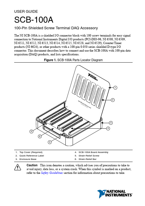
USER GUIDESCB-100A100-Pin Shielded Screw Terminal DAQ AccessoryThe NI SCB-100A is a shielded I/O connector block with 100 screw terminals for easy signal connection to National Instruments Digital I/O products (PCI-DIO-96, NI 6508, NI 6509,NI 6511, NI 6512, NI 6513, NI 6514, NI 6515, NI 6528, and NI 6529), Counter/Timer products (NI 6624), or other products with a 100-pin 0.050 series shielded D-type I/Oconnector. This document describes how to connect and use the SCB-100A with 100-pin data acquisition (DAQ) products, and lists specifications.Figure 1. SCB-100A Parts Locator Diagram1.Top Cover (Required)2.Quick Reference Label3.Enclosure Base4.SCB-100A Board Assembly5.Strain-Relief Screw6.Strain-Relief BarCaution This icon denotes a caution, which advises you of precautions to take toavoid injury, data loss, or a system crash. When this symbol is marked on a product,refer to the Safety Guidelines section for information about precautions to take.Safety GuidelinesThe following cautions contain important safety information concerning hazardous voltages and connector blocks.Caution Do not connect hazardous voltages (>30 V RMS/42 V peak/60 V DC).Refer to your product documentation for information about the electrical limits ofyour device or module.Caution Install cover prior to use. To avoid electrical shock, do not removeSCB-100A covers unless you are qualified to do so. Before removing the cover,disconnect any live circuit from the connector block. Replace cover for use.Caution The chassis ground lug on your SCB-100A is for groundinghigh-impedance sources, such as a floating source (1 mA maximum) and forterminating the shields of connected cables. Do not use the chassis ground lug as asafety earth ground.Electromagnetic Compatibility GuidelinesThis product was tested and complies with the regulatory requirements and limits for electromagnetic compatibility (EMC) as stated in the product specifications. These requirements and limits are designed to provide reasonable protection against harmful interference when the product is operated in its intended operational electromagnetic environment.This product is intended for use in residential, commercial, and industrial locations. However, harmful interference may occur in some installations or when the product is connected to a peripheral device or a test object. To minimize interference with radio and television reception and prevent unacceptable performance degradation, install and use this product in strict accordance with the instructions in the product documentation.Furthermore, any changes or modifications to the product not expressly approved by National Instruments could void your authority to operate it under your local regulatory rules.Caution To ensure the specified EMC performance, operate this product only withshielded cables and accessories.Caution To ensure the specified EMC performance, signal wires routed outside ofthe enclosure must be contained within a shielded cable and connected to shieldedaccessories. Cable shields must be terminated to the chassis ground lug using asshort a connection as is practical.2| | SCB-100A User GuideWhat Y ou Need to Get StartedTo set up and use your SCB-100A, you need the items shown in the following figure. You can find quick reference labels, which specify accessory pinout information for many compatible products, by going to /info and entering the Info Code scb100alabels .Figure 2.SCB-100A Installation Supply List1.SCB-100A 100-pin Shielded Connector Block Kit2.100-pin DAQ Device/Module and Documentation3.(Optional) Quick Reference Label PDF4.SH100-100-F Cable (Part Number 185095-0x)5.#2 Phillips Screwdriver6.0.125 in. Flathead Screwdriver7.16 AWG to 30 AWG Signal Wire8.Wire Cutters9.Wire Insulation StripperGetting Started with the SCB-100AThe following figure shows the SCB-100A printed circuit board (PCB) parts locator diagram.If the kit is missing any of the components in the figure, contact NI.SCB-100A User Guide | © National Instruments | 3Figure 3. SCB-100A PCB Diagram1.Screw Terminals2.100-Pin I/O Connector3.PCB Mount Screw4.Chassis Ground Lug and PCB Mount ScrewCaution The chassis ground lug on your SCB-100A is for groundinghigh-impedance sources, such as a floating source (1 mA maximum) and forterminating the shields of connected cables. Do not use the chassis ground lug as a safety earth ground.To get started with the SCB-100A, complete the following steps while referring to theprevious figures. If you have not already installed your DAQ device or module, refer to the4 | | SCB-100A User Guidegetting started guide that came with your product for instructions. Remove all cables from the SCB-100A before getting started.1.(Optional) Mount the SCB-100A to a panel or DIN rail, as described in the Mounting theSCB-100A section.2.Remove the cover.3.Remove the film from both sides of the cover.4.(Optional) Attach the quick reference label to the inside of the cover. For quick referencelabels for most compatible products, go to /info and enter the Info Codescb100alabels.Tip You can stand the cover in the SCB-100A for easy reference.5.Loosen the strain-relief bar by removing the strain-relief screws with a #2 Phillipsscrewdriver.6.Connect the wires to the screw terminals by stripping off the wire insulation, inserting thewires into the screw terminals, and securely tightening the screws with the flatheadscrewdriver. Refer to the Specifications section for screw-terminal wiring gauge andtorque information.Caution To ensure the specified EMC performance, signal wires routedoutside of the enclosure must be contained within a shielded cable andconnected to shielded accessories. Cable shields must be terminated to thechassis ground lug using as short a connection as is practical.7.Reinstall the strain-relief (if removed) and tighten the strain-relief screws. If the shieldedcable is too large to route through the strain-relief hardware, either use multiple,smaller-diameter cables or remove the top strain-relief bar and add insulation or padding if necessary to constrain the cable.8.Replace the cover.Caution You must install cover prior to use.Caution Do not connect input voltages >30 V RMS/42 V peak/60 V DC tothe SCB-100A. Input voltages >30 V RMS/42 V peak/60 V DC can damage theSCB-100A, all devices or modules connected to it, and the host computer.9.Connect the SCB-100A to the DAQ device or module using the SH100-100-F cable.Refer to the Specifications section for information about the SCB-100A I/O connector.Note To ensure the specified EMC performance, operate this product onlywith shielded cables.unch Measurement & Automation Explorer (MAX). In the left panel, expand Devicesand Interfaces to confirm that your DAQ device or module is recognized, and thenconfigure your device settings.SCB-100A User Guide| © National Instruments| 511.(Optional) Configure the DAQ device or module connected to the SCB-100A bycompleting the following steps.a.In MAX, right-click your DAQ device or module and select Configure.b.Configure the device or module properties and click OK.12.Test specific device functionality. Run a Test Panel in MAX by right-clicking your DAQdevice or module and selecting Test Panels. Click Start to test the device or modulefunctions.Note When you have finished using the SCB-100A, power off any external signalsconnected to the SCB-100A before you power off your computer.Mounting the SCB-100AYou can use the SCB-100A on a desktop, or mount it to a panel or a standard DIN rail. For two-dimensional drawings and three-dimensional models of the SCB-100A, visit / dimensions and search by product name.Panel MountingThree keyholes are located on the back of the SCB-100A for mounting it to a panel or wall. To mount the SCB-100A to a board or panel, complete the following steps.1.Download and print the panel mounting template PDF by going to /info andentering the Info Code scb100amounting.ing the template, mark the three points on the panel. Verify that the narrow ends of thepanel mounting screw keyholes are pointing up.3.Screw #6-32 panhead machine screws or M3 panhead machine screws into the pointsmarked on the panel, leaving room to easily remove the SCB-100A from the panel.Installed screw height for both screw types (from the wall to the top of the screw) is5 mm (0.2 in.).DIN Rail MountingThe NI 9913 DIN rail mounting kit (part number 781740-01) contains one clip for mounting the SCB-100A on a standard 35 mm DIN rail. Fasten the DIN rail clip to the accessory using two FLH #6-32 x 5/16" screws (included in the kit) with a #2 Phillips screwdriver, as shown in the following figure.Note The threaded holes on the SCB-100A for DIN rail mounting should not beused more than five times. Unscrewing and reinstalling the DIN rail clip willproduce a compromised connection between the DIN rail clip and accessory.6| | SCB-100A User GuideFigure 4. SCB-100A DIN Rail Clip InstallationClip the chassis onto the DIN rail with the larger lip of the DIN rail clip positioned up, as shown in the following figure.Figure 5. DIN Rail Clip Parts Locator Diagram1.DIN Rail Clip2.DIN Rail Spring3.DIN RailSecuring the Cover on the SCB-100AIn most cases, attaching the cover with the integrated magnets is sufficient. To permanently secure the cover to the SCB-100A base, you will need two M3 × 6 (#4-40 × 5/16")thread-forming Phillips panhead screws, such as Taptite® Trilobular® screws. You can purchase Taptite screws from many vendors.SCB-100A User Guide| © National Instruments| 7Complete the following steps.ing a 3.5 mm (9/64 in.) diameter drill bit, drill two holes through the silkscreenedcrosshairs on the label side of the cover. When drilling, place the cover on a flat surface, such as a drill press, and drill slowly to minimize burrs.2.Replace the cover on the base, lining up the drill holes with the holes in the enclosure.3.Screw the M3 × 6 (#4-40 × 5/16") screws in with a torque of 0.90 N · M to 1.13 N · M(8 in. · lb to 10 in. · lb). Screwing within the recommended torque range avoids strippingthe threads of the enclosure holes.Removing the SCB-100A PCB from the Base Complete the following steps to remove the SCB-100A from the base.1.Disconnect the cable from the SCB-100A, if connected, and remove the top cover.2.Loosen the strain-relief screws, shown in Figure 1, with a #2 Phillips screwdriver.3.Remove any signal wires from screw terminals with a flathead screwdriver.4.Remove the printed circuit board mount screws and chassis ground lug, shown inFigure 2, with a #1 Phillips screwdriver.5.Remove the connector screws, shown in the following figure, with a flathead screwdriver.6.Tilt the PCB up and pull it out of the enclosure base.Figure 6. SCB-100A Back View1.Connector Screws2.100-Pin I/O ConnectorNote The threaded holes on the SCB-100A for the PCB mounting should not beused more than five times. Unscrewing and reinstalling the PCB will produce acompromised connection.SpecificationsThe following specifications are typical at 25 °C, unless otherwise noted.Caution Do not connect hazardous voltages (>30 V RMS/42 V peak/60 V DC) tothe SCB-100A.8| | SCB-100A User GuidePower RequirementsMaximum current at screw terminalsTerminals 1-48, 51-980.5 ATerminals 49-50, 99-100 1 ACaution Maximum current allowed at screw terminals may be less than specifieddepending on the DAQ device or module connected to the SCB-100A. Refer to thedevice specifications for maximum ratings of your device or module. Physical CharacteristicsDimensions (including feet)14.7 cm × 14.7 cm × 3.0 cm(5.8 in. x 5.8 in. × 1.2 in.)Weight670 g (1 lb 7.6 oz)I/O connector One 100-pin male 0.050 series shielded D-typeconnectorNumber of screw terminals100, all I/O signals are available at screwterminalsScrew-terminal wiringGauge0.25 mm2 to 1.29 mm2 (30 AWG to 16 AWG)solid or stranded wireWire strip length 6 mm (0.24 in.)Temperature rating90 °C minimumTorque0.5 N · m to 0.6 N · m(4.4 in. · lb to 5.3 in. · lb)Wires per screw terminal One wire per screw terminalNote It may not be possible to connect wires to all screw terminals through theopening of the enclosure when using wire larger than 1.02 mm2 (18 AWG). Safety VoltagesMaximum voltage30 V RMS, 42 V peak, 60 V DCCaution Not for use for measurements of MAINS circuits or MeasurementCategories II, III, or IV.EnvironmentalOperating temperature0 °C to 70 °CStorage temperature-18 °C to 82 °CSCB-100A User Guide| © National Instruments| 9Operating humidity5% to 90% RH, noncondensingStorage humidity5% to 90% RH, noncondensingPollution Degree2Maximum altitude2,000 mIndoor use only.SafetyThis product is designed to meet the requirements of the following standards of safety for electrical equipment for measurement, control, and laboratory use:•IEC 61010-1, EN 61010-1•UL 61010-1•CAN/CSA-C22.2 No. 61010-1Note For UL and other safety certifications, refer to the product label, or visit/certification, search by model number or product line, and clickthe appropriate link in the Certification column.Electromagnetic CompatibilityThis product meets the requirements of the following EMC standards for electrical equipment for measurement, control, and laboratory use:•EN 61326-1 (IEC 61326-1): Class A emissions; Basic immunity•EN 55011 (CISPR 11): Group 1, Class A emissions•EN 55022 (CISPR 22): Class A emissions•EN 55024 (CISPR 24): Immunity•AS/NZS CISPR 11: Group 1, Class A emissions•AS/NZS CISPR 22: Class A emissions•FCC 47 CFR Part 15B: Class A emissions•ICES-001: Class A emissionsNote In the United States (per FCC 47 CFR), Class A equipment is intended foruse in commercial, light-industrial, and heavy-industrial locations. In Europe,Canada, Australia and New Zealand (per CISPR 11) Class A equipment is intendedfor use only in heavy-industrial locations.Note Group 1 equipment (per CISPR 11) is any industrial, scientific, or medicalequipment that does not intentionally generate radio frequency energy for thetreatment of material or inspection/analysis purposes.Note For EMC declarations and certifications, and additional information, refer tothe Online Product Certification section.10| | SCB-100A User GuideCE ComplianceThis product meets the essential requirements of applicable European Directives, as follows:•2014/35/EU; Low-V oltage Directive (safety)•2014/30/EU; Electromagnetic Compatibility Directive (EMC)Online Product CertificationRefer to the product Declaration of Conformity (DoC) for additional regulatory compliance information. To obtain product certifications and the DoC for this product, visit / certification, search by model number or product line, and click the appropriate link in the Certification column.Environmental ManagementNI is committed to designing and manufacturing products in an environmentally responsible manner. NI recognizes that eliminating certain hazardous substances from our products is beneficial to the environment and to NI customers.For additional environmental information, refer to the Minimize Our Environmental Impact web page at /environment. This page contains the environmental regulations and directives with which NI complies, as well as other environmental information not included in this document.Waste Electrical and Electronic Equipment (WEEE)EU Customers At the end of the product life cycle, all NI products must bedisposed of according to local laws and regulations. For more information abouthow to recycle NI products in your region, visit /environment/weee.电子信息产品污染控制管理办法(中国RoHS)中国客户National Instruments符合中国电子信息产品中限制使用某些有害物质指令(RoHS)。
EMC Teseq NSG 3040A多功能干扰源说明书
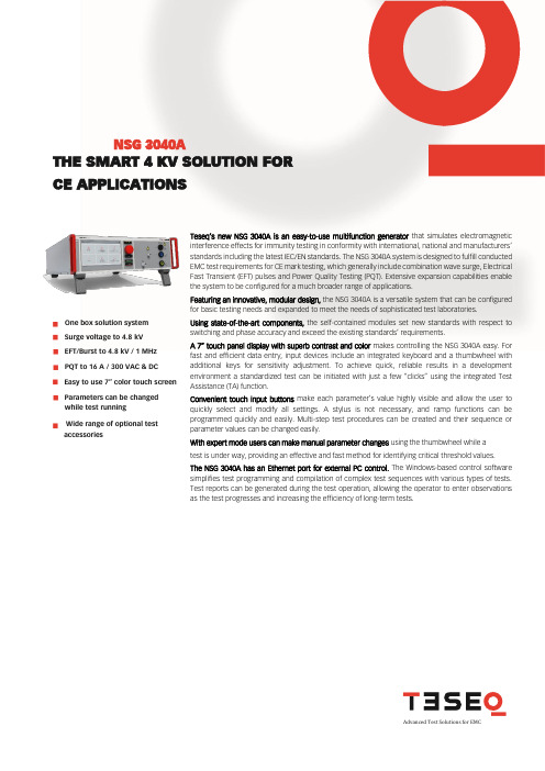
Teseq’s new NSG 3040A is an easy-to-use multifunction generator that simulates electromagnetic interference effects for immunity testing in conformity with international, national and manufacturers’ standards including the latest IEC/EN standards. The NSG 3040A system is designed to fulfill conducted EMC test requirements for CE mark testing, which generally include combination wave surge, Electrical Fast Transient (EFT) pulses and Power Quality Testing (PQT). Extensive expansion capabilities enable the system to be configured for a much broader range of applications.Featuring an innovative, modular design, the NSG 3040A is a versatile system that can be configured for basic testing needs and expanded to meet the needs of sophisticated test laboratories.Using state-of-the-art components, the self-contained modules set new standards with respect to switching and phase accuracy and exceed the existing standards’ requirements.A 7” touch panel display with superb contrast and color makes controlling the NSG 3040A easy. For fast and efficient data entry, input devices include an integrated keyboard and a thumbwheel with additional keys for sensitivity adjustment. To achieve quick, reliable results in a development environment a standardized test can be initiated with just a few “clicks” using the integrated Test Assistance (TA) function.Convenient touch input buttons make each parameter’s value highly visible and allow the user to quickly select and modify all settings. A stylus is not necessary, and ramp functions can be programmed quickly and easily. Multi-step test procedures can be created and their sequence or parameter values can be changed easily.With expert mode users can make manual parameter changes using the thumbwheel while a test is under way, providing an effective and fast method for identifying critical threshold values. The NSG 3040A has an Ethernet port for external PC control. The Windows-based control software simplifies test programming and compilation of complex test sequences with various types of tests. Test reports can be generated during the test operation, allowing the operator to enter observations as the test progresses and increasing the efficiency of long-term tests.One box solution system Surge voltage to 4.8 kV EFT/Burst to 4.8 kV / 1 MHz PQT to 16 A / 300 VAC & DC Easy to use 7“ color touch screen Parameters can be changed while test running Wide range of optional testaccessoriesTHE SMART 4 KV SOLUTION FOR CE APPLICATIONSNSG 3040ANSG 3040ATHE SMART 4 KV SOLUTION FOR CE APPLICATIONSThe NSG 3040A performs tests according to the following specifications:Combination wave pulse 1, 2/50 - 8/20 µs (Hybrid-Surge pulse)Pulse conforms to IEC/EN 61000-4-5Parameter ValuePulse voltage (open circuit): ±200 V to 4.8 kV (in 1 V steps)Pulse current (short circuit): ±100 A to 2.4 kAImpedance: 2/12 ΩPolarity: positive / negative / alternatePulse repetition: 10 s, up to 9’999 s (in 1 s steps)Test duration: 1 to 99’999 pulses, continuousPhase synchronization: asynchronous, synchronous 0 to 359º (in 1º steps)Coupling: IEC / externalBurst (EFT) 5/50 nsPulse conforms to IEC/EN 61000-4-4Parameter ValuePulse amplitude: ±200 V to 4.8 kV (in 1 V steps) - open circuit±100 V to 2.4 kV (50 Ω matching system)Burst frequency: 100 Hz to 1000 kHzPolarity: positive / negative / alternateRepetition time: 10 ms to 9'999 msBurst duration: 0.01 ms to 9'999 ms, single pulseTest duration: 1 s to 9’999s, 1 min to 1600 min, endlessPhase synchronization: asynchronous, synchronous 0 to 359º (in 1º steps)Coupling: internal / externalNSG 3040ATHE SMART 4 KV SOLUTION FOR CE APPLICATIONSDips & Interruptsconforms to IEC/EN 61000-4-11, IEC/EN 61000-4-29Parameter ValueDips & Interrupts: From EUT voltage input to 0 V, 0% (1)Uvar with optional variac: depending on model (VAR 3005A)Uvar with step transformer: 0, 40, 70, 80% (INA 650xA)Peak inrush current capability: > 500 A (at 230 V)Switching times: 1 to 5 μs (100 Ω load)Event time (T-Event): 20 µs to 9999 s, 0.5 to 9’999 cyclesRepetition time:10 ms to 9’999 ms, 1 to 9’999 sTest duration: 1 to 99’999 events, endlessPhase synchronization: asynchronous, synchronous 0 to 359º (in 1º steps)chapt. 5.1 a test voltage level from 0% to 20% of the rated voltage is considered as a total interruption.Variation test (with VAR 3005A only)conforms to IEC/EN 61000-4-11Parameter ValueUvar with optional variac: up to approx. 265 V (in 1 V steps) or up to 115% Uin (in 1% steps)Decreasing time Td: 1 ms to 9.999 s, 0.5 to 9999 cycles, abruptTime at reduced voltage Ts: 1 ms to 9.999 s, 0.5 to 9999 cycles,Increasing time Ti: 1 ms to 9.999 s, 0.5 to 9999 cycles,Repetition time: 1 s to 9’999 sEvents: 1 to 99’999Pulsed magnetic field in conjunction with MFC 30conforms to IEC/EN 61000-4-9Parameter ValueField: 100 to 1200 A/mPolarity: positive / negative / alternateRepetition time: 10 s to 9999s (in 1 s steps)Impedance: 2 ΩCoil / impedance factor: 0.01 to 100.00Test duration: 1 to 9’999 pulses, endlessPhase synchronization: asynchronous, synchronous 0 to 359º (in 1º steps)NSG 3040ATHE SMART 4 KV SOLUTION FOR CE APPLICATIONSPower magnetic field in conjunction with MFT 30 or MFO 6501 and MFC 30 & MFC 300conforms to IEC/EN 61000-4-8Parameter ValueField: 1 to max. 40 A/mFrequency: 50 or 60 HzCoil factor: 0.01 to 100Test duration: 1 s to 99’999 s, endlessInternal coupling networkParameter ValueEUT supply: 1-phaseEUT VAC: Up to 300 Vrms *, 50 / 60 Hz (phase - neutral)EUT VDC: Up to 300 VDCEUT current 1 x 16 Arms continuous (over heat protected)Connections: Front panel:Rear panel - EUT: 4mm banana plug- Burst OUT 50 SHV- Trigger out BNC- EUT supply: banana plug 4 mm- Additional ground connector- Instrument supply 85 V to 264 VAC - Connector surge HV – COMSurge Standard coupling as per IEC 61000-4-5Coupling mode Line to LineLine(s) to groundMains decoupling: 1.5 mH 0% + 35%Decoupling attenuation: Residual pulse voltage on EUT power supply inputs 15 % max.Residual voltage on non-pulsed EUT power supply inputs 15 % max. EFT (Burst) Standard coupling all lines to ref ground (GND)IEC / EN 61000-4-4L, N, PE to ref GNDAny lines and combinatio L tto ref GND: to ref GNDN to ref GNDPE to ref GNDL, N to ref GNDL, PE to ref GNDN, PE to ref GND PQT: Dips & interrupts to phase LNSG 3040ATHE SMART 4 KV SOLUTION FOR CE APPLICATIONSTechnical specificationInstrument supply 85 to 265 VAC, 50 / 60 HzDimensions NSG 3040A: 19”; 3 HU, 448 x 154 x 500 mm (W x H x D)Weight NSG 3040A: approx. 22 kg (49 lbs)Type DescriptionCDN 3043A-C32 Three phase automatic coupling decoupling network, 3x480 V / 32 ACDN 3425 Burst EFT capacitive coupling clamp for data line couplingCDN 117A-C4-4-1 Coupling networks for unsymmetrical signal-/data lines (surge)CDN 118A-C4-4-1 Coupling networks for symmetrical signal-/data lines (surge)CDN HSS-2 Coupling network for 2 kV surge pulse 1.2 / 50 μs IEC/EN 61000-4-5on unshielded symmetrical high speed telecom lines (Ethernet)PVF BKIT 1Burst/EFT verification setMD 210 Voltage differential probe 3.5 kV / 7 kVMD 300 Current probe 5 kAType DescriptionTVT 1-250-16Manual step transformer, 16 AAC, 0/40/70/80%VAR 3005A-S16 Automatic single variable transformer, 1 x 16 AAccessories for IEC/EN 61000-4-8/-4-9AMETEK CTSSternenhofstr. 15 4153 Reinach SwitzerlandT + 41 61 204 41 11 F + 41 61 204 41 00************************© December 2018 AMETEK CTSSpecifications subject to change without notice. Teseq® is an ISO-registered company. Its products are designed and manufactured under the strict quality and environmental requirements of the ISO 9001. This document has been carefully checked. However, Teseq® does not assume any liability for errors or inaccuracies.691-387 A December 2018Type DescriptionMFO 6501A Manual magnetic field option for -4-8MFC 30 Magnetic field coil 1 x 1 m, with MFO max. 40 A/m -4-8;Surge* max. 1200 A/m -4-9MFC 300 Magnetic field coil 1 x 1 m; max. 330 A/m -4-8。
R.STAHL 单通道安全屏障系列 9001 说明书

Single-Channel Safety BarriersSeries 900109965E00 R.STAHL safety barriers INTRINSPAK series 9001 are used for various applications in the arena of automation. Based on the broad range of versions and the possibility of various interconnections it offers for almost all tasks.The safety barriers enable the intrinsic safe operation of HART transmitter, proximity switches, potential-free contacts and temperature sensors, strain gauge, solenoid valves, indicators e.t.c. The compact design allows a space saving and flexible installation in the cabinet. The mounting is very comfortable and easy due to the fact that installation on the DIN-rail and the contact to the potential equalization is made in one step.ATEX / IECEX / NEC 505NEC 506GOST Class IZone012202122Zone012202122 Ex i interfaces x x x x x x Ex i interfacesInstallation in x x Installation in x xSingle-Channel Safety BarriersSeries 9001Explosion ProtectionGlobal (IECEx)Gas and dust IECEx PTB 09.0001XEx nA [ia Ga] IIC T4 Gc[Ex ia Da] IIICEurope (ATEX)Gas and dust PTB 01 ATEX 2088 XE II 3 (1) G Ex nA [ia Ga] IIC/IIB T4 GcE II (1) D [Ex ia Da] IIICUSA (NEC)Gas and dust3011002 (FM)CL. I, DIV.2, GP. A,B,C,D, T4 AND CL. I, ZONE 2, GP. IIC/IIB T4,INTRINSICALLY SAFE CONNECTIONS FORCL. I,II,III, DIV. 1, GP. A,B,C,D,E,F,G AND CL. I, ZONE 0, GP. IIC/IIBE81680 (UL)CLASS I, DIV. 2, GROUPS A,B,C,DCLASS II, DIV. 2, GROUPS F,GCLASS IIIRussia (GOST-R)Gas[Exia Ga] IIC/IIB/IIAExnA [iaGa] IIC/IIB/IIA T4 GcCertificates and approvalsCertificates IECEx, ATEX, Canada (CSA), Kazakhstan (GOST-K), Russia (GOST-R), Serbia (SRPS),Ukraine (GOST-U), USA (FM, UL), Belarus (GOST-B)Further parametersInstallation in Zone 2, Division 2 and in safe areaFurther information see respective certifcate and operating instructionsTechnical dataElectrical dataTransmissioncharacteristicLeakage current at U N( 2 m A (if not stated otherwise)Temperature effect( 0.25 % / 10 KTransmissionfrequencyAt resistive currentlimitationI m( 50 mA( 50 kHzI m) 50 mA( 100 kHz( 10 kHzAt electronic currentlimitationAmbient conditionsAmbient temperature-20 ... +60 °C / -4 ... +140 °FStorage temperature-20 ... +75 °C / -4 ... +167 °F95 % mean, no dewingMaximum relativehumidityMechanical dataIngress protectionaccording to IEC 60529terminal enclosure IP20Casing IP40Enclosure material Polyamide 6 GFConnection 4 cage terminals, each maximum 1.5 mm2 flexible / solid2 PA-terminals, each maximum 4 mm2 flexible / solidWeight approx. 0.115 kgA2A2A2A2A2A2A2A2A2A2A2A2A2A2Single-Channel Safety Barriers Series 9001Selection Table Version DescriptionType Page Single-channel barriers•Earthed electric circuit•Current limiting to < 100 mA9001/014•Earthed electric circuit•Connection to regulated power supply U N 9001/015•Application for floating contacts •Nominal current limited to < 40 mA •Earthed electric circuit•Connection to unregulated power supply U N between + 20 and 35 V DC 9001/017•Application for floating contacts •Nominal current limited to < 40 mA •Earthed field device•Connection to unregulated power supply U N between + 20 and 35 V DC9001/018•Application for solenoid valves, LEDs or audible signals •Earthed electric circuit•Connection to unregulated power supply U N between + 20 and 35 V DC 9001/019•Earthed electric circuit•Connection to regulated power supply U N9001/0010•Earthed electric circuit•Suitable for alternating current and direct current 9001/0211•Earthed electric circuit•Suitable for alternating current and direct current •Current limiting to < I max9001/0213•Earthed electric circuit•For the evaluation of direct current signals •Current limiting to < I max9001/0314•Application for HART transmitters •Earthed field device•Connection to unregulated power supply U N between + 20 and 35 V DC 9001/5115•Application for transmitters •Earthed field device•Connection to unregulated power supply U N between + 20 and 35 V DC9001/5117Single-Channel Safety Barriers for Positive Potential Series 9001/01Single-Channel Safety Barriers for Positive Potential Series 9001/01Single-Channel Safety Barriers for Positive Potential Series 9001/01Single-Channel Safety Barriers for Positive Potential Series 9001/01Single-Channel Safety Barriers for Positive Potential Series 9001/01Single-Channel Safety Barriers for Positive Potential Series 9001/01Single-Channel Safety Barriers for Negative Polarity Series 9001/00Single-Channel Safety Barriers for Alternating Polarity Series 9001/02Single-Channel Safety Barriers for Alternating Polarity Series 9001/02Single-Channel Safety Barriers for Alternating Polarity Series 9001/02Single-Channel Diode Return Barriers for Positive Polarity Series 9001/03Single-Channel Safety Barriers for Transmitters Series 9001/51Single-Channel Safety Barriers for Transmitters Series 9001/51Single-Channel Safety Barriers Series 900109919E0009920E0009921E0009922E0009924E0003856E0009926E0009926E0009927E0009928E00Single-Channel Safety Barriers Series 9001。
Omron K8AB-PA 三相偏差、相序、失相保护器说明书

c All Rights Reserved
9419061-9 C
Precautions for Safe Use
Make sure to follow the instructions below to ensure safety.
1. Do not use or keep this product in the following environments.
ʢ6ʣThe type K8AB-PA can only detect phase interrupt -ion when the interruption occurs on the side where power supply exists from the point of connection, and interruption on the loading side cannot be detected.
install switches or circuit breakers that conform to relevant requirements of IEC60947-1 and IEC60947-3, and label them appropriately. 11. For DC input, use a SELV power-supply capable of overcurrent protection. Specifically, a SELV powersupply has a double or reinforced insulation for input and output, and output voltage of 30Vr.m.s with 42.4V at peak or DC60V maximum. Recommended power-supply : Model S8VS-06024˘ (Omron product) 12. Do not turn a setting volume beyond the scope of movement.
减速机-标准

GB/Z 22559.2-2008 GB/Z 6413.1-2003
GB/Z 6413.2-2003
GB/T 10095.1-2008 GB/T 8542-1987 GB/T 8543-1987 GB/Z 18620.1-2008
GB/Z 18620.2-2008
GB/Z 18620.3-2008
JB/T 8831-2001 JB/T 8853-2001 JB/T 9050.3-1999 JB/T 9051-1999 JB/T 10419-2005
JB/T 10420-2004 JB/T 10421-2004 JB/T 9173-1999 JB/T 10422-2004
JB/T 10423-2004
ANSI/AGMA 6025-D-1998 ANSI/AGMA 6032-A-1994 ANSI/AGMA 6033-2008 ANSI/AGMA 6034-B-1992
ANSI/AGMA 6035-2002
ANSI/AGMA 6101-E-2008ANSBiblioteka /AGMA 6114-A-2006
ANSI/AGMA 6123-B-2006 ANSI/AGMA 6133-2008 ANSI/AGMA 6135-2008 ANSI/AGMA ISO17485-A-2008 ANSI/AGMA ISO18653-2006 ANSI/AGMA ISO23509-A-2008 GB/T 3374.1-2010
SWL 蜗轮螺杆升降机 型式、参数与尺寸
高速渐开线圆柱齿轮和类似要求齿轮承载能力计 算方法
工业闭式齿轮的润滑油选用方法
圆柱齿轮减速器
圆柱齿轮减速器加载试验方法
平面包络环面蜗杆减速器
摆线针轮行星传动 摆线齿轮和针轮 精度
- 1、下载文档前请自行甄别文档内容的完整性,平台不提供额外的编辑、内容补充、找答案等附加服务。
- 2、"仅部分预览"的文档,不可在线预览部分如存在完整性等问题,可反馈申请退款(可完整预览的文档不适用该条件!)。
- 3、如文档侵犯您的权益,请联系客服反馈,我们会尽快为您处理(人工客服工作时间:9:00-18:30)。
ANSI/AGMA 1106-A97ANSI/AGMA 1006-A97米制单位版美国国家标准塑料齿轮齿形尺寸AGMA标准美国国家标准塑料齿轮齿形尺寸ANSI/AGMA 1106-A97(ANSI/AGMA 1006-A97 米制单位版)美国国家标准的批准,需要由美国全国标准学会审核,查明标准编制部门业已达到应履行的程序、一致同意和其他审批准则的要求。
当根据美国全国标准学会标准评审委员会的裁决,涉及直接利害和物质利害关系方业已达成相当多数同意时,一致同意即告成立。
相当多数同意表示比简单多数要多得多,但不一定无异议。
一致同意要求一切观点和异议均加以考虑,并协同努力达成彼此的消解。
美国国家标准的采用纯属志愿性的;不拘是否赞同该标准,国家标准的实行毫不妨碍任何人不遵照它开展制造、营销、采购,或运用产品、方法或程序等活动。
美国全国标准学会不制订标准,也决不对任何美国国家标准作解释。
此外,无人有权或被授权以美国全国标准学会的名义,发表对美国国家标准的解释。
有关对本标准解释的要求,应该发送给美国齿轮制造商协会。
指示:AGMA(美国齿轮制造商协会)技术出版物依发展经历而定,持续进行改进、修订或撤销。
一切参阅任何AGMA技术出版物的人员,应该查明该出版物应是能从该协会取得的该论题最新版本。
[可以引用或摘录表格或其他内容独立的段落。
应注明文献出处,格式如下:承出版者美国齿轮制造商协会(the American Gear Manufacturers Association,1500 King Street ,Suite 201,Alexandria,Virginia 22314)许可,摘录自ANSI/AGMA 1106-A97“塑料齿轮齿形尺寸”(Tooth Proportions for Plastic Gears)]批准日期1997年8月7日摘要本标准介绍一种新版基本齿条AGMA PT,此新版基本齿条采取全圆型齿根圆角,可以在塑料制齿轮的许多应用场合优先选用。
本标准还解释和阐明基本齿条一般概念。
标准中包括如何从设计齿厚和基本齿条数据推算出直齿或斜齿齿轮尺寸的说明,并附有公式和示范计算。
公式和计算采用ISO规定的符号和米制单位。
编有几个附则,叙述本基本齿条可能的修正方案,还介绍一种不用基本齿条概念确定齿形尺寸的方法。
出版者美国齿轮制造商协会版权Copyright©1997 by American Gear Manufactuer&Association 版权所有。
未经出版者书面许可,不得以任何方式复制,或存储于电子检索系统等。
美国印制ISBN:1-55589-685-5目录前言1内容范围2定义和符号3齿形尺寸和基本齿条4塑料齿轮标准基本齿条5得自基本齿条数据的齿轮齿形尺寸表1术语:符号和名称2标准基本齿条(单位模数基准)图1AGMA PT基本齿条(m或m n=1)2齿端修薄的AGMA PT基本齿条实例3根据AGMA细齿距标准和根据AGMA PT基本齿条标准计算的齿根圆角弯曲应力比较4(a)齿根圆角角形对模内流动的影响4(b)齿根圆角角形对表面近处(端面宽中间部位)纤维排列方位的影响5外齿轮齿顶圆角倒圆引入的齿廓参数附则A基本齿条说明和应用B塑料齿轮试验性基本齿条C齿厚和其他设计变量的确定D得自修正基本齿条的齿轮、齿端、修薄E齿廓尺寸的另类确定方法F齿轮几何尺寸非齿条法生成G计算示例参考资料前言(如果有前言、脚注和附则,也仅是为了提供资讯而编入,不应视为ANSI/ AGMA1106-A97塑料齿轮齿形尺寸标准的一部分)美国齿轮制造商协会(AGMA)多年来发布了一系列有关齿轮齿形尺寸的标准。
最近的标准有:AGMA201.02(1995年撤销)“粗齿距渐开线直齿齿轮齿形尺寸”和ANSI/AGMA1003-G93“细齿距渐开线直齿和斜齿齿轮齿形尺寸”)这两个标准和它们原先的版本是为了回应齿轮成形切削刀具如滚刀和插齿刀的标准化需要而编制的。
如无这类标准,齿轮车间所需刀具的类型便会变得无数多了。
采取模塑方法制造齿轮,所受到的实际限制与采用齿轮切削方法来制造有所不同。
每个模具都具有固有的“非标准”属性。
模腔(阴模)由于收缩允许误差是变动的,其几何尺寸不可能遵循一个标准。
再者,有几种制造阴模的方法与切削刀具无关,即便二者有关联,一般也需要采用专用刀具。
因此,模塑塑料齿轮齿形尺寸无需遵循适用机加工成形齿轮的惯用规范。
塑料材料某些特有性能会影响齿轮齿形尺寸的选取,如下述二例所示:·塑料分子的结构和排列定向,不管是什么加工方法,都会造成材料强度对尖锐内角特别敏感。
如果齿根能避免圆角,则轮齿便能具备相当高的强度。
按照上述AGMA细齿距标准制造的齿轮,其齿形尺寸通常会造成较尖的齿根圆角。
·在某些应用场合,由于塑料的膨胀性较强,使得配对齿轮间的啮合高度需要比其它标准齿形所许可的值要大。
有鉴于采用另外的齿形更为合适,塑料齿轮模塑行业成员便采纳了几个他们自行制订的齿形尺寸制式。
Willianm Mckingley(威廉•麦金利)曾提出一个制式[1],这个制式已获得塑料齿轮设计界广泛采用,并且常代替AGMA细齿距标准作为规定要求。
因为这些齿形尺寸包含有模塑齿轮优先选用的尺寸,并且因为已经为产业界所公认,经过作某些变更后,曾在编制本标准过程中用作范本。
这个制式含有4个型号,其中第一个型号中的啮合高度,也即工作高度与上述几个AGMA标准相同。
其它3个型号的啮合高度有所增大,但增大程度有所不同。
第一个型号的应用最为广泛,所以本标准仅选用它作为新齿形尺寸的范本。
但是,本标准仍在附则B中编入了相仿的基于其它3个型号的数据。
本标准中齿形是采用基本齿条概念来确定的。
为供不熟悉基本齿条概念的使用者参考,特设附则A编入关于基本齿条的详介。
欢迎对本标准提出改进意见。
请径寄美国齿轮制造商协会(the American Gear Manufacturers Association,1500 King Street ,Suite 201,Alexandria,Virginia,22314,USA)美国国家标准——塑料齿轮齿形尺寸1.范围1.1基本齿条本标准规定直齿和斜齿塑料齿轮基本齿条。
但是,一切类型的齿轮,凡使用基本齿条概念作为辅助工具来确定其几何尺寸的,特定的基本齿条也同样适用。
注:本基本齿条与其它几种AGMA基本齿条可从中任选使用。
在轮齿弯曲强度是塑料齿轮设计中的主要因素的应用场合,常优先选用本基本齿条。
在附则A中编入有关基本齿条基本概念的详细说明,包括其各项参数及其在各种类型齿轮中的应用。
在附则B中列出主要是啮合高度有所不同的其它三种基本齿条的数据。
1.2齿轮齿形尺寸本标准阐明一旦齿厚确定后,基本齿条的尺寸是如何来决定齿轮齿形尺寸的。
本标准不涵盖齿轮齿厚具体数值以及最终的齿轮齿形尺寸。
但是,在附则C中讨论了选择这些参数时所应考虑的众多因数。
附则D讨论由修正基本齿条来修薄齿轮齿端的步骤。
1.3齿形尺寸的非传统确定方法附则E和F介绍当前用于协助完成对其应用要求最优的齿轮设计某些非传统方法。
现代的阴模制造方法使得模塑齿轮的应用变得更为方便。
这些方法的内容包括修正标准基本齿条,生成按定制要求设计的基本齿条,和不采用基本齿条来设计齿形尺寸。
在此二附则中,每种方法的介绍还包括可能的优点和设计注意事项等内容。
附则F并介绍了新近的,即设计不用基本齿条方法的一个步骤的实例。
2.定义和符号2.1定义本标准所用名称遵循ANSI/AGMA1012-F90“齿轮术语、名称定义和符号”及AGMA904-B89“米制单位用法”的规定。
本标准用到的名称凡属于需要加以推敲的,和概念属于塑料齿轮所专用的,可在它们初次出现的地方查得。
2.2符号表和公式中应用研究的符号列于表1。
注:本标准所采用的符号和定义可能与其它AGMA标准中类似项目有所不同。
使用者对熟悉的符号不可认为无需认真查阅其定义就可以使用。
表I术语:符号和名称3、轮齿尺寸和基本齿条通行的作法是规定一个基本齿条来建立轮齿尺寸体系。
通常即由此齿条形齿廓的造形作用,决定具有规定齿数和齿厚值齿轮的真实齿廓。
(齿廓有些参数可由另外一些因素来确定,见5.8.1、5.8.2和5.8.3条款)有关此基本齿条概念以及如何将其运用于各类齿轮的叙述见附则A。
4、塑料齿轮标准基本齿条本AGMA标准规定了标准的基本齿条。
齿形遵循本基本齿条规定的塑料齿轮,兼与AGMA细齿距齿轮及ISO粗齿距齿轮二者啮合良好。
(附则B规定了三种较大工作齿高的试验性基本齿条)注:本基本齿条可以与其它几种AGMA基本齿条互替选用。
在塑料齿轮设计中弯曲强度是主要因素的这类场合,优先选用本齿条。
见4.4条款。
4.1标注本基本齿条标注如下:AGMA塑料齿轮装置齿形(Plastic Gearing Toothform),简写为AGMA PT.4.2尺寸基本齿条示于图1。
图中注出了附则A.3所叙述的全部参数。
这些尺寸参数的值列于表2,同时并列出AGMA细齿距标准和ISO粗齿距(多半为粗齿距)标准的规定值,以资对比。
所有这些数值全部以单位模数为基准。
将表中数值乘以模数,即求得实际值。
图1 AGMA PT基本齿条(m或m n=1)尺寸参数c BR —顶隙h fBR —形状齿根高r fBR —齿根圆角半径e BR —齿槽宽h kBR —工作齿高s BR —齿厚h aBR —齿顶高h tBR —全齿高α —齿形角h fBR —齿根高P BR —圆周齿距表2标准基本齿条(单位模数基准)4.3选用性修形这些基本齿条可以进行一定的修形,而其基本特性保持不变。
是凡需要作这类修改时,在齿轮规格说明书内须包括一份适当的说明。
4.3.1齿廓修形有时对齿轮渐开线齿廓稍作修形是可取的。
这类情况的一个实例是齿顶修薄。
这是沿着连接齿顶的这段渐开线,切除一层细薄片材料。
齿顶修薄因能缓解伴随毗连齿轮之间传递载荷所发生的迅猛作有(尤其当齿轮经受重载荷而发生弯曲时),而常有益于齿轮的工作,实施齿廓这种修形的方法是对基本齿条直线形齿侧进行适当的修形。
当采用这一方法时,需要提供修形的基本齿条图纸作为齿轮规格说明书的一部分。
图2所示为适用AGMA PT齿形的这种修形实例。
附则D列出了用于计算本类修形对切成齿形某些参数的影响的公式。
图2 AGMA PT基本齿条齿顶修薄的修形实例4.3.2齿顶直径修正有时候需要改变内齿轮的外直径或内齿轮的内直径,使之不同于基本齿条所确定的直径。
此类情况所要考虑的因素在5.8.1条款和附则C中讨论。
此类情况修正量较之标准基本齿条不大,无需绘制专门的基本齿条图样表示修正情况。
外直径或内直径大小注明本身,便足以说明修正的情况。