freeform lens design for led collimating illumination
玻璃产品创意拍摄方案
玻璃产品创意拍摄方案1. "Reflective Elegance" - Showcase the beauty and versatility of glass products through reflective shots. Capture the stunning interplay of light and glass surfaces to highlight their aesthetic appeal.2. "Vibrant Vessels" - Create a series of photos featuring glass vases filled with colorful flowers. Explore the contrast between the transparency of the glass and the vibrancy of the flowers to evoke a sense of natural beauty.3. "Frozen Motion" - Freeze glass products in mid-air to capture the sense of dynamic movement. Use high-speed photography techniques to capture the intricate details of glass shattering or liquid swirling inside glass objects.4. "Submerged Serenity" - Dive into an underwater setting to capture glass products gracefully floating in turquoise waters. Show how glass can interact with the natural environment, reflecting and refracting light to create a tranquil ambiance.5. "Enchanting Shadows" - Photograph glass pieces against different light sources to create captivating shadow patterns. Play with light angles and textures to capture unique and mesmerizing shadow effects on the surrounding surfaces.6. "Luminous Sculptures" - Illuminate glass sculptures from within to emphasize their intricate designs and textures. Experiment with different colored lights to create a magical and otherworldly feel.7. "Minimalist Sophistication" - Utilize a clean and minimalist setup to showcase the elegance and simplicity of glass products. Focus on the clean lines, transparency, and symmetry of the subject, allowing the beauty of the glass to speak for itself.8. "Industrial Fusion" - Combine glass products with industrial elements, such as metal or concrete, to create a juxtaposition between fragility and strength. Capture the contrast between the delicate nature of glass and the harshness of the industrial surroundings.9. "Playful Reflections" - Use mirrors or other reflective surfaces to create unique reflections of glass products. Experiment with angles and perspectives to capture distorted or abstract reflections, adding a touch of creativity to the images.10. "Whimsical Glass Gardens" - Arrange glass products in a lush and colorful garden setting to create a whimsical tableau. Incorporate elements such as butterflies, flowers, or other natural elements to evoke a sense of enchantment and wonder. (Note: The lack of explicit titles in the text is due to the nature of the request. However, each phrase can still serve as a descriptive guideline for the visual concept.)。
IRIDEX PASCAL LIO激光间接检眼镜操作手册说明书
PASCAL® 激光间接检眼镜 (LIO) (532 nm 或 577 nm)(单光点版本)操作手册European Authorized Representative Iridex Corporation Obelis 1212 Terra Bella Avenue Boulevard Général Wahis 53 Mountain View, CA 94043 1030 Brussels 美国比利时 办事处:+1.650.940.4700 电话:+32.2.732.59.54 传真:+1.650.962.0486传真:+32.2.732.60.03 本手册受版权保护,并保留所有权利。
根据版权法,未经 Iridex Corporation 明确书面许可,不得全部或部分复制本手册,亦不得以任何其他媒介转载。
允许使用的副本必须按法律规定载有与原件相同的所有权和版权声明。
复制包括翻译成另一种语言。
请注意,尽管我们已尽力确保本文档中提供的数据准确无误,但本文包含的信息、数字、插图、表格、规格和示意图如有更改,恕不另行通知。
Iridex Corporation®、Iridex Corporation Logo™ 和 PASCAL® 和 PASCAL Synthesis™ 为 Iridex Corporation 的商标或注册商标。
目录目录 (3)简介 (5)设置和使用 LIO (6)调整头带 (7)调整瞳孔间距离 (8)获取融合图像 (9)调整检镜角度 (9)打开照明 (9)设置光圈 (10)选择滤镜 (11)调整照明 (12)调整激光器角度 (12)适配电源 (13)激光治疗 (14)检查眼底 (14)电池充电器 (15)插入/更换电池组 (15)电池组充电 (16)安装无线充电器 (19)更换 LED (20)清洁 (21)规格 (21)产品标签 (22)保养维修 (22)一般安全和法规信息 (23)设备分类 (23)预期用途 (23)警告和注意事项 (23)安全考虑事项 (26)符号 (27)电磁兼容性 (28)担保信息 (37)发货、退货和调整担保 (37)退回设备去污 (38)美国技术服务信息 (38)WEEE 弃置 (38)去污证明 (39)简介请阅读并认真遵守这些说明。
LensDesign-光学设计教程

公认的光学设计宝典结合ZEMAX实例n Joseph M. Geary著n赵存华译特点:²以ZEMAX软件为实例²理论讲解与软件操作相结合²以讲座的形式写作全书²以照相镜头的发展历史贯穿全书²深入浅出有深度易理解²从初学到精通光学设计者皆宜该书是Joseph M. Geary即将退休之作,集其毕生科研实践之精华,Geary是美国Alabama大学著名的光学研究中心的教授,SPIE的Fellow,从事镜头设计四十余年,有着丰富的镜头设计经验,阅读该书就是您与大师对话,亲身聆听教诲的机会。
前言本书来自于Huntsville市Alabama大学应用光学研究中心光学工程专业博士生的学位课。
虽然有很多设计各种镜头方面的专著和论文集,但在教这门课开始的时候,令我十分沮丧和失望的是,我无法找到一本好的镜头设计方面的教材。
还没有人针对学生学习(或教师)思路来编写教材,因此希望本书在镜头设计教学方法上迈出一步。
它就像我最初打算的一样,现代镜头设计教材不可能完全脱离可利用的商业光学设计软件,因此考虑几个原因(如界面友好和高性价比等),作者选择了ZEMAX。
本书不是传统意义上的教科书,它是形式化地体现了我演讲的内容,包括作业和考试。
本教材设计为一学期课时,38讲,每讲55分钟。
所讲的知识为研究生一年级的水平,并尽力为镜头设计最初级教程而写,同时也可作为手册子或工程设计参考。
它基本的要求是:熟练掌握大学所学的几何光学(附录A)知识,数学上的代数、三角、几何和微积分等。
尽管本教材是为镜头设计者所写,但它所提供的光学工程的一般知识可作为一个重要的工具或技巧而应用于其它专业技术中。
虽然本书以演讲的格式而作,并以适合课堂使用为特点,但是其根本上是为自学者而设计。
充分考虑到使用者的三种不同情况。
显然其最大的受益者为能获得ZEMAX(及其随机手册)软件的读者;同时作者也提供(特别在附录C和E 的帮助下)了足够的知识允许读者使用其它光学设计软件(如Code-V,SYNOPSIS 或高级OSLO等)复算实例和做作业;最后对于无法使用流行光学设计软件的读者,可以大量学习或分析,通过公式手算或做薄透镜进入软件设计前的计算工作,有所裨益。
MARL 202系列灯泡替换型LED说明书

202SERIESBULB REPLACEMENT LED2015/863/EURoHS FEATURESBENEFITS•T1Midget Flange SX3s Base •Water clear lens •Flat topped LED•Centre contact Anode as standard •Range of LED colour options •Range of voltage options•Direct replacement for standard bulb fitting •Water clear lens gives clear “off”state•Flat topping gives even illumination of large lens areas •Direct replacement for standard polarity installations •No colour filter required•Manufactured with internal resistor •Outstanding reliability202-301-20-38Red 5-62033640-30to +85-40to +85202-325-20-38Yellow 5-620401590-30to +85-40to +85202-324-20-38Green 5-6201010525-30to +85-40to +85202-934-20-38Blue5-620225471-30to +85-40to +85202-991-20-38Warm White 5-620Call See Below -30to +85-40to +85202-998-20-38Cool White 5-6201194See Below -30to +85-40to +85202-301-21-38Red 122033640-30to +85-40to +85202-325-21-38Yellow 1220401590-30to +85-40to +85202-324-21-38Green 12201010525-30to +85-40to +85202-934-21-38Blue1220225471-30to +85-40to +85202-991-21-38Warm White 1220Call See Below -30to +85-40to +85202-998-21-38Cool White 12201194See Below -30to +85-40to +85202-301-23-38Red 24-281527640-30to +85-40to +85202-325-23-38Yellow 24-2815308590-30to +85-40to +85202-324-23-38Green 24-2815830525-30to +85-40to +85202-934-23-38Blue24-2815175471-30to +85-40to +85202-991-23-38Warm White 24-2815Call See Below -30to +85-40to +85202-998-23-38Cool White 24-2815932See Below -30to +85-40to +85202-301-24-38Red 481218640-30to +85-40to +85202-325-24-38Yellow 4812208590-30to +85-40to +85202-324-24-38Green 4812615525-30to +85-40to +85202-934-24-38Blue4812125471-30to +85-40to +85202-991-24-38Warm White 4812Call See Below -30to +85-40to +85202-998-24-38Cool White4812648See Below -30to +85-40to +85X 0.4330.4330.4400.440Y0.4030.4150.4230.411X 0.2960.2830.3300.330Y0.2760.3050.3600.318NOTESIntensities (lv)and colour shades of white (X-Y co-ordinates)may vary between LEDs within a batch.Additional LED Colours,Voltage Options and Reverse Polarity options available for semi-custom projects.Please contact our Sales Team.All LED components are supplied in anti-static packaging.*Characteristics at Ta =25°C.For operating temperature derating graphs,please refer to sheet 2.TECHNICAL DATATECHNICAL DRAWINGDE-RATING GRAPHSDESIGN CONSIDERATIONSSingle-Chip LEDsAll devices feature water clear high intensity LEDs as standard.In devices where discrete LEDs are used,the single chip LED devices have been modified by the removal of the domed portion of the encapsulation (flat-topped)to provide even illumination of switches and annunciators.Non flat topped versions are also available.Flat-topping does not apply to devices using surface-mounted device (SMD)LEDs.Product EvaluationFilament replacement LEDs have been specifically designed to meet the primary objective of providing improved reliability.As this product range is suitable for both new-build and retro-fit,(sometimes in very old systems),a wide range of illuminated push button switches and lamp holders can be encountered.Due to subjectivity,evaluation of the LED type is recommended,(samples of all standard models are available).Care should be taken to correctlysimulate operating ambient light conditions to ensure that the correct device has been selected to maximise viewing characteristics such as viewing angle,colour compatibility and on/off contrast ratio.Electro-Static Discharge (ESD)Build up of electro-static discharge occurs in many situations involving people moving and handling products.The range of possible situations is very diverse but voltage levels as high as several thousand volts can and do arise in many individual situations.When an operator charged up to these levels handles a static sensitive device,there is a very probable likelihood that the device will be irreversibly damaged.It is essential that precautions are taken at all stages during manufacture and assembly of these products.Although LEDs were never considered to be static sensitive devices,changes in manufacturing technology and materials used to produce higher intensity products over a large range of the wavelength spectrum have changed this.Marl has an approved system of ESD control from goods in,through production and into final packing and despatch.Marl recommend all users of LED based products follow the current BSI guidelines for protection of electronic devices from electrostatic phenomena.Voltage,Current and TemperatureThe forward voltage /current value of an LED is dependent upon the ambient temperature of the environment in which it is operated.Therefore,care must be taken to operate the LED at the correct voltage /current values,depending upon the ambient temperature.Marl should be contacted if the device is to be operated outside the temperature range specified.Marl accept no liability for any product that is operated outside the stated voltage or temperature range.Weight (g):0.3Dimensions in mm (typical).Not to scale.Green dot on base of product signifies centre contact cathode -ve.Colour sleeve on product denotes LED colour.Series Lamp Base StyleMetric Equivalent Max.Power Dissipation202T1Sub Midget Flange SX3s 3360mmmW。
Leica M820 F19 优质眼科手术显微镜 说明书
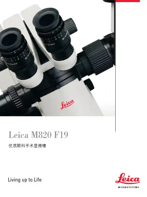
Leica徕卡产品,由Christophe Apothéloz设计徕卡与众不同明快、清晰!Leica APO OptiChrome TM M820光学系统呈现的高分辨率图像是您观察解剖细节最佳的解决方案。
患者安全,医生轻松!Leica独到的直接照明系统,在低照度安全照明下保证最佳的清晰度、对比度和色彩还原度。
双光束立体照明系统!独特的8-系列双光束照明系统保证医生获得稳定的红光反射和三维图像。
OttoFlex II OttoFlex II任何情况下都能实现完美的人机工效性 徕卡显微系统的全球运作分为四个部门,已进入各地市场领导者行列:• Life Science Division徕卡公司生命科学部门为科研用户提供最先进的显微成像技术,实现显微结构的观察、测量和分析。
理解并满足用户的科研应用是我们在市场中领先的关键。
• Industry Division徕卡公司工业部门的工作核心工作是支持客户寻求高质量的最终结果。
徕卡公司提供了最好、最新颖的成像系统,满足他们在日常工作以及在工业研究应用中的观察、测量和分析微观结构的需要,满足材料科学和质量控制、法医学科学调查和教育应用的需要。
• Biosystems Division徕卡公司病理系统部门为组织病理学实验室和研究人员带来了最全面的高质量病理产品系列。
从病人到病理学家,该范围包括每个组织学步骤所需要的理想的产品,还包括整个实验室所需要的高效工作流程解决方案。
借助以自动化革新和 Novocastra™ 试剂为特色的全套组织学系统,徕卡公司通过迅速、准确的诊断和密切的客户协作,更好地关心病人。
• Surgical Division徕卡公司手术显微镜部门的工作重点是与手术外科合作,以无论是现在还是将来都是最优秀、最新颖的手术显微技术为他们提供支持,照顾他们的病人。
“与用户合作,使用户受益”徕卡显微系统Ernst Leitz 于 1907 年发表了“与用户合作,使用户受益”的声明,描述了徕卡显微系统与最终用户的通力协作以及不断创新的驱动力。
手机LENS知识
LENS设计大全Lens作为手机的一个非常重要的部件,承载非常重要的任务:保护LCD ,透光良好,外观装饰作用等。
(一)Lens通用材料:1) PMMA:目前手机上的LENS都是用PMMA材料透光性好≥91%,表面硬度高,通过表面硬化处理(hard coating)后可达到3H 以上●注塑用的主要有:IH830(LG), VRL-40(三菱),MI-7(法国ATO)其中透光率IH830(93%)=MI-7(93%)>VRL-40(92%)表面硬度三种基本差不多。
抗冲击性能:VRL-40=MI-7>IH830价格:MI-7>VRL-40>IH830综合考虑:通常采用较多的是VRL-40。
●板材有:NR200(三菱)2)PC:因其表面硬度不能达到要求,且透光性差于PMMA 在手机上很少被采用。
Lens常用的工艺有:硬化:通常板材成形后的表面硬度较低,因此需要对镜片的表面进行硬化。
可以单面硬化也可以双面硬化。
硬化原理是通过在树脂表面增加一层较硬的涂层来提高树脂表面的硬度。
镜片的硬化方式主要有:将镜片浸渍(Dipping)在硬化液中和在镜片表面进行喷涂(Spray coating)。
Spray coating方式适合用在大型平板,但缺点是平整度不易控制。
Dipping方式,可以控制到相当高的平整度,适合用于较小的镜片。
通过硬化,镜片的表面硬度可以提高2级以上。
由于硬化液的折/反射率和PMMA、PC不同,因此在强化后镜片表面容易出现彩虹的现象。
PC上出现彩虹的现象更为显著,而且很难避免。
镜片上孔及凹凸的区域,容易在硬化时造成硬化液堆积,因此在设计结构时需要注意。
强化工序需要LENS 上有一特殊的手柄,在制做塑胶模具时要注意。
强化不同的塑料,使用不同的药水。
强化后的LENS,表面印刷也要使用特殊工艺才能保证附着力。
镀膜:出于镜片装饰需要,镜片上会有一些镀膜。
常见的镀膜方式有溅射镀膜和蒸发镀膜。
蒸发镀膜的生产周期更短。
Everlight 电子光源芯片 LED 与直角镜头说明书
Technical Data SheetChip LED with Right Angle Lens12-21SYGC/S530-XX/TR8Features˙Package in 8mm tape on 7〞diameter reel.˙Compatible with automatic placement equipment. ˙Compatible with infrared and vapor phase reflowsolder process. ˙Mono-color type.Descriptions˙The 12-21 SMD Taping is much smaller than lead frame type components, thus enable smaller board size, higher packing density, reduced storage space and finally smaller equipment to be obtained.˙Besides, lightweight makes them ideal for miniature applications. etc.Applications˙Automotive: backlighting in dashboard and switch. ˙Telecommunication: indicator and backlighting in telephone and fax.˙Flat backlight for LCD, switch and symbol. ˙General use.Device Selection GuideChipMaterial Emitted Color Lens ColorAlGaInPSuper Yellow GreenWater Clear12-21SYGC/S530-XX/TR8Notes: Tolerances Unless Dimension ±0.1mm , Angle±0.5°,Unit = mmAbsolute Maximum Ratings (Ta=25℃)Parameter SymbolRatingUnitReverse Voltage V R 5 VForward Current I F 25 mAOperating Temperature Topr -40 ~ +85 ℃Storage Temperature Tstg -40~ +90 ℃Soldering Temperature Tsol 260 (for 5 second)℃Electrostatic Discharge ESD 2000 VPower Dissipation Pd 60 mWPeak Forward Current(Duty 1/10 @1KHz)I F 160 mA12-21SYGC/S530-XX/TR8Electro-Optical Characteristics (Ta=25℃)ParameterSymbol*Chip RankMin. Typ. Max. UnitConditionE1 13 19 -----E2 19 26 -----E3 26 35 ----- Luminous IntensityIv E4 35 41 -----mcd I F =20 mAViewing Angle 2θ1/2 ----- ----- 120 ----- deg I F=20mA Peak Wavelengthλp ----- ----- 575 -----nm I F=20mA Dominant Wavelengthλd----- ----- 573 ----- nm I F =20mA Spectrum RadiationBandwidth △λ ----- ----- 20 -----nm I F =20mA Forward VoltageV F----- ----- 2.0 2.4 VI F =20mA Reverse CurrentI R ----- ----- ----- 10μA V R =5V*12-21SYGC/S530-XX/TR8Chip RankReel & Carrier Tape Dimensions Loaded quantity per reel 2000 PCS/reel12-21SYGC/S530-XX/TR8 Typical Electro-Optical Characteristics Curves12-21SYGC/S530-XX/TR8Reliability Test Items And ConditionsThe reliability of products shall be satisfied with items listed below. Confidence level : 90 % LTPD : 10 %No. Items Test Condition Test Hours/Cycles SampleSizeAc/Rc1 Reflow Temp. : 240℃±5℃Min. 5 sec. 6 min. 22 Pcs. 0/12 Temperature Cycle H : +85℃ 30min.∫ 5 min.L : -55℃ 30min. 50 Cycles 22 Pcs. 0/1 3 Thermal Shock H : +100℃ 5min.∫ 10 sec.L : -10℃ 5min.50 Cycles 22 Pcs. 0/1 4High TemperatureStorage Temp. : 100℃ 1000 Hrs. 22 Pcs. 0/1 5Low TemperatureStorage Temp. : -55℃ 1000 Hrs. 22 Pcs. 0/1 6 DC Operating Life I F = 20 mA 1000 Hrs. 22 Pcs. 0/1 7 High Temperature/ High Humidity85℃/R.H85%1000 Hrs.22 Pcs.0/112-21SYGC/S530-XX/TR8Precautions For Use1. Over-current-proofCustomer must apply resistors for protection , otherwise slight voltage shiftwill cause big current change ( Burn out will happen ).2. Storage time2.1 The operation of Temperature and RH are : 5℃~35℃, RH60%.2.2 Once the package is opened, the products should be used within a week.Otherwise, they should be kept in a damp proof box with descanting agent.Considering the tape life , we suggest our customers to use our productswithin a year(from production date).2.3 If opened more than one week in an atmosphere 5℃~35℃, RH 60%,they should be treated at 60℃±5℃for 15hrs.2.4 When you discover that the desiccant in the package has a pink color(Normal = blue) , you should treat them in the same conditions as 2.3.Soldering heat Reflow Temp / TimeSoldering IronBasic spec is ≦5 sec when 260℃.If temperature is higher, time should be shorter (+10℃→-1sec). Power dissipation of Iron should be smaller than 15 W , and temperature should becontrollable. Surface temperature of the device should be under 230 ℃.12-21SYGC/S530-XX/TR8 Rework1. Customer must finish rework within 5 sec under 245℃.2. The head of iron can not touch copper foil.。
阿莱照明手册ARRI Lighting Handbook - Chinese version中文版
照明理论和照明技术:几十年来,关于访谈、现场采访、影视剧及其他各种节目的“标准”照明布光书籍不下几十种。
本手册旨在帮助读者最有效地使用新颖阿莱照明套灯(Arri Lighting Kit),尽可能创造出最佳画面,并旨在帮助读者使用这些照明工具,在外内景拍摄中配置出丰富多姿的照明效果。
光源的选择:阿莱照明套灯包括各种照明器具。
基本灯型有两种:敞开式照明灯和螺纹透镜(Fresnel-lensed)聚光灯。
该两种光源均可调焦,并提供均匀的光束,为拍摄营造丰富多彩的光质和气氛。
ARRILITE 开口灯ARRI Fresnel 螺纹透镜聚光灯光质,是指灯具所产生的暗部的“硬”或“柔”程度。
一灯具产生的光质由光源的物理尺寸(而不是光强度)所决定。
通常,光源范围越大、越散射,光质越柔和。
譬如,在照明灯具前放置一块白霜纸或柔光纱等漫射材料,就可以提高光源的有效(物理)尺寸(照明光透过漫射材料时,被照明的漫射材料就成为有效光源)。
ARRILITE 加柔光纸ARRILITE 加柔光罩太阳光产生的高调、轮廓分明的阴影边缘(硬光),大多是采用小型光源如套灯内的一种灯具制作的。
阴天柔和、轮廓并不明显的阴影边缘(柔光),则大多是采用较大、较散射的光源如加柔光罩(有些阿莱套灯备有该附件)制作的。
硬光 柔光如果手头没有柔光罩,可使用套装内的灯具采用多种其他方法做出柔和光质。
在挡光板上放置白色遮光板可使光质略柔和些。
在光源前面放置一块大型漫射白柔纸(柔光纱)或将光反射到白墙、屋顶或白板上时,可制做出戏剧性的柔和光质。
Arrilite泡沫板由于光源的物理尺寸与产生的光质有直接关系。
因此,最好是在一镜头或场景布光之前就考虑相宜的光质。
譬如,室内(如四周是白墙和屋顶有日光灯照明的办公室)使用硬光就不自然了。
硬光和柔光:一个镜头或场景,何时该用硬光何时该用柔光,并没有严格规定。
其判断标准是,能否创造出一种特定的光质。
硬光和柔光各具特点,在布光之前要不断地权衡每一光质的利弊。
美的MV22系列智能摄像头产品介绍说明书
Product Highlights• Varifocal lens, dome camera with 36-112° horizontal FoV • Intelligent motion indexing with search engine• Built-in motion analytics like Motion Search, Motion Recap, and Motion Heatmaps• In-camera machine learning capability for intelligent object detection• No special software or browser plugins required• Cloud-augmented edge storage minimizes physical infrastructure • Meraki dashboard simplifies operation• Secure, encrypted control architecture and storage• Secure boot and signed firmware backed by hardware security chip• Granular user access controls• Integrated 802.11ac wireless for easy upgrades from analog • IR illumination up to 30m or 98ft• Suitable for deployments of all sizes, 1-10,000+ camerasThe Meraki MV22 series, part of the MV smart camera family, brings physical security and advanced analytics together in a dome form factor suitable for a variety of deployments. The built-in powerful processor and innovative edge architecture minimizephysical infrastructure and software requirements. MV22 smart cameras ensure physical safety and security while providing business intelligence, all in a refreshingly simple package.OVERVIEWAs with the rest of the MV lineup, the MV22 series places high-endurance storage locally on the camera, removing the Network Video Recorder (NVR) and Video Management System (VMS) from the equation. Not only does this drastically simplify both installation and scaling, but it also eliminates a major network security vulnerability in IT infrastructure.MV22 series cameras are equipped with an industry-leading processor, and have a 4MP sensor for recording in up to 1080P. The processor powers advanced analytics capabilities thatpreviously required specialized software and heavy-duty hardware. Harnessing the power of machine learning for computer vision,MV22 can do real-time object detection, classification, and tracking. This compelling insight lays the foundation for more effective and efficient processes, like journey pathing, and safe working practices.MV22 cameras are varifocal dome cameras, capable of up to 3x optical zoom. The adjustable field of view provides flexibility to cover wide areas for context, or focus up close to get details of smaller scenes. This, combined with an attractive industrial design and easy installation makes it a natural fit for a variety of indoor applications.MV22: SECURITY AND ANALYTICSMV22 Cloud-ManagedSmart CamerasCamera1/3” 4MP (2688x1520) progressive CMOS image sensor256GB high endurance solid state storage (MV22)512GB high endurance solid state storage (MV22X)3-9mm focal lengthf/1.2-2.3 apertureField of view: Horizontal 36-112°, Vertical 20-57°, Diagonal 42° - 138°Lens adjustment range: Tilt: 65°, Rotation: +/- 90°, Pan: 354°1/30s to 1/32,000s shutter speedMinimum illumination 0.18 Lux (standard recording) and 0.01 Lux (night mode)Built-in IR illuminators, effective up to 30m (98ft)Video1080p HD video recording (1920x1080) with H.264 encoding up to 20fps (MV22)4MP recording with H.264 encoding up to 15fps (MV22X)Cloud augmented edge storage (locally stored video with metadata in the cloud) Optimized retention settings (scheduling and motion-based) for variable retention Up to 90 days (MV22X) 24/7 continuous video storage per camera*Direct live streaming with no client software (native browser playback)**Stream video anywhere with automatic cloud proxyHigh dynamic range (HDR)Audio recording supported with built-in microphoneNetworking and Wireless1x 10/100/1000 Base-T Ethernet (RJ45)DSCP traffic markingSupported frequence bands (country-specific restrictions apply):2.4 GHz 802.11b/g/n radio2.412 - 2.484 GHz5 GHz 802.11a/n/ac radio5.150 - 5.250 GHz (UNII-1)5.250 - 5.350 GHz (UNII-2)5.470 - 5.600, 5.660 - 5.725 GHz (UNII-2e)5.725 - 5.825 GHz (UNII-3)1x1 with one spatial streamMU-MIMO support20 and 40 MHz channels (802.11n)20, 40, and 80 MHz channels (802.11ac)Up to 256 QAM on both 2.4 GHz and 5 GHz bandsIntegrated omni-directional antennas (4.4 dBi gain at 2.4 GHz, 6.3 dBi gain at 5 GHz) 2.4 GHz Bluetooth Low Energy (BLE) radio PowerPower consumption 12.95W maximum via 802.3af PoEEnvironmentTemperature: 0°C - 40°C (32°F - 104°F)Data and Network SecurityFull disk encryption (AES 256-bit)Automatically purchased and provisioned TLS certificates (publicly-signed) Management encryption and two-factor authenticationWireless security:WPA, WPA2-PSK, WPA2-Enterprise with 802.1X EAP-TTLSTKIP and AES encryptionPhysical CharacteristicsDimensions 149mm x 97mm (diameter x height)Weight 706gFemale RJ45 Ethernet connectorMulticolor, multifunction status LEDReset buttonWarrantyWarranty 5 year hardware warranty with advanced replacementOrdering InformationMV22-HW: Varifocal Indoor Dome Camera with 256GB StorageMV22X-HW: Varifocal Indoor Dome Camera with 512GB StorageLIC-MV-XYR: Meraki MV Enterprise License (X = 1, 3, 5, 7, 10 years)MA-INJ-4-XX: Meraki 802.3at Power over Ethernet injector (XX = US, EU, UK, or AU) MA-PWR-MV-LV: Low voltage 12VDC/24VAC input PoE injector for MV camerasIn The BoxQuick start & installation guideMV camera hardwareWall mounting kitNote: Each Meraki camera requires a license to operate* Storage duration dependent on encoding settings and camera storage model.** Browser support for H.264 decoding required.MV22 Camera SpecificationsCiscoSystems,Inc.|500TerryA.FrancoisBlvd,SanFrancisco,CA94158|(415)432-1000|****************2v 1.0。
自适应光学视觉科学手册说明书
Adaptive Optics for Vision Science: Principles, Practices, Designand ApplicationsJason Porter, Abdul Awwal, Julianna LinHope Queener, Karen Thorn(Editorial Committee)Updated on June 30, 2003−Introduction1.Introduction (David Williams)University of Rochester1.1 Goals of the AO Manual (This could also be a separate preface written by the editors)* practical guide for investigators who wish to build an AO system* summary of vision science results obtained to date with AO1.2 Brief History of Imaging1.2.1 The evolution of astronomical AOThe first microscopes and telescopes, Horace Babcock , military applications during StarWars, ending with examples of the best AO images obtained to date. Requirements forastronomical AO1.2.2 The evolution of vision science AOVision correction before adaptive optics:first spectacles, first correction of astigmatism, first contact lenses, Scheiner and thefirst wavefront sensor.Retinal imaging before adaptive optics:the invention of the ophthalmoscope, SLO, OCTFirst AO systems: Dreher et al.; Liang, Williams, and Miller.Comparison of Vision AO and Astronomical AO: light budget, temporal resolutionVision correction with AO:customized contact lenses, IOLs, and refractive surgery, LLNL AO Phoropter Retinal Imaging with Adaptive OpticsHighlighted results from Rochester, Houston, Indiana, UCD etc.1.3 Future Potential of AO in Vision Science1.3.1 Post-processing and AO1.3.2 AO and other imaging technologies (e.g. OCT)1.3.3 Vision Correction1.3.4 Retinal Imaging1.3.5 Retinal SurgeryII. Wavefront Sensing2. Aberration Structure of the Human Eye (Pablo Artal)(Murcia Optics Lab; LOUM)2.1 Aberration structure of the human eye2.1.1 Monochromatic aberrations in normal eyes2.1.2 Chromatic aberrations2.1.3 Location of aberrations2.1.4 Dynamics (temporal properties) of aberrations2.1.5 Statistics of aberrations in normal populations (A Fried parameter?)2.1.6 Off-axis aberrations2.1.7 Effects of polarization and scattering3. Wavefront Sensing and Diagnostic Uses (Geunyoung Yoon) University of Rochester3.1 Introduction3.1.1 Why is wavefront sensing technique important for vision science?3.1.2 Importance of measuring higher order aberrations of the eyeCharacterization of optical quality of the eyePrediction of retinal image quality formed by the eye’s opticsBrief summary of potential applications of wavefront sensing technique3.1.3 Chapter overview3.2 Wavefront sensors for the eye3.2.1 History of ophthalmic wavefront sensing techniques3.2.2 Different types of wavefront sensors and principle of each wavefrontsensorSubjective vs objective method (SRR vs S-H, LRT and Tcherning)Measuring light going into vs coming out of the eye (SRR, LRT and Tcherning vs S-H) 3.3 Optimizing Shack-Hartmann wavefront sensor3.3.1 Design parametersWavelength, light source, laser beacon generation, pupil camera, laser safety…3.3.2 OSA standard (coordinates system, sign convention, order of Zernikepolynomials)3.3.3 Number of sampling points (lenslets) vs wavefront reconstructionperformance3.3.4 Tradeoff between dynamic range and measurement sensitivityFocal length of a lenslet array and lenslet spacing3.3.5 PrecompensationTrial lenses, trombone system, bite bar (Badal optometer)3.3.6 Increasing dynamic range without losing measurement sensitivityTranslational plate with subaperturesComputer algorithms (variable centroiding box position)3.3.7 Requirement of dynamic range of S-H wavefront sensor based on a largepopulation of the eye’s aberrations3.4 Calibration of the wavefront sensor3.4.1 reconstruction algorithm - use of simulated spot array pattern3.4.2 measurement performance - use of phase plate or deformable mirror 3.5 Applications of wavefront sensing technique to vision science3.5.1 Laser refractive surgery (conventional and customized ablation)3.5.2 Vision correction using customized optics (contact lenses andintraocular lenses)3.5.3 Autorefraction (image metric to predict subjective vision perception)3.5.4 Objective vision monitoring3.5.5 Adaptive optics (vision testing, high resolution retinal imaging)3.6 SummaryIII. Wavefront Correction with Adaptive Optics 4. Mirror Selection (Nathan Doble and Don Miller)University of Rochester / Indiana University4.1 Introduction4.1.1 Describe the DMs used in current systems.4.1.1.2 Xinetics type – Williams, Miller, Roorda – (PZT and PMN)4.1.1.3 Membrane – Artal, Zhu(Bartsch)4.1.1.4 MEMS – LLNL Phoropter, Doble4.1.1.5 LC-SLM – Davis System.4.2 Statistics of the two populations4.2.1 State of refraction:4.2.1.1 All aberrations present4.2.1.2 Zeroed Defocus4.2.1.3 Same as for 4.2.1.2 but with astigmatism zeroed in addition4.2.2 For various pupil sizes (7.5 - 2 mm) calculate:4.2.2.1 PV Error4.2.2.2 MTF4.2.2.3 Power Spectra4.2.3 Required DM stroke given by 95% of the PV error for the variousrefraction cases and pupil sizes.4.2.4 Plot of the variance with mode order and / or Zernike mode.4.3 Simulation of various Mirror TypesDetermine parameters for all mirrors to achieve 80% Strehl.4.3.1 Continuous Faceplate DMs4.3.1.1 Describe mode of operation.4.3.1.2 Modeled as a simple Gaussian4.3.1.3 Simulations for 7.5mm pupil4.3.1.4 Parameters to vary:Number of actuators.Coupling coefficient.Wavelength.4.3.1.5 All the above with unlimited stroke.4.3.2 Piston Only DMs4.3.2.1 Describe mode of operation.4.3.2.2 Simulations for 7.5mm pupil with either cases4.3.2.3 No phase wrapping i.e. unlimited stroke.Number of actuators.Packing geometryWavelength.Need to repeat the above but with gaps.4.3.2.4 Effect of phase wrappingTwo cases:Phase wrapping occurs at the segment locations.Arbitrary phase wrap.4.3.3 Segmented Piston / tip / tilt DMs4.3.3.1 Describe mode of operation.4.3.3.2 Three influence functions per segment, do the SVD fit on a segment by segmentbasis.4.3.3.3 Simulations for 7.5mm pupil.4.3.3.4 No phase wrapping unlimited stroke and tip/tilt.Number of actuators - squareSame as above except with hexagonal packing.Wavelength.Gaps for both square and hexagonal packing.4.3.3.5 Effect of phase wrappingPhase wrapping occurs at the segment locations.Arbitary phase wrap. Wrap the wavefront and then determine the required number ofsegments. Everything else as listed in part 1).4.3.4 Membrane DMs4.3.4.1 Describe mode of operation. Bimorphs as well.4.3.4.2 Simulations for 7.5mm pupil with either cases.4.3.4.3 Parameters to vary:Number of actuators.Actuator size.Membrane stressWavelength.5. Control Algorithms (Li Chen)University of Rochester5.1 Configuration of lenslets and actuators5.2 Influence function measurement5.3 Control command of wavefront corrector5.3.1 Wavefront control5.3.2 Direct slope control5.3.3 Special control for different wavefront correctors5.4 Transfer function modelization of adaptive optics system5.4.1 Transfer function of adaptive optics components5.4.2 Overall system transfer function5.4.3 Adaptive optics system bandwidth analysis5.5 Temporal modelization with Transfer function5.5.1 Feedback control5.5.2 Proportional integral control5.5.3 Smith compensate control5.6 Temporal controller optimization5.6.1 Open-loop control5.6.2 Closed-loop control5.6.2 Time delay effect on the adaptive optics system5.6.3 Real time considerations5.7 Summary6. Software/User Interface/Operational Requirements (Ben Singer) University of Rochester6.1 Introduction6.2 Hardware setup6.2.1 Imaging6.2.1.1 Hartmann-Shack Spots6.2.1.2 Pupil Monitoring6.2.1.3 Retinal Imaging6.2.2 Triggered devices: Shutters, lasers, LEDs6.2.3 Serial devices: Defocusing slide, custom devices6.2.4 AO Mirror control6.3 Image processing setup6.3.1 Setting regions of interest: search boxes6.3.2 Preparing the image6.3.2.1 Thresholding6.3.2.2 Averaging6.3.2.3 Background subtraction6.3.2.4 Flat-fielding6.3.3 Centroiding6.3.4 Bad data6.4 Wavefront reconstruction and visualization6.4.1 Zernike mode recovery and RMS6.4.1.1 Display of modes and RMS: traces, histograms6.4.1.2 Setting modes of interest6.4.2 Wavefront visualization6.4.2.1 Continuous grayscale image6.4.2.2 Wrapped grayscale image6.4.2.3 Three-D plots6.5 Adaptive optics6.5.1 Visualizing and protecting write-only mirrors6.5.2 Testing, diagnosing, calibrating6.5.3 Individual actuator control6.5.4 Update timing6.5.5 Bad actuators6.6 Lessons learned, future goals6.6.1 Case studies from existing systems at CVS and B&L6.6.1.1 One-shot wavefront sensing vs realtime AO6.6.1.2 Using AO systems in experiments: Step Defocus6.6.2 Engineering trade-offs6.6.2.1 Transparency vs Simplicity6.6.2.2 Extensibility vs Stability6.6.3 How to please everyone6.6.3.1 Subject6.6.3.2 Operator6.6.3.3 Experimenter6.6.3.4 Programmer6.6.4 Software tools6.7 Summary7. AO Assembly, Integration and Troubleshooting (Brian Bauman) Lawrence Livermore7.1 Introduction and Philosophy7.2 Optical alignment7.2.1 General remarks7.2.2 Understanding the penalties for misalignments7.2.3 Having the right knobs: optomechanics7.2.4 Common alignment practices7.2.4.1 Tools7.2.4.2 Off-line alignment of sub-systems7.2.4.3 Aligning optical components7.2.4.4 Sample procedures (taken from the AO phoropter project)7.3 Wavefront sensor checkout7.3.1 Wavefront sensor camera checkout7.3.2 Wavefront sensor checkout7.3.2.1 Proving that centroid measurements are repeatable.7.3.2.2 Proving that the centroid measurements do not depend on where centroids are withrespect to pixels7.3.2.3 Measuring plate scale.7.3.2.4 Proving that a known change in the wavefront produces the correct change incentroids.7.4 Wavefront Reconstruction7.4.1 Testing the reconstruction code: Prove that a known change in thewavefront produces the correct change in reconstructed wavefront.7.5 Aligning the “probe” beam into the eye7.6 Visual stimulus alignment7.7 Flood-illumination alignment7.8 DM-to-WFS Registration7.8.1 Tolerances & penalties for misregistration7.8.2 Proving that the wavefront sensor-to-SLM registration is acceptable.7.9 Generating control matrices7.9.1 System (“push”) matrix7.9.2 Obtaining the control matrix7.9.3 Checking the control matrix7.9.4 Null spaces7.10 Closing the loop7.10.1 Checking the gain parameter7.10.2 Checking the integration parameter7.11 Calibration7.11.1 Obtaining calibrated reference centroids.7.11.2 Proving that reference centroids are good7.11.3 Image-sharpening to improve Strehl performance.7.12 Science procedures7.13 Trouble-shooting algorithms8. System Performance: Testing, Procedures, Calibration and Diagnostics (Bruce Macintosh, Marcos Van Dam)Lawrence Livermore / Keck Telescope8.1 Spatial and Temporal characteristics of correction8.2 Power Spectra calculations8.3 Disturbance rejection curves8.4 Strehl ratio/PSF measurements/calculations8.5 Performance vs. different parameters (beacon brightness, field angle, …)?8.6 Summary Table and Figures of above criteria8.6.1 Results from Xinetics, BMC, IrisAOIV. Retinal Imaging Applications 9. Fundamental Properties of the Retina (Ann Elsner) Schepens Eye Research Institute9.1 Shape of the retina, geometric optics9.1.1 Normal fovea, young vs. old9.1.1.1. foveal pit9.1.1.2. foveal crest9.1.2 Normal optic nerve head9.1.3 Periphery and ora serrata9.2 Two blood supplies, young vs. old9.2.1 Retinal vessels and arcades9.2.2 0 – 4 layers retinal capillaries, foveal avascular zone9.2.3 Choriocapillaris, choroidal vessels, watershed zone 9.3 Layers vs. features, young vs. old, ethnic differences9.3.1 Schlera9.3.2 Choroidal vessels, choroidal melanin9.3.3 Bruch’s membrane9.3.4 RPE, tight junctions, RPE melanin9.3.5 Photoreceptors, outer limiting membrane9.3.5.1 Outer segment9.3.5.2 Inner segment9.3.5.3 Stiles-Crawford effect9.3.5.4 Macular pigment9.3.6 Neural retina9.3.7 Glia, inner limiting membrane, matrix9.3.8 Inner limiting membrane9.3.9 Vitreo-retinal interface, vitreous floaters9.4 Spectra, layers and features9.4.1 Main absorbers in the retina9.4.2 Absorbers vs. layers9.4.3 Features in different wavelengths9.4.4 Changes with aging9.5 Light scattering, layers and features9.5.1 Directly backscattered light9.5.2 Multiply scattered light9.5.3 Geometric changes in specular light return9.5.4 Layers for specular and multiply scattered light9.5.5 Imaging techniques to benefit from light scattering properties 9.6 Polarization9.6.1 Polarization properties of the photoreceptors9.6.2 Polarization properties of the nerve fiber bundles, microtubules9.6.3 Anterior segment and other polarization artifacts9.6.4 Techniques to measure polarization properties9.7 Imaging techniques to produce contrast from specular or multiply scattered light9.7.1 Confocal imaging9.7.2 Polarization to narrow the point spread function9.7.3 Polarization as a means to separate directly backscattered light frommultiply scattered light, demonstration using the scattered light9.7.4 Coherence techniques as a means to separate directly backscattered light from multiply scattered light, with a goal of using the scattered light10. Strategies for High Resolution Retinal Imaging (Austin Roorda, Remy Tumbar, Julian Christou)University of Houston / University of Rochester / University of California, Santa Cruz10.1 Conventional Imaging (Roorda)10.1.1 Basic principlesThis will be a simple optical imaging system10.1.2 Basic system designShow a typical AO flood-illuminated imaging system for the eye10.1.3 Choice of optical componentsDiscuss the type of optical you would use (eg off axis parabolas)10.1.4 Choice of light sourceHow much energy, what bandwidth, flash duration, show typical examples10.1.5 Controlling the field sizeWhere to place a field stop and why10.1.6 Choice of cameraWhat grade of camera is required? Show properties of typical cameras that are currently used10.1.7 Implementation of wavefront sensingWhere do you place the wavefront sensor. Using different wavelengths for wfs.10.2 Scanning Laser Imaging (Roorda)10.2.1 Basic principlesThis will show how a simple scanning imaging system operates10.2.2 Basic system designThis shows the layout of a simple AOSLO10.2.3 Choice of optical componentsWhat type of optical components shoud you use and why (eg mirrors vs lenses). Where doyou want to place the components (eg raster scanning, DM etc) and why.10.2.4 Choice of light sourceHow to implement different wavelengths. How to control retinal light exposure10.2.5 Controlling the field sizeOptical methods to increase field sizeMechanical (scanning mirror) methods to increase field size10.2.6 Controlling light deliveryAcousto-optical control of the light source for various applications10.2.7 Choice of detectorPMT vs APD what are the design considerations10.2.8 Choice of frame grabbing and image acquisition hardwareWhat are the requirements for a frame grabber. What problems can you expect.10.2.9 Implementation of wavefront sensingStrategies for wavefront sensing in an AOSLO10.2.10 Other: pupil tracking, retinal tracking, image warping10.3 OCT systems (Tumbar)10.3.1 Flood illuminated vs. Scanning10.4 Future ideas (Tumbar)10.4.1 DIC (Differential Interference Contrast)10.4.2 Phase Contrast10.4.3 Polarization Techniques10.4.4 Two-photon10.4.5 Fluorescence/Auto-fluorescence10.5 Survey of post-processing/image enhancement strategies (Christou)11. Design Examples11.1 Design of Houston Adaptive Optics Scanning Laser Ophthalmoscope (AOSLO) (Krishna Venkateswaran)11.1.1 Basic optical designEffect of double pass system on psf, imaging in conjugate planes11.1.2 Light delivery opticsFiber optic source and other optics11.1.3 Raster scanningScanning speeds etc.,11.1.4 Physics of confocal imaging11.1.5 Adaptive optics in SLOWavefront sensing, Zernike polynomials, Deformable mirror, correction time scales11.1.6 Detailed optical layout of the AOSLOLens, mirrors, beam splitters with specs11.1.7 Image acquisitionBack end electronics, frame grabber details11.1.8 Software interface for the AOSLOWavefront sensing, Image acquisition11.1.9 Theoretical model of AOSLO:Limits on axial and lateral resolution11.1.10 Image registration11.1.11 Results11.1.12 Discussions on improving performance of AOSLOLight loss in optics, Deformable mirror, Wavefront sensing,11.1.13 Next generation AOSLO type systems11.2 Indiana University AO Coherence Gated System (Don Miller)11.2.1 Resolution advantages of an AO-OCT retina camera11.2.2 AO-OCT basic system design concepts11.2.2.1 Application-specific constraints−Sensitivity to weak tissue reflections−Tolerance to eye motion artifacts−Yoking focal plane to the coherence gate11.2.2.2 Integration of AO and OCT sub-systems−Generic OCT system−Specific OCT architectures−Preferred AO-OCT embodiments11.2.3 Description of the Indiana AO-OCT retina cameraOptical layout of the Indiana AO-OCT retina camera11.2.3.1 Adaptive Optics for correction of ocular aberrationsA. System descriptionB. Results11.2.3.2 1D OCT axial scanning for retina trackingA. System descriptionB. Results11.2.3.3 High speed 2D incoherent flood illumination for focusing and aligningA. System descriptionB. Results11.2.3.4 CCD-based 2D OCT for en face optical sectioning the retinaA. System descriptionB. Results11.2.4 Future developments11.2.4.1 Smart photodiode array11.2.4.2 En face and tomographic scanning11.2.4.3 Reduction of image speckle11.2.4.4 Detector sensitivity11.2.4.5 Faster image acquisition11.3 Rochester Second Generation AO System (Heidi Hofer)V. Vision Correction Applications12. Customized Vision Correction Devices (Ian Cox)Bausch & Lomb12.1 Contact Lenses12.1.1 Rigid or Soft Lenses?12.1.2 Design Considerations – More Than Just Optics12.1.3 Measurement – The Eye, the Lens or the System?12.1.4 Manufacturing Issues – Can The Correct Surfaces Be Made?12.1.5 Who Will Benefit?12.1.6 Summary12.2 Intraocular Lenses12.2.1 Which Aberrations - The Cornea, The Lens or The Eye?12.2.2 Surgical Procedures – Induced Aberrations12.2.3 Design & Manufacturing Considerations12.2.4 Future Developments & Summary13. Customized Refractive Surgery (Scott MacRae)University of Rochester / StrongVision14. Visual Psychophysics (UC Davis Team, headed by Jack Werner) UC Davis14.1 Characterizing visual performance14.1.1 Acuity14.1.2 Contrast sensitivity functions (CSFs)14.1.3 Photopic/scotopic performance (include various ways to defineluminance)14.2 What is psychophysics?14.2.1 Studying the limits of vision14.2.2 Differences between detection, discrimination and identification14.3 Psychophysical methods14.3.1 Psychometric function14.3.2 signal detection theory14.3.3 measuring threshold14.3.4 Criterion-free methods14.3.5 Method of constant stimuli, method of adjustment, adaptive methods(e.g. Quest).14.4 The visual stimulus14.4.1 Issues in selecting a display systemTemporal resolutionSpatial resolutionIntensity (maximum, bit depth)HomogeneitySpectral characteristics14.4.2 Hardware optionsCustom optical systems (LEDs, Maxwellian view)DisplaysCRTsDLPsLCDsPlasmaProjectorsDisplay generationcustom cardsVSGBits++10-bit cardsPelli attenuatorDithering/bit stealing14.4.3 SoftwareOff the shelf software is not usually flexible enough. We recommend doing it yourself. This canbe done using entirely custom software (e.g. C++) or by using software libraries such as VSG(PC) or PsychToolbox (Mac/PC).14.4.4 CalibrationGamma correctionSpatial homogeneityTemporal and spatial resolution14.5 Summary15. Wavefront to Phoropter Refraction (Larry Thibos)Indiana University15.1 Basic terminology15.1.1 Refractive error15.1.2 Refractive correction15.1.3 Lens prescriptions15.2 The goal of subjective refraction15.2.1 Definition of far point15.2.2 Elimination of astigmatism15.2.3 Using depth-of-focus to expand the range of clear vision15.2.4 Placement of far-point at hyperfocal distance15.3 Methods for estimating the monochromatic far-point from an aberration map15.3.1 Estimating center of curvature of an aberrated wavefront15.3.1.1 Least-squares fitting15.3.1.2 Paraxial curvature matching15.3.2 Estimating object distance that optimizes focus15.3.2.1 Metrics based on point objects15.3.2.2 Metrics based on grating objects15.4 Ocular chromatic aberration and the polychromatic far-point15.4.1 Polychromatic center of curvature metrics15.4.2 Polychromatic point image metrics15.4.3 Polychromatic grating image metrics15.5 Experimental evaluation of proposed methods15.5.1 Conditions for subjective refraction15.5.2. Monochromatic predictions15.5.3 Polychromatic predictions16. Design ExamplesDetailed Layouts, Numbers, Noise Analysis, Limitations for Visual Psychophysics: 16.1 LLNL/UR/B&L AO Phoroptor (Scot Olivier)16.2 UC Davis AO Phoropter (Scot Olivier)16.3 Rochester 2nd Generation AO System (Heidi Hofer)V. Appendix/Glossary of Terms (Hope Queener, JosephCarroll)• Laser safety calculations• Other ideas?• Glossary to define frequently used terms。
- 1、下载文档前请自行甄别文档内容的完整性,平台不提供额外的编辑、内容补充、找答案等附加服务。
- 2、"仅部分预览"的文档,不可在线预览部分如存在完整性等问题,可反馈申请退款(可完整预览的文档不适用该条件!)。
- 3、如文档侵犯您的权益,请联系客服反馈,我们会尽快为您处理(人工客服工作时间:9:00-18:30)。
OCIS codes: (220.2740) Geometric optical design; (220.4298) Nonimaging optics; (220.2945) Illumination design; (230.3670) Light-emitting diodes.
#164581 - $15.00 USD (C) 2012 OSA
Received 13 Mar 2012; revised 7 Apr 2012; accepted 7 Apr 2012; published 26 Apr 2012 7 May 2012 / Vol. 20, No. 10 / OPTICS EXPRESS 10984
RefereΒιβλιοθήκη ces and links1. 2. 3. 4. 5. 6. 7. 8. 9. 10. 11. 12. 13. 14. H. Ries and J. Muschaweck, “Tailored freeform optical surfaces,” J. Opt. Soc. Am. A 19(3), 590–595 (2002). P. Benítez, J. C. Miñano, J. Blen, R. Mohedano, J. Chaves, O. Dross, M. Hernández, and W. Falicoff, “Simultaneous multiple surface optical design method in three dimensions,” Opt. Eng. 43(7), 1489–1502 (2004). Y. Ding, X. Liu, Z. R. Zheng, and P. F. Gu, “Freeform LED lens for uniform illumination,” Opt. Express 16(17), 12958–12966 (2008). L. Sun, S. Jin, and S. Cen, “Free-form microlens for illumination applications,” Appl. Opt. 48(29), 5520–5527 (2009). F. R. Fournier, W. J. Cassarly, and J. P. Rolland, “Fast freeform reflector generation usingsource-target maps,” Opt. Express 18(5), 5295–5304 (2010). W. Zhang, Q. Liu, H. Gao, and F. Yu, “Free-form reflector optimization for general lighting,” Opt. Eng. 49(6), 063003 (2010). G. Wang, L. Wang, L. Li, D. Wang, and Y. Zhang, “Secondary optical lens designed in the method of sourcetarget mapping,” Appl. Opt. 50(21), 4031–4036 (2011). V. Medvedev and W. A. Parkyn, Jr., “Screen illumination apparatus and method,” US Patent 6166860 (2000). D. Weigert and D. Chin, “Spotlight with an adjustable angle of radiation and with an aspherical front lens,” US Patent 6499862 B1 (2002). A. Domhardt, S. Weingaertner, U. Rohlfing, and U. Lemmer, “TIR Optics for non-rotationally symmetric illumination Design,” Proc. SPIE 7103, 710304, 710304-11 (2008). J.-J. Chen and C.-T. Lin, “Freeform surface design for a light-emitting diode–based collimating lens,” Opt. Eng. 49(9), 093001 (2010). D. Vázquez-Moliní, M. González-Montes, A. Álvarez, and E. Bernabéu, “High-efficiency light-emitting diode collimator,” Opt. Eng. 49(12), 123001 (2010). J. Chaves, Introduction to Nonimaging Optics (CRC Press, Boca Raton, 2008), Chap. 8. L. Piegl and W. Tiller, The NURBS Book (Springer-Verlag, Berlin, 1997).
1 2
Department of Electrical Engineering, National Changhua University of Education, 2 ShiDa Road, Changhua 50074, Taiwan Department of Electro-Optical and Energy Engineering, Mingdao University, 369 Wen Hwa Road, Peetow, Changhua 52345, Taiwan * jjchen@.tw
1. Introduction In recent years, due to the speedy growth of LED light sources in general illumination applications, such as LED bulbs, spotlights, street lights, vehicle headlamps, and etc., many lamp fabricators and designers have proposed various LED luminaire techniques. LED luminaires are generally and purposely designed to redirect light rays to produce a specific distribution, and many methods aim this goal with employing standard conic or aspherical optical surfaces. However, when high optical performance or compact volume is desired, LED luminaires should be designed with irregular or freeform surfaces. Thus, many freeform
Freeform lens design for LED collimating illumination
Jin-Jia Chen,1,* Te-Yuan Wang,1 Kuang-Lung Huang,2 Te-Shu Liu,1 Ming-Da Tsai,1 and Chin-Tang Lin1
surface design methods [1–7] have been proposed in the past decade. Nevertheless, most methods [1, 3–5, 7] convert the design problems into suitable group differential equations through a mapping between the light source and the target, and therefore need to solve solution numerically. Other methods [2, 6], though not using the mapping approach, have complex mathematic derivation and operation, and even need further optimization. As concerns the collimator lens, which has many versatile applications to spotlight, flashlight, vehicle headlamps, and LCD projector light, conventional methods [8–9] adopt multiple conic or aspherical optical elements to realize the lens. However, its volume is large, and light rays cannot be effectively utilized. Also, the composed elements need rigorous alignment to obtain good performance. Since the freeform total internal reflection (TIR) structure can concrete all elements into a single body and achieve high performance with compact volume, therefore, it has attracted many interesting applications [10–12] recently. In this paper, we propose a method, which is derived from a basic and simple geometricoptics analysis and construction approach, to construct freeform surfaces without using complex derivations. Though this method has been used to design a TIR collimator lens [11], the detailed and complete outline of the method is given in this paper, and an application to a novel compact LED collimator lens with ellipsoidal and freeform profile is also given. In addition to the simulation results, a prototype is also made to practically verify the performance of the lens. As compared with the TIR lens in [11], the collimator lens in this paper has better optical efficiency and smaller spot size under same lens dimensions. In addition, the lens in this paper is more easily fabricated than that in [11] due to an acute angle existing in the latter. 2. Proposed methodology The proposed freeform surface design method consists of two processes, the geometric-optics analysis and the freeform-surface construction. The purpose of the geometric-optics analysis is to find the tangential vector, which is used to calculate the associated reflective or refractive point on a freeform optical surface. Once the tangential vector at each reflective or refractive point is calculated, a two-dimensional (2D) contour of the surface can be constructed following the procedure given in Section 2.2. Finally, a three-dimensional (3D) freeform surface is obtained by rotating the 2D contour around the axis. Detailed analysis and construction processes are depicted in the follows. 2.1 Geometric-optics analysis Optical surfaces are normally classified into reflective and refractive surfaces, and therefore the associated geometric-optics analysis for the reflective and refractive surfaces will be given, respectively. 2.1.1 Analysis for the reflective surface A reflective surface can shift the direction of an incident light ray to a specific direction or a point based on the reflection law. The basic geometric-optics relation for a reflective surface ′ is depicted in Fig. shifting a light ray emitted from a light source to a specific direction θ P 1(a), where P is an arbitrary point on the surface and the angle θ P stands for the direction of the incident light ray to the x axis. Assume the incident and reflective angles to be θi and θ r , respectively; then, from Fig. 1(a), the intersection angle θT of a tangential vector T at point P can be expressed as