FreeForm分模功能详细说明FreeFormModelinglus软件教程
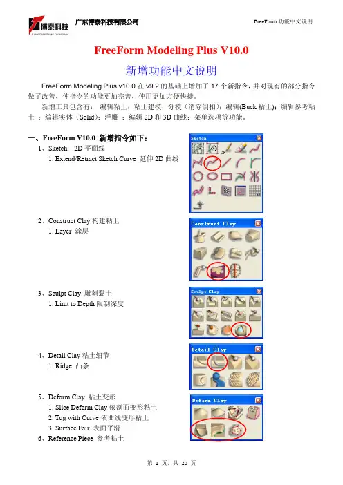
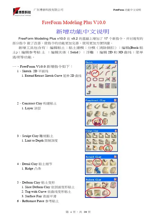
FreeForm软件教程-V10新增功能详解
Thickness – 在凸条底面延长一个厚度。
第 4 页,共 20 页
广东博泰科技有限公司
FreeForm 功能中文说明
勾选
不勾选
Profile Orientation 方向定位
Clay Surface
依粘土表面方向计算
Buck Surface
依 Buck 粘土表面方向计算
二、新增指令功能详细说明:
第 2 页,共 20 页
广东博泰科技有限公司
FreeForm 功能中文说明
Sketch:
1、
Extend/Retract Sketch Curve 延伸 2D 曲线
曲线的延伸方式
延长现有的曲线 延长的部分成另一条曲线
曲线长度
细部说明:
Tangent Reflection Curvature Tangent(to point)
缝合
不勾选时将在当前的参考粘土上进行缝合;勾选时将 Copy 一个参考粘土层 第 8 页,共 20 页
广东博泰科技有限公司
Example
FreeForm 功能中文说明
2、
Slice Deform Reference 依剖面变形“参考粘土”
注:(此指令用法同上,区别只是在于一个针对粘土,一个针对“参考粘土”,
3、
Plane to Clay Intersection Curve 粘土和平面求交线
软件自动计算编辑点数量
使用最大限度
直接设定编辑点数量
使用默认的控制点数量
使用最大限度
直接设定控制点数量
剖面公差
4、
Surface to Clay Intersection Curve 曲面和粘土求交线(其选项菜单同
咖啡杯的3D建模-FreeForm Modeling Plus软件教程
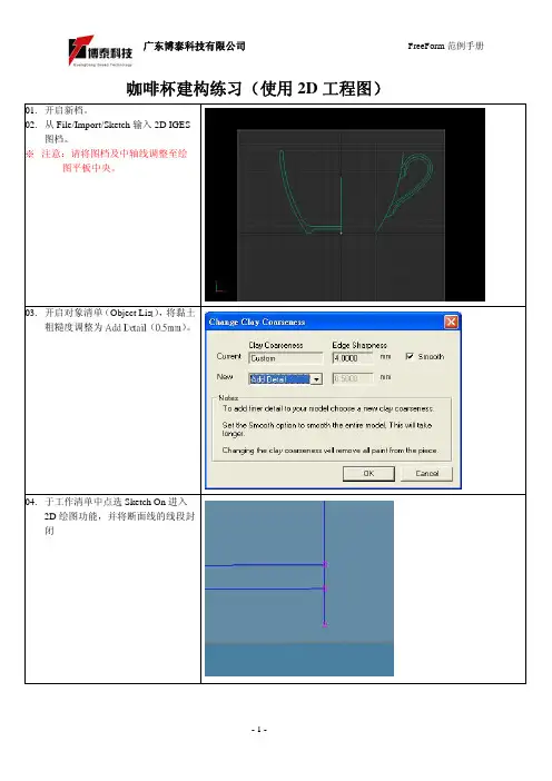
咖啡杯建构练习(使用2D工程图)01.开启新档。
02.从File/Import/Sketch输入2D IGES图档。
※注意:请将图档及中轴线调整至绘图平板中央。
03.开启对象清单(Object Lis t),将黏土粗糙度调整为Add Detail(0.5mm)。
04.于工作清单中点选Sketch On进入2D绘图功能,并将断面线的线段封闭05.点选Spin Clay功能,选择中轴线,再选择断面线将咖啡杯的杯身制作出来。
06.按F5切换至上视图,新增绘图平板,并于中心位置绘制一个正圆。
07.整理手把的2D线段,并将线段封闭。
08.使用Inflate功能,依据所需的手把宽度,将手把制作出来。
※请先点选Pieces\New Piece,选择创建一个空的粘土层。
09. 点选Sketch O n ,并在断面图中绘制两个圆圈状断面。
10. 点选SpinClay 功能,选择中轴线,再选择断面线将杯身上的圆环制作出来。
※ 请先点选Pieces\New Piece,选择创建一个空的粘土层。
11. 开启新的绘图板,并在两个圆环中绘制矩形线段。
12. 使用圈选工具,将矩形内的部份圈选下来。
13.选择Cut和Paste As New Piece将圆环拆成两个对象。
14.使用Tug变形功能,分别将上下两个圆环调整成麻花卷的造型。
※请记得开启轴向锁定功能。
15.使用Combine Into将组成麻花卷的两个圆环合并成一个对象。
16.开启新的绘图板,并在麻花卷中绘制矩形线段。
17.使用圈选工具,将矩形内的部份圈选下来。
18.按Ctrl加I执行反向选取,并点选delete将多余的数据删除。
19.使用圈选工具将麻花卷圈选下来。
20.执行Copy和Past e。
21.点选Paste Pattern。
22.接着再点选步骤06的数组轨迹。
23.请在对应工具列中输入所要数组复制的数量。
24.数量输入完后,请点选Add,以完成数组功能。
25.请在欲制作浮雕的3D模型表面上,使用3D Curve绘制浮雕的区域。
FreeFrom软件操作说明
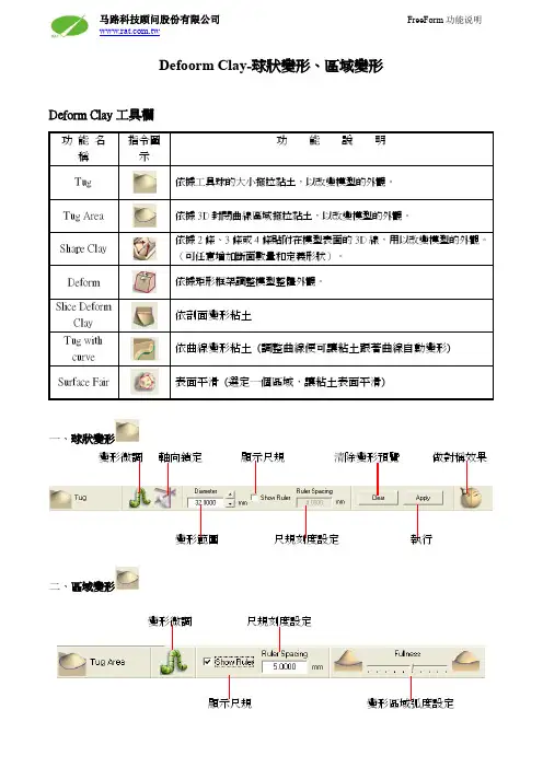
Defoorm Clay-球狀變形、區域變形
Deform Clay工具欄
一、球狀變形
變形微調軸向鎖定顯示尺規清除變形預覽做對稱效果
變形範圍尺規刻度設定執行
二、區域變形
變形微調尺規刻度設定
顯示尺規變形區域弧度設定
曲線定義造型
三、曲線定義造型
Shape Clay 指令是利用兩條、三條或四條封閉的3D 曲線,通過調整使用者定義的剖面,從而改變曲線區域內模型的形狀。
它可分為三個步驟進行: 1. 選擇邊界曲線 2. 指定剖面位置 3. 調整形狀
步驟一:選擇邊界曲線
步驟二:指定剖面位置
(快捷鍵Z)
(快捷X)
(快捷鍵C)
步驟三:調整形狀
框架定義變形
四、框架定義變形
框架定義模式 座標位置微調 同步鏡射調整 順化變形 進階調整 清除 確認
單方向調整 同方向調整 斜面變形 將框架調整和視角成水準
Advanced 進階調整選單:
順向調整 線性調整 分離調整
寬度設定
框架四周同步調整
剖面定義變形
五 、依剖面变形粘土
依剖面旋转变形
依曲线排列变形
六 、依曲线变形粘土
(调整曲线便可让粘土跟着曲线自动变形)
画曲线到鼻子和眉毛上面 执行指令后调整曲线,粘土将自动调整 注:使用此指令时,3D 曲线不能贴附粘土上。
七、 Surface Fair 表面平滑 (选定一个区域,让粘土表面平滑)。
FreeForm软件教程-V10新增功能详解
第 4 页,共 20 页
广东博泰科技有限公司
FreeForm 功能中文说明
勾选
不勾选
Profile Orientation 方向定位
Clay Surface
依粘土表面方向计算
Buck Surface
依 Buck 粘土表面方向计算
Current Pull Direction 依当前拔模方向计算
Parallel
Place slices at curveedit points - 根据曲线的编辑点产生 剖面。
Reset - 按重置以清除所有的数值,重新布 置剖面。 Create Slices - 创建剖面。
第 6 页,共 20 页
广东博泰科技有限公司
FreeForm 功能中文说明
Interpolated:
Construct Clay:
1、
Layer 涂层
设定厚度,用雕刻刀局部 Copy 外形(Copy 后与原有的粘土相连在同一物件)
Example
Sculpt Clay:
(Clay)粘土
(Buck)粘土
第 3 页,共 20 页
广东博泰科技有限公司
FreeForm 功能中文说明
1、
Linit to Depth 限制深度 (设定一个深度,方便在雕刻粘土时不会超过此深度)
广东博泰科技有限公司
1. Edit and Stitch Reference Piece 编辑参考粘土并缝合
2. Slice Deform Reference 依剖面变形参考粘土
3. Tug with Curve 依曲线变形参考粘土
7、 Patches / Solids 曲面/实体 1. Edit and Stitch Solid 编辑实体并缝合
FreeFrom软件操作说明
六、
Tug with Curve 依曲线变形“参考粘土”
半径 变形区域侧面的形状 高品质 微调 锁定轴向 取消 执行
指令圖 示
功
能
說
明
將選取的參考物件轉為黏土
將 3D 曲線范圍內參考物件轉換成黏土 编辑参考粘土并缝合 依剖面变形“参考粘土” 依曲线变形“参考粘土”
一、
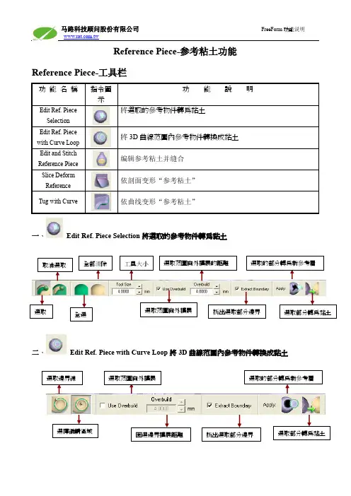
Edit Ref. Piece Selection 將選取的參考物件轉為黏土
取消選取
全部清除
工具大小
選考層
選取
马路科技顾问股份有限公司
FreeForm 功能说明
Reference Piece-参考粘土功能 Reference Piece-工具栏
功 能 名 稱
Edit Ref. Piece Selection Edit Ref. Piece with Curve Loop Edit and Stitch Reference Piece Slice Deform Reference Tug with Curve
FreeForm 功能说明
三、
选曲线
Edit and Stitch Reference Piece 编辑参考粘土并缝合
选粘土 设定粘土精度 粘土厚度 预留边界 转换粘土 选边界 选粘土 缝合
不勾选时将在当前的参考粘土上进行缝合;勾选时将 Copy 一个参考粘土层
Example
四、
Slice Deform Reference 依剖面变形“参考粘土” 注:(此指令用法同粘土,区别只是在于一个针对粘土,一个针对“参考粘土” , 详细功能说明请参考 此指令)。
全選
選取范圍向外擴展
析出選取部分邊界
選取部分轉為黏土
FreeForm V 新增功能说明 FreeForm Modeling lus软件教程
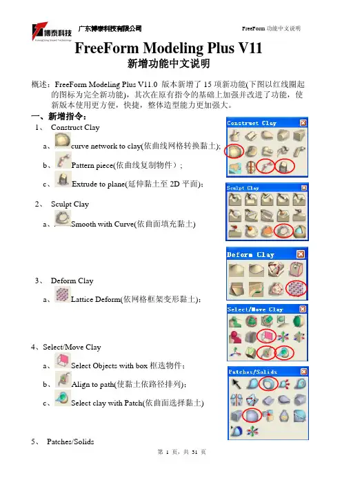
FreeForm Modeling Plus V11新增功能中文说明概述:FreeForm Modeling Plus V11.0 版本新增了15项新功能(下图以红线圈起的图标为完全新功能),其次在原有指令的基础上加强并改进了功能,使新版本使用更方便,快捷,整体造型能力更加强大。
一、新增指令:1、 Construct Claya、curve network to clay(依曲线网格转换黏土);b、Pattern piece(依曲线复制物件);c、Extrude to plane(延伸黏土至2D平面);2、 Sculpt Claya、Smooth with Curve(依曲面填充黏土)3、 Deform Claya、Lattice Deform(依网格框架变形黏土);4、Select/Move Claya、Select Objects with box框选物件;b、Align to path(使黏土依路径排列);c、Select clay with Patch(依曲面选择黏土)5、 Patches/Solidsa 、Create Ring Patch(依两条环形曲线建曲面);b 、Curve network to Solid(依曲线网格转换实体);6、Analysis Toolsa 、Analysze Fit (分析黏土贴附程度); b、Analysze Inter s ection (分析相交黏土); c 、Analysze Thickness (分析黏土厚度)d 、Dimensional Bounding Box (显示黏土的空间边界);e 、Ruler(3D 测试);二、新增指令功能详细说明:1、curve network to clay(依曲线网格转换黏土);2、Pattern piece(依曲线复制物件)微调旋转物体方向移动锁定轴向从曲线端点排列最后一个物件的比例生成新的图层旋转方式选择球珠和3D 线,设定球珠数量。
FreeFrom软件操作说明
19.右圖為使用 QuickTime VR 選項所運算出的結果。
马路科技顾问股份有限公司
FreeForm 功能说明
二、 在 2D 平面上定義背景圖片 貼圖檔名 贴图数量设定 渲染
貼圖路徑瀏覽
清除貼圖
※注意:指定貼圖之後,並無預覽功能,要執行 Render 之後才能看到貼圖影像。
08.點選
Custom Lighting 光源種類 光源開啟 光源色彩 倒影設定
進入光源設定選項。 09.光源設定的燈光種類共有 3 種: Point Light:點光源 Spot Light:聚光燈 Infinite Light:強光
马路科技顾问股份有限公司
FreeForm 功能说明
此種模式將會 render 出單張的影像檔,可儲存的格式 有 BMP、JPEG、TIFF 等常見的影像格式。
此種模式將不會進行 render 運算,而是將 3D 模型、材質 和燈光等設定值儲存為*.mi 的格式,讓使用者可以利用 Softimage 匯入此檔案而去進行 render 運算,使得 FreeForm 依然可以繼續建構 3D 模型的工作。
马路科技顾问股份有限公司
FreeForm 功能说明
Rendering-定義物件的材質及顏色、設定光源、場景設定、 設定渲染品質和解析度
Rendering 工具欄
功 能 名 稱 指令圖 示 Material Custom Lighting Display Scene Render Apply Texture to Rendering Plane
10.本範例所使用的光源種類 為聚光燈(Spot Light) 。
11.點選
Display Scene 進 場景種類 場景大小
龙型戒指设计-FreeForm Modeling Plus软件教程
戒指建构练习(使用2D影像)
01.开启新档。
02.从File/Import/Image输入2D
影像图文件的前视图
(Front.jpg)。
03.按F5切换至上视视角。
04.从File/Import/Image输入2D
影像图文件的侧视图
(Top.jpg)。
05.点选对象清单(Object List)中
的上视图以进入绘图模式,
并调整影像的尺寸及位置。
06.点选Edit Plane后,选择要操
作的平面,点选Sketch
on plane(K)进入2D画线功能07.在Top平面上绘制戒环的断
面线和中轴线。
08.将对象精度设定为Add
Detail。
09.使用Spin clay旋转功能,将
戒环基本形状制作出来。
※选择轮廓线,再选择中心轴,
执行Create Inside即可。
10.按F2切换至前视图。
11.点选Edit Plane将前视图移
动至正确位置。
>>>
1.选择全部。
2.复制戒环。
3.
执行
先描出封闭特征线。
FreeForm分模功能详细说明-FreeForm Modeling Plus软件教程
Mold DemoCreating Parting Line: Load the included Vampire Boy model.Go to Tab > Moldable PartCreate a parting line curve by activating the mold toolbar feature by selecting theMoldable Part tab. Then click on the Parting Line Curve icon on the toolbar andFreeform Mold Demo -1-click on the Show Parting Line Color icon to show the parting line. The arrow on the screen indicates the mold pull direction. You can change the direction by clicking onthe Set Direction icon to check the best parting line solution. Once everything is set, click on Apply to create the parting line curve.The parting line curve direction is already set for this model, but be sure the parting line draft angle is set to zero. To check if the draft angle is set to zero for this evaluation, go to Tools > Option > Parting line draft angle. For using the Parting Line tool, always set the draft to zero so that you will get a clear blue line. If the draft is not set to zero, the parting line curve will not be created in the correct location.Currently, the mold pull direction is already set correctly. If you want to show people the different pull direction, click on the Set Direction icon to change the setting.Showing Curvature PlotFreeform Mold Demo -2-The parting line curve is very dense and trying to pick up all the details necessary. If you want to look at the level of quality of the parting line curve, you can turn on the curvature plot and create a curvature plot of each curve. Go to:View > Design Curves -> Create Curvature Plots. Then click on the parting line curves on the model. By default, the plot is set in 2D to show the noise in Z direction only; you can also set to show the noise in X and Y direction by changing the 2D Curvature icon to 3D Curvature icon on the Dynabar. [as shown below]2D curvature plot showing on noise in Z directionFreeform Mold Demo -3-3D curvature plot showing noise in X and Y directionIn most cases, you will only want to use the 2D curvature plot in the Z direction. The number shown on the curvature plot indicates the minimum radius curvature of the curve. This number can be used to determine the tool size for machining in the future. To find the tool radius, simply take the inverse of the curvature value. The equation used in this calculation is shown below:C = 1/R ; C = curvature, R = radiusEditing Parting Line CurveFreeform Mold Demo -4-machining. To avoid this problem, I am going to smooth the parting line curve. Tosmooth the parting line curve, click on the Select icon on the toolbar and then clickon the parting line curve. Change the number on the Points box to reduce thenumber of points on the curve. In most cases, you can reduce the number of point by halfthen refit it. Be aware that it may have drifted from sharp details in the XY plane.Usually, after reducing the points on the parting line, the parting line will likely still be very close to the original parting line. However it does not work for every case. In most situations, you can just reduce the points and refit it just for demo purposes.Now I will refit the parting line curve by clicking on the Fit CurveFreeform Mold Demo -5-to Clay tool under the same flyout as the Parting Line Curve tool. Then click on the parting line curve. Refitting the curve will remove the curvature plot information because the refitted curve is actually a new curve. Therefore, you have to put the curvature plot back on to see the new result. Now you can see that the refitted curves have a low curvature and noise.You can also use the Smooth Curve tool under the Parting Line Curve tool to smooth out the curves. After you are satisfied with the result, you can turn off the curvature plot.Fixing DraftFor this model, there is a draft problem. To demonstrate the draft-fixing feature, youFreeform Mold Demo -6-should point out some draft problems on the model. Indicate the areas behind the nose and the teeth (Create Parting Line actually surrounded these areas with curves, which can be deleted at this time.)The next thing to do is to fix draft. As you can see on the screen, the nose and the tooth have a draft issue. To correct the problem, I can either add material or remove material to correct the problem under the Draft option.Go back to create moldable part and then select Draft tool on the toolbar. Then click on the parting line. The problem areas are shown in blue. Now I want to add material behind the nose to the fix the draft instead of chopping off the nose to fix the draft. So I click on the Add Clay , but hold to the parting line by clicking thePreserver Parting line icon then click Apply.The changes on the model should be very quick, so you can say a few words or gesturing with your hands, then the changes should be done. The fixed model is shown below.Freeform Mold Demo -7-Shelling The ModelClick on the “d” key to show the model in See Through mode, and indicate that it is a solid model. Click the “d” key once more to return to an opaque view.Now you can shell the model. Click on Shell on the toolbar. For this model, I want a 4mm shell. Then change the number in the Shell Thickness box on the dynabarto 4 and click Apply.Freeform Mold Demo -8-The shelling process should be done very quickly. While waiting for the model to be shelled, you can talk about the benefit of this feature. After the shell is complete, click on “d” on the keyboard again to activate the dotted mode for showing the part thickness.Click “d” to change to dotted mode to show part thicknessYou can check the part thickness by using the ruler feature. Go to Tools > Ruler or click“r” on the keyboard to activate the ruler feature. Then select Measure Thicknessicon on the Dynabar and measure the part thickness.Freeform Mold Demo -9-Creating Split JointFor better visual, turn off the clay by clicking on Blank Clay icon. The resulting screen is shown above. By turning off the clay, you can see the glue joint that you will create on the screen.Now I want to be able to create the shiplap joint. I go down to the Split Joint tool and pick on the curve on the screen. It will create a butt joint by default first (shown below) then I will create a shiplap joint on the modelFreeform Mold Demo -10-.After selecting the curve on the screen, a butt joint will be created. The creation of butt joint will not fail on this model. The shiplap joint properties box will pop up automatically when the butt joint is created.On the ShipLap Joint Properties box, set the values on the boxes to:-Offset value to 2mm because it’s a 4mm shiplap-Depth value to 2.5mm, just high enough that people can see the difference -Angle value to 5 degree so that it looks like in a angleFreeform Mold Demo -11-Ensure the Modify Region icon is selected on the dynabar then click on any two points on the outside curve of the model to define the region of the joint then click on any place on the curve within the region to create the split joint (as shown above).For the demo, create shiplap joint at only one place because for every place you do, you have to be able to select the inside curve of the split joint in the middle of the demo when you are doing Make Part and Make Insert. Therefore, to shorten the demo time and keep the audience’s attention, avoid creating more than one split joint.Next you want to show the Groove split joint feature, make an undo after the shiplap joint is created. Then select Groove Joint icon and the Groove Joint Properties box will appear.Freeform Mold Demo -12-Make sure the sum of the Offset value and the Width value does not exceed the width of the split joint, which is 4mm in this case. Otherwise, you will receive an error message. Once the values are entered, ensure the Create Split Joint icon is selected on the dynabar to create a groove joint on the entire curve. Then select the curve on the screen and a Groove Joint will be created (shown as below)Creating the groove joint for the demo is easier for the Make Part step later in the demo because you don’t have to pick the separate section all the way around the curve.Freeform Mold Demo -13-Freeform Mold Demo -14-Making PartNow I will separate the model into 2 parts, part 1 and part 2. I go to the Make Particon on the toolbar. Then select the Split Curve icon on the dynabar and click on the first split joint then the second split joint of the part. Next I click on the Part 1 Sideicon and click on the outside of the model(the face in this example) to select what is going to the part 1.When selecting the part 1 side, uncheck the Blank Clay to show the whole piece of clay. It’s easier in this way.Freeform Mold Demo -15-The first split joint is the outside curve of the part and the second split joint is the inside curve of the partThe first split joint is highlighted inFreeform Mold Demo -16-The second split joint is highlighted in green as shown on the rightnow look at the other part by selecting Work on Part of the other part in the Object List.Freeform Mold Demo -17-To turn on the object list, either click “o” on the keyboard or go to View > Object listOn the Object List, click on the part icon, and select Work On Part option to select the part that you want to work on.For the rest of the demo, we will work on one part of the model, Part 1 the face, though the other Part 2 can be done in a similar way.Freeform Mold Demo -18-Creating Mold InsertSo the next thing I will create an extent for the part, that is defining the actual mold insert dimensions, and create parting surfaces for the model.The extents can be resized to any dimension you need to fit into the mold. To resize it, you go to the set extents option (which is usually active when first entering the Mold Insert tab) and enter the XYZ values for the extents.To resize the extent, click on Create Mold Insert tab on the top of the workspace thenselect Mold Insert Properties and click on Set Extents icon on the Dynabar. Enter the desired dimension for the extent on the X,Y,Z boxes. For the demo, show people that the extent can be changed and set the numbers in the X,Y,Z boxes to a reasonable numbers. The following numbers are used for this demo:+X = 100.00, -X = -100.00+Y = 150.00, -Y = -150.00Freeform Mold Demo -19-+Z = 100.00, -Z = -100.00Freeform Mold Demo -20-Creating Extruded Parting SurfaceNext I will create the parting surfaces for the part. I go to the Extrude Parting Surfacetool then pick on two places on the curve to define the boundary. When you are picking the points to define the boundary, you don’t have to pick on the points, you can pick anywhere on the curve. The extruded surface can be created in a 45 degree angle. When extruding the surfaces from this example, extrude the surfaces perpendicularly from the form. For example, extrude it in a horizontal or vertical direction.Freeform Mold Demo -21-Creating Insert BlocksAfter the parting surface is completed, I will create a core insert block and a cavity insert blocks for the part. This can be done in a few steps.First I go to the Make Insert Blocks tool on the toolbar. Second, I pick the edge of the parting surface and the parting line. Finally, I select the side for the cavity block. To create insert blocks for the part:-Click on Parting Surface Curve icon on the Dynabar and select the edge of the extruded surface-Then select the parting line of the model (as shown below in green)Freeform Mold Demo -22--Click on Cavity Side icon on the dynabar and select the cavity side of the model.-Once the cavity side is selected, a plane will appear on the screen to represent the bottom of the cavity block.o Notes: Don’t zoom to close to the model; otherwise you will not be able to see the plane.o Notes: If you selected the top part as the cavity side, then the plane should be placed on the topside or on the bottom side if the bottom part isselected as the cavity side.- A window will pop up and asks if the plane is placed correctly, click “Yes” if the plane location is correct or “No” if the plane location is incorrect…Freeform Mold Demo -23-shown below)…Freeform Mold Demo -24-From here, I have two insert blocks, one for the core and the other one for the cavity. I can look at either one of the blocks by selecting it on the Object List.To look at the core block:-Turn on the object list and click on the core mold insert icon, and select Work On Component option-This will hide the cavity side component automatically.Freeform Mold Demo -25-Freeform Mold Demo -26-You can turn off “See Through Clay” option by View > Design Curve > See Through Clay for people easier to see to blockFreeform Mold Demo -27-Reverse Engineering the Core FaceThe next thing I will do is to create patch surface for the core. After I create the patches, I can export the file to other CAD software to build other components on the mold insert such as runners systems, water lines, sprues, and ejection pins, etc. To create the patch, I draw curves that defined the patch boundary on the core. Then using the Patch toolon the toolbar to create the batch surfaces for the core.Freeform Mold Demo -28-To draw curves defining the patch boundary on the core:-Select Draw tool under Parting Line tool-Ensure the Fit on Create icon is selected on the dynabaro Notes: DO NOT select Split on Create icon on the dynabar because it will destroy the surfaces by separating the curve into two-Turn on See Through Clay option by: View > Design Curves > See Through Clay (if you find it to be easier).-Start drawing curve on the model to cover up the entire core (as shown above)Freeform Mold Demo -29-To create patches on the core surface:-Once the curves are drawn on the surface, select the Patch tool-Ensure Fit to Clay and Manual Boundary Select icons are selected on the dynabaro Notes: Selecting the Fit to Clay icon will create patches that are more tightly fitted on the clay surface than using the Fit to Boundary icon . -Click on the curves in sequence to define the boundary of the patch. Once you are done the patches, go to the object list and folder the patches you create and label the folder something meaningful. You will need to refer to this folder later.Freeform Mold Demo -30-Exporting IGESOnce the Core side of Part 1 is patched, it can be exported as an IGES file for further modification in other CAD software.To export an IGES file of the Core side:Go to File > Export > Curves and Patches, then check the following information in the dialog box that appears:Freeform Mold Demo -31-…which will write an IGES file for CAD import. To export an STLfile of each of the blocks of the insert, for rapid prototyping:For the core, turn off the display of all Clay and Curves using the lower left display control:Then go to File > Export > Model, then, it will export the patches which will be subdivided to create polygons out of the patches.Usually, the default has adequate details when exporting the STL polygon file but if you want more detail, go to Patch Display Properties under the Blank Patches icon onFreeform Mold Demo -32-the Dynabar.Freeform Mold Demo -33-Changing the Display Resolution to High in thePatch Display Properties will give you a muchfiner tessellation of the patches.You can verify your results by reading the fileback in as an STL import and preview (but don’tkeep it, just preview it as below…Note: When exporting the Cavity side, you don’t want the Split Joint patches or the core face patches visible. On the Object list, do a “work on component” on the cavity component first, then hide the Split Joint Curves and Split Joint Patches folders as shown on the right. Find the folder you created for the Core face reverse engineering patches and hide it as well.Creating ElectrodeCreating electrode off the cavity is not something that is automatically created but it is not too difficult to do. First you want to turn off the surfaces and build a plane to project the parting line onto the plane. Then draw a line to connect the curves and create a patch for the side. Once the patch is created, export it as an electrode.To Create Electrode Off the Back Cavity Block:Go to the Object list then turn off the surfaces of the core and cavity blocks and the parting surfaces as shown below.Then select New Plane/Sketch on the toolbar to create a plane. The distance between the part and the plane is equal to the distance of the side of the electrode.Select Project Curve to Plane from the flyout of the Parting line curve tool on the toolbar. Then click on the parting line curves and touch the plane. The curves will then be projected onto the plane (as shown below). Once the curve is projected, you can hide the plane on the object list.Freeform Mold Demo -34-Next select Draw from the Parting line curve tool on the toolbar. Make sure the Fit on Create icon on the dynabar is deselected because you want to make a square patch. Then draw a line connected the parting line and the projected parting line.For this model, a patch can be built with only two main curve segments (as shown below)Freeform Mold Demo -35-Freeform Mold Demo -36-dynabar so that a straight extrusion can be created. Then select the curves in sequence to create the patches (as shown below)Once the side patches are created, you can make a patch for the back but for electrodes the back patch is not required. Then export it as an STL file for tooling the electrode.。
小狗FreeForm画图-FreeForm Modeling Plus软件教程
Smooth Area
*再用 Smooth Area 将尖角部分 平顺化。
*然后用
Tug 指令调整形状。
04*利用 Add clay 制作一个与身
Add clay
体差不大小的圆柱,再用
Smooth Area+ 调整大概形状。
Tug 指令
Combine 05*执行 Combine 将头部和身m 范例手册
概述:
此范例是依据一些 2D 的照片制作的,依据照片建构 3D 模型
时,用传统的制作方法需要很多步骤,且造型复杂的曲面及表面
皮毛的部分做起来既费时又费力,其效果也是有限的,现在,有
了 FreeForm 一切就变得简单而又快速了,制作类似这样的可爱小
动物时 FreeForm 或 FreeForm Concept 就是您最佳的工具。
第 1 页,共 5 页
广东博泰科技有限公司
01*点击 Create Plane 创建 2D 平面。
Create Plane
*点击 Sketch on Plane 进入 2D 界 面。
*执行(File>Import >Image)将照片导 入至每个视角对应的 2D 平面上并 进行定位,然后缩放图片的尺寸(狗 仔长度为 100mm)。
FreeForm 范例手册
FreeForm 制作的 Rendering Image.
第 5 页,共 5 页
Emboss with
Wrapped
*
用 Smudge 工具由内往外磨,
让脚趾更饱满。
*提示:另外三只脚和尾巴作法同上,
先增加一个简单的如圆柱等,再用
变形工具调整细部形状。
14*建构完成后用浮雕功能制作身上的
- 1、下载文档前请自行甄别文档内容的完整性,平台不提供额外的编辑、内容补充、找答案等附加服务。
- 2、"仅部分预览"的文档,不可在线预览部分如存在完整性等问题,可反馈申请退款(可完整预览的文档不适用该条件!)。
- 3、如文档侵犯您的权益,请联系客服反馈,我们会尽快为您处理(人工客服工作时间:9:00-18:30)。
Mold DemoCreating Parting Line: Load the included Vampire Boy model.Go to Tab > Moldable PartCreate a parting line curve by activating the mold toolbar feature by selecting theMoldable Part tab. Then click on the Parting Line Curve icon on the toolbar andFreeform Mold Demo -1-click on the Show Parting Line Color icon to show the parting line. The arrow on the screen indicates the mold pull direction. You can change the direction by clicking onthe Set Direction icon to check the best parting line solution. Once everything is set, click on Apply to create the parting line curve.The parting line curve direction is already set for this model, but be sure the parting line draft angle is set to zero. To check if the draft angle is set to zero for this evaluation, go to Tools > Option > Parting line draft angle. For using the Parting Line tool, always set the draft to zero so that you will get a clear blue line. If the draft is not set to zero, the parting line curve will not be created in the correct location.Currently, the mold pull direction is already set correctly. If you want to show people the different pull direction, click on the Set Direction icon to change the setting.Showing Curvature PlotFreeform Mold Demo -2-The parting line curve is very dense and trying to pick up all the details necessary. If you want to look at the level of quality of the parting line curve, you can turn on the curvature plot and create a curvature plot of each curve. Go to:View > Design Curves -> Create Curvature Plots. Then click on the parting line curves on the model. By default, the plot is set in 2D to show the noise in Z direction only; you can also set to show the noise in X and Y direction by changing the 2D Curvature icon to 3D Curvature icon on the Dynabar. [as shown below]2D curvature plot showing on noise in Z directionFreeform Mold Demo -3-3D curvature plot showing noise in X and Y directionIn most cases, you will only want to use the 2D curvature plot in the Z direction. The number shown on the curvature plot indicates the minimum radius curvature of the curve. This number can be used to determine the tool size for machining in the future. To find the tool radius, simply take the inverse of the curvature value. The equation used in this calculation is shown below:C = 1/R ; C = curvature, R = radiusEditing Parting Line CurveFreeform Mold Demo -4-machining. To avoid this problem, I am going to smooth the parting line curve. Tosmooth the parting line curve, click on the Select icon on the toolbar and then clickon the parting line curve. Change the number on the Points box to reduce thenumber of points on the curve. In most cases, you can reduce the number of point by halfthen refit it. Be aware that it may have drifted from sharp details in the XY plane.Usually, after reducing the points on the parting line, the parting line will likely still be very close to the original parting line. However it does not work for every case. In most situations, you can just reduce the points and refit it just for demo purposes.Now I will refit the parting line curve by clicking on the Fit CurveFreeform Mold Demo -5-to Clay tool under the same flyout as the Parting Line Curve tool. Then click on the parting line curve. Refitting the curve will remove the curvature plot information because the refitted curve is actually a new curve. Therefore, you have to put the curvature plot back on to see the new result. Now you can see that the refitted curves have a low curvature and noise.You can also use the Smooth Curve tool under the Parting Line Curve tool to smooth out the curves. After you are satisfied with the result, you can turn off the curvature plot.Fixing DraftFor this model, there is a draft problem. To demonstrate the draft-fixing feature, youFreeform Mold Demo -6-should point out some draft problems on the model. Indicate the areas behind the nose and the teeth (Create Parting Line actually surrounded these areas with curves, which can be deleted at this time.)The next thing to do is to fix draft. As you can see on the screen, the nose and the tooth have a draft issue. To correct the problem, I can either add material or remove material to correct the problem under the Draft option.Go back to create moldable part and then select Draft tool on the toolbar. Then click on the parting line. The problem areas are shown in blue. Now I want to add material behind the nose to the fix the draft instead of chopping off the nose to fix the draft. So I click on the Add Clay , but hold to the parting line by clicking thePreserver Parting line icon then click Apply.The changes on the model should be very quick, so you can say a few words or gesturing with your hands, then the changes should be done. The fixed model is shown below.Freeform Mold Demo -7-Shelling The ModelClick on the “d” key to show the model in See Through mode, and indicate that it is a solid model. Click the “d” key once more to return to an opaque view.Now you can shell the model. Click on Shell on the toolbar. For this model, I want a 4mm shell. Then change the number in the Shell Thickness box on the dynabarto 4 and click Apply.Freeform Mold Demo -8-The shelling process should be done very quickly. While waiting for the model to be shelled, you can talk about the benefit of this feature. After the shell is complete, click on “d” on the keyboard again to activate the dotted mode for showing the part thickness.Click “d” to change to dotted mode to show part thicknessYou can check the part thickness by using the ruler feature. Go to Tools > Ruler or click“r” on the keyboard to activate the ruler feature. Then select Measure Thicknessicon on the Dynabar and measure the part thickness.Freeform Mold Demo -9-Creating Split JointFor better visual, turn off the clay by clicking on Blank Clay icon. The resulting screen is shown above. By turning off the clay, you can see the glue joint that you will create on the screen.Now I want to be able to create the shiplap joint. I go down to the Split Joint tool and pick on the curve on the screen. It will create a butt joint by default first (shown below) then I will create a shiplap joint on the modelFreeform Mold Demo -10-.After selecting the curve on the screen, a butt joint will be created. The creation of butt joint will not fail on this model. The shiplap joint properties box will pop up automatically when the butt joint is created.On the ShipLap Joint Properties box, set the values on the boxes to:-Offset value to 2mm because it’s a 4mm shiplap-Depth value to 2.5mm, just high enough that people can see the difference -Angle value to 5 degree so that it looks like in a angleFreeform Mold Demo -11-Ensure the Modify Region icon is selected on the dynabar then click on any two points on the outside curve of the model to define the region of the joint then click on any place on the curve within the region to create the split joint (as shown above).For the demo, create shiplap joint at only one place because for every place you do, you have to be able to select the inside curve of the split joint in the middle of the demo when you are doing Make Part and Make Insert. Therefore, to shorten the demo time and keep the audience’s attention, avoid creating more than one split joint.Next you want to show the Groove split joint feature, make an undo after the shiplap joint is created. Then select Groove Joint icon and the Groove Joint Properties box will appear.Freeform Mold Demo -12-Make sure the sum of the Offset value and the Width value does not exceed the width of the split joint, which is 4mm in this case. Otherwise, you will receive an error message. Once the values are entered, ensure the Create Split Joint icon is selected on the dynabar to create a groove joint on the entire curve. Then select the curve on the screen and a Groove Joint will be created (shown as below)Creating the groove joint for the demo is easier for the Make Part step later in the demo because you don’t have to pick the separate section all the way around the curve.Freeform Mold Demo -13-Freeform Mold Demo -14-Making PartNow I will separate the model into 2 parts, part 1 and part 2. I go to the Make Particon on the toolbar. Then select the Split Curve icon on the dynabar and click on the first split joint then the second split joint of the part. Next I click on the Part 1 Sideicon and click on the outside of the model(the face in this example) to select what is going to the part 1.When selecting the part 1 side, uncheck the Blank Clay to show the whole piece of clay. It’s easier in this way.Freeform Mold Demo -15-The first split joint is the outside curve of the part and the second split joint is the inside curve of the partThe first split joint is highlighted inFreeform Mold Demo -16-The second split joint is highlighted in green as shown on the rightnow look at the other part by selecting Work on Part of the other part in the Object List.Freeform Mold Demo -17-To turn on the object list, either click “o” on the keyboard or go to View > Object listOn the Object List, click on the part icon, and select Work On Part option to select the part that you want to work on.For the rest of the demo, we will work on one part of the model, Part 1 the face, though the other Part 2 can be done in a similar way.Freeform Mold Demo -18-Creating Mold InsertSo the next thing I will create an extent for the part, that is defining the actual mold insert dimensions, and create parting surfaces for the model.The extents can be resized to any dimension you need to fit into the mold. To resize it, you go to the set extents option (which is usually active when first entering the Mold Insert tab) and enter the XYZ values for the extents.To resize the extent, click on Create Mold Insert tab on the top of the workspace thenselect Mold Insert Properties and click on Set Extents icon on the Dynabar. Enter the desired dimension for the extent on the X,Y,Z boxes. For the demo, show people that the extent can be changed and set the numbers in the X,Y,Z boxes to a reasonable numbers. The following numbers are used for this demo:+X = 100.00, -X = -100.00+Y = 150.00, -Y = -150.00Freeform Mold Demo -19-+Z = 100.00, -Z = -100.00Freeform Mold Demo -20-Creating Extruded Parting SurfaceNext I will create the parting surfaces for the part. I go to the Extrude Parting Surfacetool then pick on two places on the curve to define the boundary. When you are picking the points to define the boundary, you don’t have to pick on the points, you can pick anywhere on the curve. The extruded surface can be created in a 45 degree angle. When extruding the surfaces from this example, extrude the surfaces perpendicularly from the form. For example, extrude it in a horizontal or vertical direction.Freeform Mold Demo -21-Creating Insert BlocksAfter the parting surface is completed, I will create a core insert block and a cavity insert blocks for the part. This can be done in a few steps.First I go to the Make Insert Blocks tool on the toolbar. Second, I pick the edge of the parting surface and the parting line. Finally, I select the side for the cavity block. To create insert blocks for the part:-Click on Parting Surface Curve icon on the Dynabar and select the edge of the extruded surface-Then select the parting line of the model (as shown below in green)Freeform Mold Demo -22--Click on Cavity Side icon on the dynabar and select the cavity side of the model.-Once the cavity side is selected, a plane will appear on the screen to represent the bottom of the cavity block.o Notes: Don’t zoom to close to the model; otherwise you will not be able to see the plane.o Notes: If you selected the top part as the cavity side, then the plane should be placed on the topside or on the bottom side if the bottom part isselected as the cavity side.- A window will pop up and asks if the plane is placed correctly, click “Yes” if the plane location is correct or “No” if the plane location is incorrect…Freeform Mold Demo -23-shown below)…Freeform Mold Demo -24-From here, I have two insert blocks, one for the core and the other one for the cavity. I can look at either one of the blocks by selecting it on the Object List.To look at the core block:-Turn on the object list and click on the core mold insert icon, and select Work On Component option-This will hide the cavity side component automatically.Freeform Mold Demo -25-Freeform Mold Demo -26-You can turn off “See Through Clay” option by View > Design Curve > See Through Clay for people easier to see to blockFreeform Mold Demo -27-Reverse Engineering the Core FaceThe next thing I will do is to create patch surface for the core. After I create the patches, I can export the file to other CAD software to build other components on the mold insert such as runners systems, water lines, sprues, and ejection pins, etc. To create the patch, I draw curves that defined the patch boundary on the core. Then using the Patch toolon the toolbar to create the batch surfaces for the core.Freeform Mold Demo -28-To draw curves defining the patch boundary on the core:-Select Draw tool under Parting Line tool-Ensure the Fit on Create icon is selected on the dynabaro Notes: DO NOT select Split on Create icon on the dynabar because it will destroy the surfaces by separating the curve into two-Turn on See Through Clay option by: View > Design Curves > See Through Clay (if you find it to be easier).-Start drawing curve on the model to cover up the entire core (as shown above)Freeform Mold Demo -29-To create patches on the core surface:-Once the curves are drawn on the surface, select the Patch tool-Ensure Fit to Clay and Manual Boundary Select icons are selected on the dynabaro Notes: Selecting the Fit to Clay icon will create patches that are more tightly fitted on the clay surface than using the Fit to Boundary icon . -Click on the curves in sequence to define the boundary of the patch. Once you are done the patches, go to the object list and folder the patches you create and label the folder something meaningful. You will need to refer to this folder later.Freeform Mold Demo -30-Exporting IGESOnce the Core side of Part 1 is patched, it can be exported as an IGES file for further modification in other CAD software.To export an IGES file of the Core side:Go to File > Export > Curves and Patches, then check the following information in the dialog box that appears:Freeform Mold Demo -31-…which will write an IGES file for CAD import. To export an STLfile of each of the blocks of the insert, for rapid prototyping:For the core, turn off the display of all Clay and Curves using the lower left display control:Then go to File > Export > Model, then, it will export the patches which will be subdivided to create polygons out of the patches.Usually, the default has adequate details when exporting the STL polygon file but if you want more detail, go to Patch Display Properties under the Blank Patches icon onFreeform Mold Demo -32-the Dynabar.Freeform Mold Demo -33-Changing the Display Resolution to High in thePatch Display Properties will give you a muchfiner tessellation of the patches.You can verify your results by reading the fileback in as an STL import and preview (but don’tkeep it, just preview it as below…Note: When exporting the Cavity side, you don’t want the Split Joint patches or the core face patches visible. On the Object list, do a “work on component” on the cavity component first, then hide the Split Joint Curves and Split Joint Patches folders as shown on the right. Find the folder you created for the Core face reverse engineering patches and hide it as well.Creating ElectrodeCreating electrode off the cavity is not something that is automatically created but it is not too difficult to do. First you want to turn off the surfaces and build a plane to project the parting line onto the plane. Then draw a line to connect the curves and create a patch for the side. Once the patch is created, export it as an electrode.To Create Electrode Off the Back Cavity Block:Go to the Object list then turn off the surfaces of the core and cavity blocks and the parting surfaces as shown below.Then select New Plane/Sketch on the toolbar to create a plane. The distance between the part and the plane is equal to the distance of the side of the electrode.Select Project Curve to Plane from the flyout of the Parting line curve tool on the toolbar. Then click on the parting line curves and touch the plane. The curves will then be projected onto the plane (as shown below). Once the curve is projected, you can hide the plane on the object list.Freeform Mold Demo -34-Next select Draw from the Parting line curve tool on the toolbar. Make sure the Fit on Create icon on the dynabar is deselected because you want to make a square patch. Then draw a line connected the parting line and the projected parting line.For this model, a patch can be built with only two main curve segments (as shown below)Freeform Mold Demo -35-Freeform Mold Demo -36-dynabar so that a straight extrusion can be created. Then select the curves in sequence to create the patches (as shown below)Once the side patches are created, you can make a patch for the back but for electrodes the back patch is not required. Then export it as an STL file for tooling the electrode.。