
110i详细使用说明
110i详细使用说明
一、开启
1)将专用数据充电线连接110i接入电源充电(可使用电脑的USB端口、5V/1A的移动电源、手机充电器头均可),充电完毕后即可按压机身左下角【MODE】按键2秒开机。
*建议首次充电时长满两小时以保持电池活力
2)开机页面后→进入【语言选项】→【时区选项】,完成后自动进入搜星状态。
(卫星定位需要在室外无阻挡的空旷地)。
二、软件下载
1)电脑下载
打开网页: (GOLiFE官网)→首次打开此网页的用户,选择“简体中文”版网站→点击右上角【软件下载】选择适合需求的GoWatch 110i的软件
2)安卓下载
方法1:手机浏览器打开网页: 【GOLiFE官网】→首次打开此网页的用户,选择【简体中文】版网站→点击APP/软件下载→选择【GoWatch 110i Android】点击下载。
方法2:打开各大应用市场:360、百度、小米、魅族等→搜索:【GOLiFE RUN】点击下载。
3)IOS下载
打开【App store】→搜索【GOLiFE RUN】点击下载。
注:固件更新需打开网页: (GOLiFE官网)→首次打开此网页的用户,选择“简体中文”版网站→点击右上角【软件下载】选择适合需求的GoWatch 110i 的【计算机专用电脑软件】→用数据线将手表与电脑连接,打开电脑软件→新用户请点击【立即注册】/老用户可直接输入账号密码登录→点击【更新产品韧体】
三、登录及手表配对(手表配对需确保手机蓝牙保持开启状态)
1)下载安装完毕后打开【GOLiFE RUN】APP,可使用邮箱注册登录或者使用第三方合作账号登录(微博、facebook)。
★★★推荐邮箱注册登录,GOLiFE会在每周、每月结束后给用户邮箱发送健康报告。
2)登录页面
此页面可设定:昵称性别、生日、单位、身高、体重。
3)配对
时间模式下,按压手表左下【MODE及开关键】进入功能选单→按压右上/下键选择【蓝牙配对】→选择【是】开始配对→手机软件【GOLiFE RUN】界面点击左上角菜单图标打开菜单→点击【我的设备】→点击右上角的【+】号→选择【GoWatch 110i】→点击【已开启配对模式】→【开始配对】→手机与手表靠近→手机上输入手表出现的配对码→完成配对。
四、日常运动
1)按压左下角【MODE键】进入【开始运动】→右中【OK键】选择功能(包括跑步、自行
车、登山、步行、全马、半马、游泳、室内跑步、室内骑车、其他、训练员、交互训练)2)选择模式后进入搜星界面(若点击直接开始,轨迹会按照搜星成功定位时刻开始,易造成轨迹偏差)
3)搜星成功后进入数据显示界面,可按压【右上、下两键】翻页查看数据,右中键【OK 键】可开始/暂停运动
4)运动结束后,按压右中【OK键】选择【结束并储存】或【放弃】处理运动记录。
(保存数据后同步即可在APP左上角菜单键选择【我的活动】点击相应活动查看数据及轨迹或访问网页【/】登录后查看)
五、功能选项
1)活动
时间模式下,按【MODE】键进入选单模式,选择【活动】。
此页面可查看:活动记录、活动设置、内存使用、删除所有运动记录。
*(活动设置,此页面可以自定义:步频训练器、自动暂停设置、提示设置、自动圈数设置、记录间隔设置。
)
2)日常监控
时间模式下,按左下角【MODE键】进入功能选单→右上下键选择【日常监控】→可选择【计步】及【信息提示】的开启/关闭(可在【GOLiFE RUN】中选择110i设定每日目标步数)
3)系统设置
时间模式下,按【MODE键】进入功能选单→选择【系统设置】
1、个人信息
英文姓名、性别、年龄、身高、体重、轮径、步幅。
(此页面的参数会跟室内跑步、骑车、室内骑车等功能的数据有关联,请准确填写)
2、页面设置
此页面可自由设定:页面1、页面2、页面3、页面4、圈数页面。
每页显示的数据资讯数目(选择页面时也可按【OK键】自定义设定每页显示的具体数据,如配速、心率等)
3、电子罗盘
校准及磁偏角设置(输入相对数值,手表将会根据相对值重新校准减小误差)
4、单位
公制、英制
5、时间模式
时钟风格、时间格式12/24小时制、时区、日光节约、校准、时间设置
6、显示设置
背光、语言选择、背景颜色、手表待机(待机结束后会自动关闭GPS定位,进入纯显示时间的手表模式)、智能亮屏、智能休眠。
7、音效
按键/信息,提示音开启与关闭。
9、振动
10、闹钟设置
11、还原(恢复出厂设置)
12、产品讯息(固件版本号信息)
6)蓝牙
时间模式下,按左下角【MODE键】进入功能选单→右上下键选择【蓝牙同步】或【蓝牙配对】
1、蓝牙同步:进入【蓝牙同步】开始同步→手机开启蓝牙进入【GOLiFE RUN】选择110i→点击【同步信息】→点击【已开启同步模式】→【开始同步】→手机与手表保持近距离将会出现同步进度条至同步完成
2、配对模式:进入【蓝牙配对】→选择【是】开始配对→手机软件【GOLiFE RUN】界面点击左上角菜单图标打开菜单→点击【我的设备】→点击右上角的【+】号→选择【GoWatch 110i】→点击【已开启配对模式】→【开始配对】→手机与手表靠近→手机上输入手表出现的配对码→完成配对
7)装置配对
时间模式下,按左下角【MODE键】进入功能选单→右上下键选择【装置配对】→即可配对【心率带】或【踏频速度器】(ANT+协议的外置装置均可配对使用)*心率带配对:电池电量充足的情况下,将心率带贴身佩戴或用手按压→点击【心率带】靠近手表进行配对(若配对失败按右下键【重新配对】)
六、按键便捷功能
1)左上【LAP/C】:长按五秒即可锁机/解锁
2)右中【OK键】:电子罗盘
3)右下键:信息、来电内容详情显示。
佳能 IXUS 110 IS 數碼相機使用者指南说明书

相機使用者指南數碼相機相機使用者指南© CANON INC. 2009PRINTED IN HONG KONG 商標聲明•SDHC 標誌為商標。
•HDMI 、HDMI 標誌及高清多媒體介面為HDMI Licensing LLC 的商標或註冊商標。
免責聲明•未經佳能公司授權前,本手冊的任何部份均不得被複製、傳輸或儲存於可檢索之系統中。
•佳能公司保留權利可隨時變更本指南的內容而無須事先聲明。
•本指南的圖片及螢幕示範可能與器材實際所顯示的稍有不同。
•本書編製過程中已力求內容的正確與完整,但如您發現任何錯誤或漏失,請聯絡隨產品提供佳能客戶支援單張上的佳能客戶服務中心。
•除上述事項外,佳能公司對於因操作產品不當而導致的損壞概不負責。
•使用相機之前,請先閱讀本指南。
•請妥善存放本指南,以供日後參考。
如有任何印刷錯漏或翻譯上的誤差,望廣大用戶諒解。
產品設計與規格如有更改,恕不另行通知。
2請檢查您的相機包裝內是否包含下列物品。
如發現物品不齊全,請聯絡您購買相機的零售商。
檢查包裝內容相機電池NB-4L(附端子蓋)介面連接線IFC-400PCU AV 連接線AVC-DC400WS-DC7保修卡相機使用者指南(本指南)數碼相機解決方案光碟(DIGITAL CAMERASolution Disk )電池充電器CB-2LV/CB-2LVE請同時參閱光碟上的PDF 指南。
安裝後,桌面上會顯示捷徑圖示。
如無法安裝軟件,請參閱光碟上“Readme ”資料夾內的指南。
•個人打印指南如您要將相機連接到打印機及打印影像,請閱讀此指南。
•軟件入門指南如您要將相機連接到電腦,請閱讀此指南。
•您可以從下列網址,下載有關隨相機提供ZoomBrowser EX及ImageBrowser 程式的詳細指南(PDF 格式)(只提供英文版本)。
http://web.canon.jp/imaging/information-e.html請先閱讀本節試拍請先試拍數張影像,然後播放,以確定相機操作正常。
Philips CAM110BL 全高清攝錄機說明書说明书

PhilipsHD 攝錄機CAM110BL捕捉並分享精彩瞬間 - 更輕鬆容易配備進階防抖功能以全高清拍攝令人讚嘆的影片,加上 ESee 攝錄影機的卓越防抖技術,將影片昇華至完美無瑕的境界。
雙重格式錄製提供高清及電子郵件可接受的格式,讓您比以前快 4 倍時間在電視上分享影片。
以全高清品質快速且輕鬆地拍攝影像•透過全高清影片,讓回憶細緻重現•最高 1000 萬像素解像度,呈現高質素的相片•閃光燈、自動對焦、臉部與微笑偵測•使用進階防抖功能,攝錄更清晰及穩定的影片輕鬆分享您最喜愛的相片和影像•整合式 USB 插頭可使您輕鬆連接至您的電腦/Mac •雙重格式錄製,適合高清及電子郵件可接受的格式•即時影片編輯器,在攝錄機上簡單編輯•可透過電子郵件或發佈至 Facebook/YouTube 與他人快速分享•透過 HDMI 直接連接 TV ,從而以高清格式觀看您的影片隨處相伴•輕巧設計便於輕鬆裝入您的口袋•內置電池方便透過 USB 隨時充電•特長電池壽命讓您盡情拍攝*精于心 ?于形產品特點快速分享透過內置 Windows 軟件,您可以輕鬆將您的影片發佈至網站上,如 YouTube 、Facebook 、Twitter 以及 Vimeo 。
如果您是 Mac 用戶,您可以透過 iMovie 從 iLife 輕鬆地組織、編輯並分享。
透過先進的壓縮技術,Philips 攝錄機使用的 HD 影片格式 (H.264) 可產生比標準攝錄機、數碼相機、手機更小的檔案,而絲毫不會影響影片質素,這樣,您可以快速分享它們!這些檔案還可用於其它程序,如 iPhoto 和 Windows Movie Maker 。
透過 HDMI 直接連接 TV透過 HDMI 直接連接 TV ,從而以高清格式觀看您的影片整合式 USB 插頭整合式 USB 插頭可使您輕鬆連接至您的電腦/Mac 進階防抖功能進階防抖功能讓您捕獲清晰的影片,令您引以自豪,愛上分享。
育儿好帮手 沁园CR-Q7110i台式净热一体矿化水机评测

育儿好帮手沁园CR-Q7110i台式净热一体矿化水机评测作者:孙博来源:《家用电器》2021年第11期沁园CR-Q7110i的机身采用了德式设计,整机以白色为主,上下各搭配金属色做点缀,看起来干净又简洁。
产品顶部采用悬浮设计,水箱则采用灰色半透明设计,既方便观察水量情况,也能更好地与整机风格融为一体。
操控区域采用不锈钢拉丝光感面板,时尚前卫的同时又让其功能一目了然,操作起来也简单便捷。
面板上可以清晰看到SCF和RO滤芯寿命提醒指示灯,旁边的水质、水温等也都会有显示。
值得一提的是,出于安全考虑,该机在接取热水时需要解开童锁,人性化细节方面的考量非常到位。
当然了,产品优质的外形加分固然重要,但其是否还兼具好用且实用的功能呢?下面就让我们来详细看看。
恒净极滤64项对矿化水机来说,高品质的净化功能是最重要的。
沁园CRQ7110i内部采用了高端杜邦RO膜片,相较于传统的反渗透技术,其流速更快,也能够更好地适应各地水质。
另外,经权威机构测试,该矿化水机能有效滤除水中的抗生素、重金属、有机物以及各种细菌病毒等64种有害物质。
无热胆加热技术日常生活中,不同的人群对饮用水温其实有着不同的需求。
沁园CR-Q7110i可实现多档位调节水温和水量,能根据用户不同需要自由调节。
此外,该机还采用了新一代无热胆加热技术,取消了传统饮水机的热胆,通过即热式加热原理保证水即热即饮,从根本上解决了“千滚水”带来的健康问题以及反复加热产生的过多能耗。
净水箱UV杀菌功能经过过滤的净水会储存在水箱中,为了杜绝二次污染问题,沁园CR-Q7110i采用了水箱UV杀菌技术,杀菌率高达99.9%,能够有效保障出水水质的健康和安全。
富锶矿化技术“锶”是人体组成元素之一,参与着人体的新陈代谢,能够抑制细菌生长、减少龋齿发生,还能促进骨生成并改善骨质强度等。
沁园CR-Q7110i采用了多种处理单元和矿化富锶复合滤芯为主的水处理技术,在有效去除多种有害物质的同时,释放矿物元素“锶”,以达到具有抗氧化、促进钙吸收等作用。
Fluke 110系列用户手册(中文版)
测试通断性 KKKKKKKKKKKKKKKKKKKKKKKKKKKKKKKKKKKKKKKKKKKKKKKKKKKKKKKKKKKKKKKKKKKKKKKKKKKKKKKKKKKKKKKKKKKKKKKKKKKKKKKKKKKKKKKKKKKKKKKU=
检测二极管 KKKKKKKKKKKKKKKKKKKKKKKKKKKKKKKKKKKKKKKKKKKKKKKKKKKKKKKKKKKKKKKKKKKKKKKKKKKKKKKKKKKKKKKKKKKKKKKKKKKKKKKKKKKKKKKKKKKKKKKU=
cäìâÉ=仅授权经销商将本保证提供给购买新的、未曾使用过的产品的最终用户。经销商无权以=cäìâÉ=的名义来给予其它任何担保。保修服务仅限于从=cäìâÉ=授权销 售处所购买的产品,或购买者已付出适当的=cäìâÉ=国际价格。在某一国家购买而需要在另一国家维修的产品,cäìâÉ=保留向购买者征收维修L更换零件进口费用的权 利。=
cäìâÉ=的保证是有限的,在保用期间退回=cäìâÉ=授权服务中心的损坏产品,cäìâÉ=有权决定采用退款、免费维修或把产品更换的方式处理。=
欲取得保证服务,请和您附近的=cäìâÉ=服务中心联系以取得核准退货的信息,或把产品寄到最靠近您的=cäìâÉ=服务中心=E=请说明故障所在,预付邮资和保险费用, 并以=cl_=目的地方式寄送=F。cäìâÉ=不负责产品在运输上的损坏。保用期修理以后,cäìâÉ=会将产品寄回给购买者=E预付运费,并以=cl_=目的地方式寄送F。如果 cäìâÉ=判断产品的故障是由于误用、改装、意外或非正常情况下的使用或搬运而造成,cäìâÉ=会对维修费用作出估价,并取得购买者的同意以后才进行维修。维修 后,cäìâÉ=将把产品寄回给购买者=E预付运费、cl_=运输点F,同时向购买者征收维修和运输的费用。=
GW4-110隔离开关说明书
GW4-110型户外交流高压隔离开关安装使用说明书泰子电力科技有限公司目录1.概述 (1)2.结构和工作原理 (3)3.安装和调试 (4)4.使用与维护 (5)5.包装、运输与贮存 (6)6.随机文件 (6)7.订货须知 (6)8.附录A(补充件) (14)1.概述GW4-110型户外交流高压隔离开关(以下简称隔离开关)是三相交流50HZ户外高压电器,供高压线路有电压无负荷时分合线路之用。
产品使用环境条件1.1.1海拔高度一般不超过1000m,特殊型不超过4000m。
1.1.2环境温度最高温度不高于+40℃,最低不超过-30℃.1.1.3风速不超过35m/s.1.1.4地震烈度不超过9度。
1.1.5覆冰厚度不超过10mm。
1.1.6耐污型产品适用于中等污秽地区。
1.1.7不适用于有易燃物质、爆炸危险、化学腐蚀及剧烈震动的场所。
主要规格和技术参数1.2.1隔离开关主要规格和技术参数见表1.注:括号内数据为产品实际达到值隔离开关具有以下型号说明见表32.结构和工作原理隔离开关本体隔离开关为双柱水平旋转式,由底架、支柱绝缘子、导电系统、接地开关(不接地除外)及传动系统组成。
2.1.1底架:为一根槽钢,底架两端各安装有轴承座(图4)轴承座内有两个圆锥滚子轴承,保证轴承座,保证轴承座上的杠杆转动灵活。
底架之一端或两端焊有接地开关支座,装有接地开关,隔离开关有不接地。
单接地及双接地三种形式。
2.1.2支柱绝缘子:每极有两柱,按使用条件分为普通型与耐压型及高原型三种,普通型支柱绝缘子型号为ZS-110/400,耐压型支柱绝缘子型号为zaw-110/400,支柱绝缘子下端固定载轴承座上端的转动板上,支柱绝缘子上端固定主导点部分。
2.1.3导电系统:导电部分固定在支柱绝缘纸的上端,主闸刀分成两半,接触部分在中间、接触部分触头(见图5)合闸时柱形触头嵌入两排触指内。
630A,1250A结构型式完全相同,仅导电杆截面及表面处理有所区别,2000A与630A,1250A结构相似。
110RKI40-2020-12-15 用户手册.pdf 用户手册.pdf 2-2020-12-15
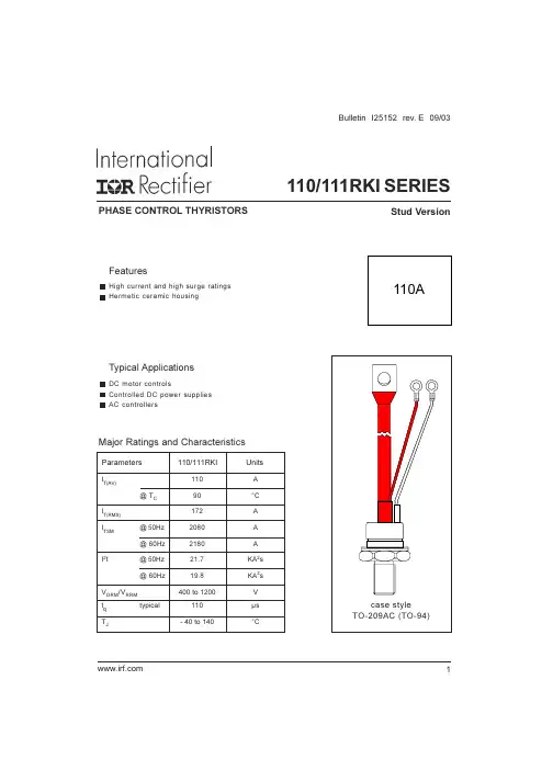
FeaturesHigh current and high surge ratings Hermetic ceramic housingTypical ApplicationsDC motor controlsControlled DC power supplies AC controllersI T(AV)110A @ T C90°C I T(RMS)172A I TSM@ 50Hz 2080A @ 60Hz2180A I 2t@ 50Hz21.7KA 2s @ 60Hz19.8KA 2s VDRM /V RRM 400 to 1200V t q typical110µs T J- 40 to 140°CParameters110/111RKIUnitsMajor Ratings and Characteristics110APHASE CONTROL THYRISTORSStud Version110/111RKI SERIES1Bulletin I25152 rev. E 09/03110/111RKI Series2Bulletin I25152 rev. E 09/03ELECTRICAL SPECIFICATIONS Voltage RatingsVoltageV DRM /V RRM , max. repetitive V RSM , maximum non-I DRM /I RRM max.Type numberCodepeak and off-state voltagerepetitive peak voltage@ T J = T J max.VVmA40400500110/111RKI808009002012012001300I T(AV)Max. average on-state current 110A 180° conduction, half sine wave@ Case temperature90°CI T(RMS)Max. RMS on-state current 172DC @ 83°C case temperature I TSMMax. peak, one-cycle 2080t = 10ms No voltage non-repetitive surge current2180At = 8.3ms reapplied 1750t = 10ms 100% V RRM 1830t = 8.3ms reapplied Sinusoidal half wave,I 2t Maximum I 2t for fusing21.7t = 10msNo voltage Initial T J = T J max.19.8t = 8.3ms reapplied 15.3t = 10ms 100% V RRM 14.0t = 8.3msreappliedI 2√t Maximum I 2√t for fusing 217KA 2√st = 0.1 to 10ms, no voltage reapplied V T(TO)1Low level value of thresholdvoltageV T(TO)2High level value of thresholdvoltager t1Low level value of on-state slope resistancer t2High level value of on-state slope resistance V TM Max. on-state voltage 1.57V I pk = 350A, T J = T J max., t p = 10ms sine pulse I H Maximum holding current 200I LTypical latching current4000.82(16.7% x π x I T(AV) < I < π x I T(AV)), T J = T J max.2.16(16.7% x π x I T(AV) < I < π x I T(AV)), T J = T J max.1.70(I > π x I T(AV)),T J = T J max.Parameter110/111RKIUnits Conditions1.02(I > π x I T(AV)),T J = T J max.On-state ConductionKA 2sVm ΩmAT J = 25°C, anode supply 6V resistive loaddi/dtMax. non-repetitive rate of rise Gate drive 20V, 20Ω, t r ≤ 1µsof turned-on currentT J = T J max, anode voltage ≤ 80% V DRM Gate current 1A, di g /dt = 1A/µsV d = 0.67% V DRM , T J = 25°CI TM= 50A, T J = T J max., di/dt = -5A/µs, V R = 50V dv/dt = 20V/µs, Gate 0V 25ΩParameter110/111RKIUnits Conditionst d Typical delay time 1Switchingt qTypical turn-off time110µs300A/µs110/111RKI Series3Bulletin I25152 rev. E 09/03dv/dt Maximum critical rate of rise of off-state voltageI RRM Max. peak reverse and off-state I DRMleakage currentBlocking500V/µs T J = T J max. linear to 80% rated V DRM Parameter110/111RKIUnits Conditions20mAT J = T J max, rated V DRM /V RRM appliedP GM Maximum peak gate power12T J = T J max, t p ≤ 5msP G(AV)Maximum average gate power3.0T J = T J max, f = 50Hz, d% = 50I GM Max. peak positive gate current 3.0AT J = T J max, t p ≤ 5ms+V GM Maximum peak positive gate voltage-V GMMaximum peak negative gate voltageI GTDC gate current required T J = - 40°C to triggermAT J = 25°C T J = 140°C V GTDC gate voltage required T J = - 40°C to triggerV T J = 25°C T J = 140°C I GD DC gate current not to trigger 6.0mA Parameter110/111RKIUnits Conditions2010TriggeringT J = T J maxTYP.MAX.180-8012040-2.5-1.621-Max. gate current/ voltage not to trigger is the max. value which will not trigger any unit with rated V DRM anode-to-cathode applied Max. required gate trigger/ cur-rent/ voltage are the lowest value which will trigger all units 12V anode-to-cathode appliedW VT J = T J max, t p ≤ 5msT J Max. operating temperature range -40 to 140T stg Max. storage temperature range -40 to 150R thJC Max. thermal resistance,junction to case R thCS Max. thermal resistance,case to heatsink TMounting torque, ± 10%15.5Non lubricated threads(137)14Lubricated threads(120)wt Approximate weight 130gParameter110/111RKIUnits Conditions0.27DC operation0.1Mounting surface, smooth, flat and greased Thermal and Mechanical Specification°CK/WNm(lbf-in)Case styleTO - 209AC (TO-94)See Outline TableV GDDC gate voltage not to trigger0.25V110/111RKI Series 4110/111RKI Series5110/111RKI Series 6110/111RKI Series7110/111RKI Series8Bulletin I25152 rev. E 09/03IR WORLD HEADQUARTERS: 233 Kansas St., El Segundo, California 90245, USA Tel: (310) 252-7105TAC Fax: (310) 252-7309Visit us at for sales contact information. 03/03Data and specifications subject to change without notice.This product has been designed and qualified for Industrial Level.Qualification Standards can be found on IR's Web site.。
NEC Express5800 T110i系列服务器配置指南说明书
NEC Express5800/T110iSystem Configuration GuideIntroductionThis document contains product and configuration information that will enable you to configure your system. The guide will ensure fast and proper configuration of your NEC Express5800 server.March 28, 2019Revision 10.0NEC CorporationContentsTECHNICAL SPECIFICATION (3)Specification (3)EXTERNAL VIEWS (6)Front View (6)Rear Views (7)Dimensions (mm) (8)CONFIGURATION DIAGRAM (10)Expansion Slots (10)SERVER CONFIGURATION (11)1Base Models (11)2Processor (11)3Memory (11)4Internal Hard Disk Drives (13)4.1RAID Configuration (13)4.2Required Components for RAID Configuration (17)4.3Supported Drives (27)5Optical Drive (31)6Flash FDD (31)7Internal RDX / LTO Drives (32)7.1RDX/LTO Drive Selection (32)7.2RDX/LTO Configuration (32)8PCI Card (33)8.1Network Interface Controller (33)8.2SAS Controller (34)8.3Graphics Accelerator (34)8.4Serial Port Adapter (34)9Other Add-in Components (35)9.1Fan Kit (35)9.2Trusted Platform Module Kit (35)9.3Internal Flash Memory (35)9.4High Temperature Support Option (35)9.5Input Devices (35)10Add-on Components (37)10.1Server Management License (37)10.2Dust Proof Kit (37)10.3Rack Conversion Kit (37)10.4Medium and Cartridge (37)REFERENCES (38)Boot Mode Setting (38)Server Management (39)OS Support Matrix for PCI Cards and Embedded Controllers (40)Supported PCI cards and Installable Slots (40)Copyright Notice and Liability Disclaimer (44)REVISION HISTORY (45)Technical Specification Specification(1 / 2)Processor Type Intel®Celeron®processorG3930 Intel®Pentium®processorG4560Intel® Core™i3-7300processorIntel® Xeon®processorE3-1220 v6Clock speed 2.90 GHz 3.50 GHz 4 GHz 3 GHzNumber of Processors 1Cache 2 MB 3 MB 4 MB 8 MBCores and Threads 2C / 2T 2C / 4T 4C / 4T Chipset Intel® C236 ChipsetMemory Type DDR4-2400 ECC Unbuffered DIMMStandard Capacity 0 GBMaximum Capacity 64 GB (4 x 16 GB)Internal Storage Standard Capacity 0 GBMaximum Capacity 48 TB (4 x 12 TB)Disk Controller SATA : 6 Gb/s (Integrated)SATA/SAS : 6/12 Gb/s (Optional)RAID SATA : RAID 0/1/10 (Standard 1 )SATA/SAS : RAID 0/1/5/6/10/50/60 (Optional)Hot Plug Supported with hot plug drive bayOptical Disk Drive Optional5-inch Media Bays 2Disk Drive Bays Hot plug 2.5-inch drive configuration: 8Hot plug 3.5-inch drive configuration: 4Non-hot plug 3.5-inch drive configuration: 4Expansion Slots Total: 4 slots available1 PCIe 3.0 x16 (x16 connector)1 PCIe 3.0 x4 (x8 connector)1 PCIe 3.0 x2 (x8 connector)1 PCIe 3.0 x1 (x8 connector)Video Controller (VRAM) Integrated in Server Management Controller (32MB)Resolution / Color 1600 x 1200 / 16.7M 2Interfaces 1 VGA (15-pin mini D-sub,1 rear)1 to2 Serial (9-pin mini D-sub, RS232-C, 1 to 2 rear)6 USB 3.0 (2 front, 4 rear) (plus 1 internal USB 3.0)2 1000BASE-T LAN connector (RJ-45, 2 rear)1 1000BASE-T LAN connector for Management (RJ-45, 1 rear) Server Management EXPRESSSCOPE Engine 3System Fan StandardPower Supply 1 x 500 Watt 80 non-hot plug PSU2 x 460 Watt 80 PLUS® Platinum certified Hot plug PSU100-240 VAC ± 10% 50 / 60 Hz ± 3 HzPower Consumption (Max. Config, Idling) 132 VA /131 Watt133 VA /132 Watt136 VA /135 Watt133 VA /132 Watt (Max. Config, Operating) 244 VA /242 Watt252 VA /250 Watt257 VA /255 Watt256 VA /254 WattAcoustic Noise (Sound Pressure Level) 3Minimum Config. 28.3 dB Maximum Config. 29.7 dBDimensions (W x D x H ) Standard Bezel: 175.0 x 469.3 x 367.0mm / 6.8 x 18.5 x 14.4 inDust Proof Bezel: 175.0 x 492.0 x 367 mm / 6.8 x 19.3 x 14.4 in Weight (Minimum / Maximum) 11 kg / 18.5 kg, 24.25 lbs. / 40.78 lbs.Temperature, Relative Humidity (non-condensing) Operating: 5° to 40° C / 41° to 104° F (Standard)or 5° to 48° C / 41° to 118° F (Optional), 10 to 85%Non-Operating: -10° to 55° C / 14° to 131° F, 10 to 85% Regulatory and Safety FCC, c-UL, CE, CB, RoHS, BSMI, CCCMicrosoft® Windows Server® 2012 DatacenterMicrosoft® Windows Server® 2012 R2 StandardMicrosoft® Windows Server® 2012 R2 DatacenterMicrosoft® Windows Server® 2016 StandardMicrosoft® Windows Server® 2016 DatacenterRed Hat Enterprise Linux 7.3 or later 4 6VMware ESXi 6.0 Update 3 5VMware ESXi 6.5 5VMware ESXi 6.7 51 Embedded SATA RAID controller is supported only on limited OS.2 Maximum resolution available via EXPRESSSCOPE Engine3 remote console is 1280 x 1024 / 65K colors.3 Noise emission was measured in accordance with ISO 7779, at 25°C. The actual value may vary by the operating environment.4 For Linux support, contact your sales representative or visit the NEC website at:/global/prod/express/linux/index.html5 VMware ESXi is supported only on Xeon processor systems.(2 / 2)Processor Type Intel® Xeon®processorE3-1225 v6 Intel® Xeon®processorE3-1230 v6Intel® Xeon®processorE3-1270 v6Clock speed 3.30 GHz 3.50 GHz 3.80GHzNumber of Processors 1Cache 8 MBCores and Threads 4C / 4T 4C / 8TChipset Intel® C236 ChipsetMemory Type DDR4-2400 ECC Unbuffered DIMMStandard Capacity 0 GBMaximum Capacity 64 GB (4 x 16 GB)Internal Storage Standard Capacity 0 GBMaximum Capacity 48 TB (4 x 12 TB)Disk Controller SATA : 6 Gb/s (Integrated)SATA/SAS : 6/12 Gb/s (Optional)RAID SATA : RAID 0/1/10 (Standard 1 )SATA/SAS : RAID 0/1/5/6/10/50/60 (Optional)Hot Plug Supported with hot plug drive bayOptical Disk Drive Optional5-inch Media Bays 2Disk Drive Bays Hot plug 2.5-inch drive configuration: 8Hot plug 3.5-inch drive configuration: 4Non-hot plug 3.5-inch drive configuration: 4Expansion Slots Total: 4 slots available1 PCIe 3.0 x16 (x16 connector)1 PCIe 3.0 x4 (x8 connector)1 PCIe 3.0 x2 (x8 connector)1 PCIe 3.0 x1 (x8 connector)Video Controller (VRAM) Integrated in Server Management Controller (32MB)Resolution / Color 1600 x 1200 / 16.7M 2Interfaces 1 VGA (15-pin mini D-sub,1 rear)1 to2 Serial (9-pin mini D-sub, RS232-C, 1 to 2 rear)6 USB 3.0 (2 front, 4 rear) (plus 1 internal USB 3.0)2 1000BASE-T LAN connector (RJ-45, 2 rear)1 1000BASE-T LAN connector for Management (RJ-45, 1 rear) Server Management EXPRESSSCOPE Engine 3System Fan StandardPower Supply 1 x 500 Watt 80 non-hot plug PSU2 x 460 Watt 80 PLUS® Platinum certified Hot plug PSU100-240 VAC ± 10% 50 / 60 Hz ± 3 HzConsumption 133 Watt 134 Watt 133 Watt(Max. Config, Operating) 264 VA /262 Watt 288 VA /286 Watt290 VA /288 WattAcoustic Noise (Sound Pressure Level) 3Minimum Config. 28.3 dB Maximum Config. 29.7 dBDimensions (W x D x H ) Standard Bezel: 175.0 x 469.3 x 367.0mm / 6.8 x 18.5 x 14.4 inDust Proof Bezel: 175.0 x 492.0 x 367 mm / 6.8 x 19.3 x 14.4 inWeight (Minimum / Maximum) 11 kg / 18.5 kg, 24.25 lbs. / 40.78 lbs.Temperature, Relative Humidity (non-condensing) Operating: 5° to 40° C / 41° to 104° F (Standard)or 5° to 48° C / 41° to 118° F (Optional), 10 to 85%Non-Operating: -10° to 55° C / 14° to 131° F, 10 to 85%Regulatory and Safety FCC, c-UL, CE, CB, RoHS, BSMI, CCCOperating Systems and Virtualization Software Microsoft® Windows Server® 2012 StandardMicrosoft® Windows Server® 2012 DatacenterMicrosoft® Windows Server® 2012 R2 StandardMicrosoft® Windows Server® 2012 R2 DatacenterMicrosoft® Windows Server® 2016 StandardMicrosoft® Windows Server® 2016 DatacenterRed Hat Enterprise Linux 7.3 or later 4 6VMware ESXi 6.0 Update 3 5VMware ESXi 6.5 5VMware ESXi 6.7 51 Embedded SATA RAID controller is supported only on limited OS.2 Maximum resolution available via EXPRESSSCOPE Engine3 remote console is 1280 x 1024 / 65K colors.3 Noise emission was measured in accordance with ISO 7779, at 25°C. The actual value may vary by the operating environment.4 For Linux support, contact your sales representative or visit the NEC website at:/global/prod/express/linux/index.html5 VMware ESXi is supported only on Xeon processor systems.External ViewsFront ViewWith Front bezelHot Plug 2.5-inch Drive ConfigurationHot Plug 3.5-inch Drive ConfigurationNon-hot Plug 3.5-inch Drive ConfigurationB. Dump (NMI) Button K. Drive Bay CoverC. BMC Reset Button L. Cover KeyD. Power LEDM. StabilizerE. Power Capping LED N. 5.25-inch Media Bay 1F. System Status LED 1 O. 5.25-inch Media Bay 2G. System Status LED 2 P. Optical Disk DriveH. Global LED 1 Q. 2.5-inch Drive BayI.Global LED 2R.3.5-inch Drive BayA G E C KJ LIB D F H MPO NQRPO N RPO NRear ViewsHot Plug Power Supply ConfigurationNon-hot Plug Power Supply ConfigurationB. VGA Connector F. PCI SlotsC. USB ConnectorsG. AC InletD.Management LAN ConnectorH.Power Supply UnitDCBAGEFDimensions (mm)Standard BezelNon-redundant Power ConfigurationRedundant Power Configuration469.3175.0367.0249.0498.4Dust Proof BezelNon-redundant Power ConfigurationRedundant Power Configuration518.2492.0367.0175.0249.0492.0 175.0249.0506.492.367.0Configuration DiagramLegend: Standard components Mandatory components Expansion Slots#2 PCIe 3.0 x1, x8 connector, Full Height, up to 173mm length#3 PCIe 3.0 x16, x16 connector, Full Height, up to 312mm length#4 PCIe 3.0 x4, x8 connector, Full Height, up to 173mm lengthServer Configuration1Base Modelsno CPU, no RAM, no Drive Cage, no HDD, no Optiocal Drive, no Keyboard, no Mouse Including:1x 500 Watt non-hot plug power supplyNEC Express5800/T110ino CPU, no RAM, no Drive Cage, no HDD, no Optiocal Drive, no Keyboard, no Mouse Including:2x 460 Watt hot plug power supply N8100-2534FNOTE:● The base model must be ordered with a processor kit, memory, a drive cage, and an optical drive. ● Keyboard and mouse are not included in the base models. Please order separately if necessary.2 ProcessorAvailable sockets: 1RequiredIntel® Celeron ® Processor G3930 (2.9 GHz, 2C/2T, 2 MB) Pentium G4560 Processor KitIntel® Pentium ® Processor G4560 (3.5 GHz, 2C/4T, 3 MB) N8101-1086F Core i3-7300 Processor KitIntel® Core ™ i3-7300 Processor (4 GHz, 2C/4T, 4 MB) N8101-1087F Xeon E3-1220 v6 Processor KitIntel® Xeon ® Processor E3-1220 v6 (3.0 GHz, 4C/4T, 8 MB) N8101-1091F Xeon E3-1225 v6 Processor KitIntel® Xeon ® Processor E3-1225 v6 (3.3 GHz, 4C/4T, 8 MB) N8101-1090F Xeon E3-1230 v6 Processor KitIntel® Xeon ® Processor E3-1230 v6 (3.5 GHz, 4C/8T, 8 MB) N8101-1089F Xeon E3-1270 v6 Processor KitIntel® Xeon ® Processor E3-1270 v6 (3.8 GHz, 4C/8T, 8 MB)N8101-1088FNOTE:● One processor kit from above must be installed.● VMware ESXi is not supported on Celeron processor systems, Pentium processor or Core i3 processor systems.3 MemoryAvailable slots: 48GB Unbuffered ECC DIMM, DDR4-2400 16GB DDR4-2400 UNB Memory Kit16GB Unbuffered ECC DIMM, DDR4-2400 N8102-702FNOTE:● Minimum one memory kit must be installed.● It is recommended to install memory kits in pairs of two identical DIMMs for dual-channel symmetric memory configurations toincrease memory transfer speed.● At least 5 GB of memory is required for VMware ESXi™ 6.0, and VMware ESXi™ 6.5.Maximum Available MemorySee the table below for the maximum memory size that you can actually use on your system.Microsoft Windows Server 2012 DatacenterMicrosoft Windows Server 2012 R2 StandardMicrosoft Windows Server 2012 R2 Datacenter24TB 164GB Microsoft Windows Server 2016 StandardMicrosoft Windows Server 2016 DatacenterRed Hat Enterprise Linux 7 6 TB 64 GB VMware ESXi 6.0 6 TB 264 GB VMware ESXi 6.5 12TB 364 GB VMware ESXi 6.7 316TB 64 GB 1 The maximum available memory size of Hyper-V systems are below:Windows Server 2012 and Windows Server 2012 R2 : 4 TBWindows Server 2016 : 24 TB2 Up to 4 TB of main memory is available to each virtual machine.3 Up to 6 TB of main memory is available to each virtual machine.4Internal Hard Disk Drives4.1RAID ConfigurationRefer to the section in accordance with your disk form factor and RAID configuration4.1.12.5-inch DriveRAID 0/1/10 No Cache 4.2.4 4.3.3 Windows Server 2012 Windows Server 2012 R2 Windows Server 2016Non-RAID (Embedded SATA)4.2.1 4.3.1 RAID 0/1 (Embedded SATA RAID) 4.2.2 4.3.2 RAID 0/1/10 No Cache 4.2.4 4.3.4RAID 0/1/10 2GB Cache 4.2.6 RAID 5/6/50/60 2GB Cache 4.2.9 RAID 5/6/50/60 4GB Cache 4.2.10Red Hat Enterprise Linux 7Non-RAID (Embedded SATA) 4.2.1 4.3.1 RAID 0/1/10 No Cache 4.2.3 4.3.4RAID 0/1/10 1GB Cache 4.2.5 RAID 5/6/50/60 1GB Cache 4.2.7 RAID 5/6/50/60 2GB Cache 4.2.8 VMware ESXi 6.5 VMware ESXi 6.7Non-RAID (Embedded SATA) 4.2.1 4.3.1 RAID 0/1/10 No Cache 4.2.4 4.3.4RAID 0/1/10 2GB Cache 4.2.6 RAID 5/6/50/60 2GB Cache 4.2.9 RAID 5/6/50/60 4GB Cache4.2.10NOTE:● Up to four drives can be installed when you choose the Embedded SATA Non-RAID controller. ● All drives within a RAID array should be of the same capacity and rotation speed.● Up to two kinds of drives selected from SAS 10K HDDs (512n), SAS 10K HDDs (512e), SAS 15K HDDs, SATA HDDs, SASSSDs, SATA SSDs (ME), and SATA SSDs (VE) can be mixed in a system.● To configure a large-capacity RAID array, it is recommended to configure in RAID 6 or RAID 60 in order to minimize the risk ofbecoming multiple hard drives failure during the RAID rebuilding process.S l o t 1S l o t 3S l o t 2S l o t 4S l o t 5S l o t 7S l o t 6S l o t 04.1.2 Hot plug 3.5-inch DriveWindows Server 2012 Windows Server 2012 R2 Windows Server 2016Non-RAID (Embedded SATA)4.2.11 4.3.5 RAID 0/1 (Embedded SATA RAID) 4.2.12 4.3.6RAID 0/1/10 No Cache 4.2.14 RAID 0/1/10 2GB Cache 4.2.16 RAID 5/6/50/60 2GB Cache 4.2.19 RAID 5/6/50/60 4GB Cache 4.2.20 VMware ESXi 6.5 VMware ESXi 6.7Non-RAID (Embedded SATA) 4.2.11 4.3.5 RAID 0/1/10 No Cache 4.2.14 4.3.6RAID 0/1/10 2GB Cache 4.2.16 RAID 5/6/50/60 2GB Cache 4.2.19 RAID 5/6/50/60 4GB Cache 4.2.20 Red Hat Enterprise Linux 7Non-RAID (Embedded SATA) 4.2.11 4.3.6RAID 0/1/10 No Cache 4.2.13 RAID 0/1/10 1GB Cache 4.2.15 RAID 5/6/50/60 1GB Cache 4.2.17 RAID 5/6/50/60 2GB Cache4.2.18NOTE:All hard drives within a RAID array should be of the same capacity and rotation speed.S l o t 0S l o t 1S l o t 2S l o t 34.1.3 Non-hot plug 3.5-inch DriveWindows Server 2012 Windows Server 2012 R2 Windows Server 2016Non-RAID (Embedded SATA)4.2.21 4.3.7 RAID 0/1 (Embedded SATA RAID) 4.2.22 4.3.8RAID 0/1/10 No Cache 4.2.24 RAID 0/1/10 2GB Cache 4.2.25 RAID 5/6/50/60 2GB Cache 4.2.29 RAID 5/6/50/60 4GB Cache 4.2.30 VMware ESXi 6.5 VMware ESXi 6.7Non-RAID (Embedded SATA) 4.2.21 4.3.7 RAID 0/1/10 No Cache 4.2.24 4.3.8RAID 0/1/10 2GB Cache 4.2.26 RAID 5/6/50/60 2GB Cache 4.2.27 RAID 5/6/50/60 2GB Cache 4.2.29 RAID 5/6/50/60 4GB Cache 4.2.30 Red Hat Enterprise Linux 7Non-RAID (Embedded SATA) 4.2.21 4.3.7 RAID 0/1/10 No Cache 4.2.23 4.3.8RAID 0/1/10 1GB Cache 4.2.25 RAID 5/6/50/60 1GB Cache 4.2.27 RAID 5/6/50/60 2GB Cache4.2.28NOTE:All hard drives within a RAID array should be of the same capacity and rotation speed.4.1.4 M.2 SATA SSDThe M.2 SATA SSD can be used for boot drive only. See the table below for the system configuration of M.2 SATA SSD and support for the mixed installation of M.2 SATA SSDs and internal hard drives.VMware ESXi 6.7 RAID 0/1/10 2GB Cache4.2.35 Windows Server 2012 Windows Server 2012 R2 Windows Server 2016RAID 0/1 (Embedded SATA RAID)4.2.31Supported: Optional RAID controller is required to install internal hard drives. RAID 0/1/10 No Cache 4.2.33 Not supportedRAID 0/1/10 2GB Cache 4.2.35Red Hat Enterprise Linux 7 RAID 0/1/10 No Cache 4.2.32 Not supportedRAID 0/1/10 1GB Cache 4.2.34NOTE:S l o t 0S l o t 1S l o t 2S l o t 3A drive cage kit is required when no internal hard drive is installed.4.2 Required Components for RAID Configuration4.2.1 Embedded SATA Non-RAID Controller for 2.5-inch Drives4 x 6Gb/s SATACable Internal SATA Cable1 x Mini SAS HD to 1 x Mini SAS HD(Attached in Cage)Drive Cage Required 2.5-inch Hot Plug Drive Cage Kit8 x 2.5-inch hot plug hard drive baysN8154-80FNOTE●Hot plug insertion/removal is not supported with the embedded SATA Non-RAID controller.4.2.2 Embedded SATA RAID Controller for 2.5-inch Drives4 x 6Gb/s SATA, RAID0/1/10 capableCable Internal SATA Cable1 x Mini SAS HD to 1 x Mini SAS HD(Attached in Cage)Drive Cage Required 2.5-inch Drive Cage8 x 2.5-inch hot plug drive baysN8154-80FNOTE●All hard drives within a RAID array should be of the same capacity.4.2.3 RAID 0/1 Controller without Cache for 2.5-inch DrivesRequired Broadcom MegaRAID SAS 9341-8iRAID0/1/10, no memory cache, Int. 8, PCIe 3.0(x8), SAS 12Gb/s, SATA6Gb/sCable Internal SATA Cable1 x Mini SAS HD to 1 x Mini SAS HD(Attached in Cage)Internal SAS/SATA Cable1 x Mini SAS HD to 1 x Mini SAS HD, for 5th - 8th hard drivesK410-340(00)Drive Cage Required 2.5-inch Drive Cage8 x 2.5-inch hot plug drive baysN8154-80FNOTE:●All drives within a RAID array should be of the same type, capacity and rotation speed..4.2.4 RAID 0/1 Controller without Cache for 2.5-inch DrivesRequired Avago(LSI) MegaRAID SAS 944N-8iRAID0/1/10, no memory cache, Int. 8, PCIe 3.0(x8), SAS 12Gb/s, SATA6Gb/sCable Internal SATA Cable1 x Mini SAS HD to 1 x Mini SAS HD(Attached in Cage)Internal SAS/SATA Cable1 x Mini SAS HD to 1 x Mini SAS HD, for 5th - 8th hard drivesK410-340(00)Drive Cage Required 2.5-inch Drive Cage8 x 2.5-inch hot plug drive baysN8154-80FNOTE:●All drives within a RAID array should be of the same type, capacity and rotation speed.4.2.5 RAID 0/1 Controller with 1GB Cache for 2.5-inch DrivesRequired Avago(LSI) MegaRAID SAS 9362-8iRAID0/1/10, 1GB, Int. 8, PCIe 3.0(x8), SAS 12Gb/s, SATA 6Gb/sFlash Backup Recommended Flash Buckup Unitfor Avago(LSI) MegaRAID SAS 9362-8i500mm Cable for Flash Backup Unit includedN8103-180Cable Internal SAS/SATA Cable1 x Mini SAS HD to 1 x Mini SAS HD(Attached in Cage)Internal SAS/SATA Cable1 x Mini SAS HD to 1 x Mini SAS HD, for 5th - 8th hard drivesK410-340(00)Drive Cage Required 2.5-inch Drive Cage8 x 2.5-inch hot plug drive baysN8154-80FNOTE:●All drives within a RAID array should be of the same type, capacity and rotation speed.●Up to two kinds of drives selected from SAS 10K HDDs, SAS 15K HDDs, SATA HDDs, SATA SSD and SAS SSDs can bemixed.4.2.6 RAID 0/1 Controller with 2 GB Cache for 2.5-inch DrivesRequired Avago(LSI) MegaRAID SAS 946N-8iRAID 0/1/10, 2GB, Int. 8, PCIe 3.0 x8, SAS 12Gb/s, SATA 6Gb/sRAID Controller (2GB, RAID 0/1, WT)Avago(LSI) MegaRAID SAS 945N-8iRAID 0/1/10, 2GB, Int. 8, PCIe 3.0 x8, SAS 12Gb/s, SATA 6Gb/sN8103-210Flash Backup Recommended Flash Buckup Unitfor Avago(LSI) MegaRAID SAS 946N-8i550mm Cable for Flash Backup Unit includedNOTE:It can not be connected to N8103-210 RAID ControllerN8103-209Cable Internal SAS/SATA Cable1 x Mini SAS HD to 1 x Mini SAS HD(Attached in Cage)Internal SAS/SATA Cable1 x Mini SAS HD to 1 x Mini SAS HD, for 5th - 8th hard drivesK410-340(00)Drive Cage Required 2.5-inch Drive Cage8 x 2.5-inch hot plug drive baysN8154-80FNOTE:●All drives within a RAID array should be of the same type, capacity and rotation speed.●Up to two kinds of drives selected from SAS 10K HDDs, SAS 15K HDDs, SATA HDDs, SATA SSD and SAS SSDs can bemixed.●SSDs (VE) can be mixed in a system.4.2.7 RAID 5/6 Controller with 1 GB Cache for 2.5-inch DrivesRequired Avago(LSI) MegaRAID SAS 9362-8iRAID0/1/5/6/10/50/60, 1GB, Int. 8, PCIe 3.0(x8), SAS 12Gb/s, SATA6Gb/sFlash Backup Recommended Flash Buckup Unitfor Avago(LSI) MegaRAID SAS 9362-8i500mm Cable for Flash Backup Unit includedN8103-180Cable Internal SAS/SATA Cable1 x Mini SAS HD to 1 x Mini SAS HD(Attached in Cage)Internal SAS/SATA Cable1 x Mini SAS HD to 1 x Mini SAS HD, for 5th - 8th hard drivesK410-340(00)Drive Cage Required 2.5-inch Drive Cage8 x 2.5-inch hot plug drive baysN8154-80FNOTE:●All drives within a RAID array should be of the same type, capacity and rotation speed.●Up to two kinds of drives selected from SAS 10K HDDs, SAS 15K HDDs, SATA HDDs, SATA SSD and SAS SSDs can bemixed.4.2.8 RAID 5/6 Controller with 2 GB Cache for 2.5-inch DrivesRequired Broadcom MegaRAID SAS 9362-8iRAID0/1/5/6/10/50/60, 2 GB, Int. 8, PCIe 3.0(x8), SAS 12Gb/s, SATA6Gb/sFlash Backup Recommended Flash Backup Unitfor Broadcom MegaRAID SAS 9362-8i500mm Cable for Flash Backup Unit includedN8103-180Cable Internal SAS/SATA Cable1 x Mini SAS HD to 1 x Mini SAS HD(Attached in Cage)Internal SAS/SATA Cable1 x Mini SAS HD to 1 x Mini SAS HD, for 5th - 8th hard drivesK410-340(00)Drive Cage Required 2.5-inch Drive Cage8 x 2.5-inch hot plug drive baysN8154-80FNOTE:●All drives within a RAID array should be of the same type, capacity and rotation speed.●Up to two kinds of drives selected from SAS 10K HDDs, SAS 15K HDDs, SATA HDDs, SAS SSDs, SATA SSDs (ME), and SATASSDs (VE) can be mixed in a system.4.2.9 RAID 5/6 Controller with 2 GB Cache for 2.5-inch DrivesRequired Avago(LSI) MegaRAID SAS 946N-8iRAID0/1/5/6/10/50/60, 2GB, Int. 8, PCIe 3.0 x8, SAS 12Gb/s, SATA6Gb/sRAID Controller (2GB, RAID 0/1/5/6, WT)Avago(LSI) MegaRAID SAS 945N-8iRAID0/1/5/6/10/50/60, 2GB, Int. 8, PCIe 3.0 x8, SAS 12Gb/s, SATA6Gb/sN8103-211Flash Backup Recommended Flash Backup Unitfor Avago(LSI) MegaRAID SAS 946N-8i550mm Cable for Flash Backup Unit includedNOTE:It can not be connected to N8103-211 RAID ControllerN8103-209Cable Internal SAS/SATA Cable1 x Mini SAS HD to 1 x Mini SAS HD(Attached in Cage)Internal SAS/SATA Cable1 x Mini SAS HD to 1 x Mini SAS HD, for 5th - 8th hard drivesK410-340(00)Drive Cage Required 2.5-inch Drive Cage8 x 2.5-inch hot plug drive baysN8154-80FNOTE:●All drives within a RAID array should be of the same type, capacity and rotation speed.●Up to two kinds of drives selected from SAS 10K HDDs, SAS 15K HDDs, SATA HDDs, SATA SSD and SAS SSDs can bemixed.4.2.10 RAID 5/6 Controller with 4 GB Cache for 2.5-inch DrivesRequired Avago(LSI) MegaRAID SAS 946N-8iRAID0/1/5/6/10/50/60, 4GB, Int. 8, PCIe 3.0(x8), SAS 12Gb/s, SATA6Gb/sFlash Backup Recommended Flash Buckup Unitfor Avago(LSI) MegaRAID SAS 946N-8i550mm Cable for Flash Backup Unit includedN8103-209Cable Internal SAS/SATA Cable1 x Mini SAS HD to 1 x Mini SAS HD(Attached in Cage)Internal SAS/SATA Cable1 x Mini SAS HD to 1 x Mini SAS HD, for 5th - 8th hard drivesK410-340(00)Drive Cage Required 2.5-inch Drive Cage8 x 2.5-inch hot plug drive baysN8154-80FNOTE:●All drives within a RAID array should be of the same type, capacity and rotation speed.4.2.11 Embedded SATA Non-RAID Controller for 3.5-inch Drives4 x 6Gb/s SATACable Internal SAS/SATA Cable1 x Mini SAS HD to 1 x Mini SAS HD(Attached in Cage)Drive Cage Required 3.5-inch Drive Cage4 x 3.5-inch hot plug drive baysN8154-79FNOTE●Hot plug insertion/removal is not supported with the embedded SATA Non-RAID controller.4.2.12 Embedded SATA RAID Controller for 3.5-inch Drives4 x 6Gb/s SATA, RAID0/1/10 capableCable Internal SAS/SATA Cable1 x Mini SAS HD to 1 x Mini SAS HD(Attached in Cage)Drive Cage Required 3.5-inch Drive Cage4 x 3.5-inch hot plug drive baysN8154-79FNOTE:●All hard drives within a RAID array should be of the same capacity.●Embedded SATA RAID Controller does not support RAID 10 configured with 2TB or more HDDs.4.2.13 RAID 0/1 Controller without Cache for 3.5-inch DrivesRequired Broadcom MegaRAID SAS 9341-8iRAID0/1/10, no memory cache, Int. 8, PCIe 3.0(x8), SAS 12Gb/s, SATA6Gb/sCable Internal SAS/SATA Cable1 x Mini SAS HD to 1 x Mini SAS HD(Attached in Cage)Drive Cage Required 3.5-inch Drive Cage4 x 3.5-inch hot plug drive baysN8154-79FNOTE:●All hard drives within a RAID array should be of the same capacity.4.2.14 RAID 0/1 Controller without Cache for 3.5-inch DrivesRequired Avago(LSI) MegaRAID SAS 944N-8iRAID0/1/10, no memory cache, Int. 8, PCIe 3.0(x8), SAS 12Gb/s, SATA6Gb/sCable Internal SAS/SATA Cable1 x Mini SAS HD to 1 x Mini SAS HD(Attached in Cage)Drive Cage Required 3.5-inch Drive Cage4 x 3.5-inch hot plug drive baysN8154-79FNOTE:●All hard drives within a RAID array should be of the same capacity.4.2.15 RAID 0/1 Controller with 1 GB Cache for 3.5-inch DrivesRequired Avago(LSI) MegaRAID SAS 9362-8iRAID0/1/10, 1GB, Int. 8, PCIe 3.0(x8), SAS 12Gb/s, SATA 6Gb/sFlash Backup Recommended Flash Buckup Unitfor Avago(LSI) MegaRAID SAS 9362-8i500mm Cable for Flash Backup Unit includedN8103-180Cable Internal SAS/SATA Cable1 x Mini SAS HD to 1 x Mini SAS HD(Attached in Cage)Drive Cage Required 3.5-inch Drive Cage4 x 3.5-inch hot plug drive baysN8154-79FNOTE:●All hard drives within a RAID array should be of the same capacity.4.2.16 RAID 0/1 Controller with 2 GB Cache for 3.5-inch DrivesRequired Avago(LSI) MegaRAID SAS 946N-8iRAID0/1/10, 2GB, Int. 8, PCIe 3.0(x8), SAS 12Gb/s, SATA 6Gb/sRAID Controller (2GB, RAID 0/1, WT)Avago(LSI) MegaRAID SAS 945N-8iRAID 0/1/10, 2GB, Int. 8, PCIe 3.0 x8, SAS 12Gb/s, SATA 6Gb/sN8103-210Flash Backup Recommended Flash Buckup Unitfor Avago(LSI) MegaRAID SAS 946N-8i550mm Cable for Flash Backup Unit includedNOTE:It can not be connected to N8103-210 RAID ControllerN8103-209Cable Internal SAS/SATA Cable1 x Mini SAS HD to 1 x Mini SAS HD(Attached in Cage)Drive Cage Required 3.5-inch Drive Cage4 x 3.5-inch hot plug drive baysN8154-79FNOTE:●All hard drives within a RAID array should be of the same capacity.4.2.17 RAID 5/6 Controller with 1 GB Cache for 3.5-inch DrivesRequired Avago(LSI) MegaRAID SAS 9362-8iRAID0/1/5/6/10/50/60, 1GB, Int. 8, PCIe 3.0(x8), SAS 12Gb/s, SATA6Gb/sFlash Backup Recommended Flash Buckup Unitfor Avago(LSI) MegaRAID SAS 9362-8i500mm Cable for Flash Backup Unit includedN8103-180Cable Internal SAS/SATA Cable1 x Mini SAS HD to 1 x Mini SAS HD(Attached in Cage)Drive Cage Required 3.5-inch Drive Cage4 x 3.5-inch hot plug drive baysN8154-79F4.2.18 RAID 5/6 Controller with 2 GB Cache for 3.5-inch Drives。
CASIO PX-110电子琴 说明书
錄製您的鍵盤彈奏 ........................... E-17 自歌曲儲存器重播 ........................... E-18 刪除歌曲儲存器數據 ....................... E-19
其他設定......................................... E-20
電子琴放置位置................................ E-25 電子琴保養........................................ E-25 鋰電池................................................ E-25
設定控制鍵圖表............................. E-26 附錄................................................... A-1
音色一覽表..........................................A-1 節奏一覽表..........................................A-1 歌曲一覽表..........................................A-1 指法和弦圖..........................................A-2
請向電氣技師諮詢更換不適合的插座孔。
10. 保護電源線不被踩到或夾到,特別是插頭、便利插座及設備出線口等處。
11. 僅使用製造商所指定之附件/配件。
12. 僅於製造商所指定或與設備一起販售之手推車、架子、三腳架、托架或桌子上使用。當使用手推車移動手推車/設
依玛斯激光打码机操作手册 6
SL076016che 6/08 iiiMarkem—Imaje SmartLase® 110i 操作指南鸣谢SmartLase® SL110i 操作指南是在以下地点编写的:Markem-Imaje150 Congress StreetKeene, NH 03431 USA商标Markem 是Markem Corporation 的注册商标。
免责声明据我们所知,本指南所含信息在印刷时均正确无误。
但是,秉承我们不断提升品质的策略,会对这些信息进行修改。
本指南版本代表销售时的设计,也许并不代表最新的软件设计。
版权所有® 2008 保留所有权利。
目录SL076016che 6/08 v第1 章一般信息1 欢迎使用SmartLase®110i . . 。
. 。
. 。
. 。
. . 。
. . 。
. 。
. 。
. 。
. 。
. 。
. 。
1-11。
1 本指南所含内容。
. 。
. 。
. . . . 。
. 。
. 。
. 。
. . . 。
. . 。
. . 。
. 。
. . 。
. . . . 1—11。
2 联系Markem—Imaje 。
. 。
. 。
. . 。
. 。
. . . . 。
. . . 。
. 。
. . . 。
. 。
. 。
. . . . 。
. . 。
1—11.3 相关文档. 。
. 。
. . . 。
. . . 。
. . 。
. . 。
. 。
. . 。
. 。
. . 。
. . . 。
. . 。
. . 。
1-12 开始前。
. . 。
. . 。
. 。
. . . . 。
. 。
. 。
. . . 。
. . 。
. 。
. . 。
. . 。
. 。
. 。
. 。
. 。
. . 。
1-23 词汇表。
. . . . . . 。
. . . 。
. . 。
. 。
. 。
. 。
. 。
. 。
. 。
. . 。
. 。
. 。
. . 。
. . 。
. 1—34 规格。
. . . . . . 。
. . . . 。
. . 。
. . . . . . 。
SINAMICS G110操作手册
警告
本设备带有危险电压,而且它所控制的是带有危险电压的转动机件。如果不遵守“警告”的规 定,或不按本手册的要求进行操作,就可能会造成死亡,严重的人身伤害或重大的财产损失。 只有经过认证合格的专业人员才允许操作本设备,并且在使用设备之前要熟悉本手册中所有的 安全说明和有关安装,操作和维护的规定。正确地进行搬运装卸,就位安装和操作维护,是实 现本设备安全和成功地投入运行的可靠保证。 注意触电的危险。即使电源已经切断,SINAMICS G110变频器的直流回路(DC-Link)电容器上 仍然带有危险电压。因此,在电源关断 5 分钟以后才允许打开本设备,并在设备的任何部件上 进行工作。在这段时间里,变频器内部电容器将放电完毕。 即使变频器处于不工作状态,其电源输入端子,直流回路和电动机接线端子仍可能带有危险电 压。因此,在电源关断 5 分钟以后,等待电容器放电完毕才允许在本设备上开展安装工作。 在利用软件调试工具 STARTER 或从 BOP 向变频器下载参数时,数字输出可能产生虚假信号。 因此,在对变频器采取相应的措施,以便完成参数下载之前,必须确信,任何悬挂性质的负载 都应是安全的,例如,利用外部制动装置加以紧固,或者把负载降低到接近地面的安全高度。
警告,注意和说明
以下的“警告”,“注意”和“说明”是为了您的安全而提出的,是防止设备或与其连接的机械 部件受到损伤而采取的一些措施。 特殊的“警告”,“注意”和“说明”:适用于特殊的操作,放在有关章节的开头,并在该章节 需要的地方再加以重复或补充。 请仔细阅读这些“警告”,“注意”和“说明”,因为它们为您提供了人身安全的保障,并且有 助于延长 SINAMICS G110 变频器以及与之连接的设备的使用寿命。
电气安装 ............................................................................................................................... 2-1