FreeForm软件教程-V10新增功能详解
simufact.Forming10.0新功能介绍
S i m u f a c t .f o r m i n g 10.0simufact.forming 10.0u总览u改进前处理功能u 新功能菜单u 更加灵活的定义u改进后处理功能u改进并行计算能力u改进模具应力分析功能u改进钣金成形模块u改进机构运动模块u 环轧设备运动u 开坯锻设备运动u改进网格划分功能uGP-GUI 界面u 帮助u 改进实例分析u 新用户帮助手册S i m u f a c t .f o r m i n g 10.0总览S i m u f a c t .f o r m i n g 10.0General remarksu Simufact.forming 10.0 基于§MSC 软件Marc2010和Dytran2010 §Windows 界面支持更多功能§GP-GUI 基于Mentat2010§CAD 导入基于CADfix-Version 8.0 ServicePack 1支持最新的CAD 软件版本§全新的图形界面§新的安装和文件结构§Windows 32bit and 64bit (XP , Windows 7)Linux64 (no Forming-GUI)S i m u f a c t .f o r m i n g 10.0Installationu 所有的设定都储存在一个INI 文件~USER/ AppData\Roaming\Simufact /simufact.forming_10.0.ini ØWill allow to copy the installation to other computerØUsers can use the same settingsØThe INI-file will be written when you start the first time the GUI u Ini-File can directly be copied for other users u Whole installation can be copied or mirrored without a new setupon other computersS i m u f a c t .f o r m i n g 10.0Default Unit-Systemu Default UNIT-System after the installation is Si-mm-UnitAll examples are based on this systemUnit-System can be reset by usingS i m u f a c t.f o r m i n g 10.0u Add stl-Import for CAD Preview/Import with CAD-repair functionalitybased on CADFixu Latest Version from CADFix 8.0 Service Pack1 are implemented CADFix InterfaceIntelligent model quality diagnostics and repair Automatical defeaturingAutomaticalrepair Support Assemblies Native Interfaces CA TIA V5/R20CA TIA V4/ 4.1.X, 4.2.X Pro/Engineer Wildfire 4SolidWorks 2009Unigraphics NX7Inventor 2010Neutral Interfaces ACIS R20IGES 5.3STEP AP203 & AP214Parasolid V22VDASF 2.0STLS i m u f a c t .f o r m i n g 10.0Improved View CapabilitiesS i m u f a c t .f o r m i n g 10.0u Improved predefined view concept u 3 different View and Zoom settings can be stored 1.Global for all GUI ’s which are opened from the user 2.Stored for the current project 3.Stored for each processàThis option allows to define more flexible the view and zoomfactor for a more easy post processing and for variationsS i m u f a c t .f o r m i n g 10.0u New global setting for edge angle for outline view Edge angle = 5 deg Edge angle = 30 degS i m u f a c t .f o r m i n g 10.0u New option to control Cache for Graphicusupport huge models u Reduce out-of-memory problemsOFF : All results will not hold in the memory ON : All results are hold in th memory.Current:current used memory Clear: Clear all result information in memory Clear cache between animation steps:Results are removed from memory after each animation stepSimufact.forming1.u New option to activate filters in process and inventory windowu This allows the user to show or hide objects andprocesses very easy and concentrate on the things he want to do§eg. hide all used geometriesS i m u f a c t .f o r m i n g 10.0u Define number of entries for the “open project list ” (default: 4)S i m u f a c t .f o r m i n g 10.0uNew Cutting function with u There is a new option to decided which part should be cut 1.All components (default)2.All except workpiece 3.Only workpieceS i m u f a c t .f o r m i n g 10.0Improved Preprocessing CapabilitiesS i m u f a c t .f o r m i n g 10.0uStore comment for the projectS i m u f a c t .f o r m i n g 10.0uImproved support for default settings for process types uSettings are stored in ~InstallDir/sfForming/setting/processtype.ini u Following parameters can be predefined by the user§Default Solver and dimension, cold/or hot used for the Process§Predefined names for the tools depending on Solver and hot/cold §Number of tools used for the Process depending on Solver and hot/cold§ElementSize depending on Solver §Number of Outputresults §New: Convergence control for FE §Control parameter for forming control FE/FV §Meshertype §Ambient temperatureS i m u f a c t .f o r m i n g 10.0u Names for most objects are based on the type now including theprocess type and solver information (FE/FV)u Temperature of the die and workpiece are added to the name by defaultuNew ICON to open model view windowSim u f a c t .f o r m i n g 10.0u New Interface to Thermoprof from ABP Induction§Import temperature field based on the inductive heatingcalculation from ThermoprofSi m u f a c t .f o r m i n g 10.0u New Interface to ProCast Casting simulation softwareu Import geometry and blow whole distributionS i m u f a c t .f o r m i n g 10.0Improved Preprocessing Capabilities/Modelu Basic geometry body Cylinder are created symmetric tothe axisS i m u f a c t .f o r m i n g 10.0Improved Preprocessing CapabilitiesuEnlarge geometry in one direction to close gaps §Sometime you have small gaps in your process which are not useful for the simulation §You can enlarge it easy by using enlarge option and substitute the geometry which the new enlarged geometry geometry-EEnlarged filename is: *-ES i m u f a c t .f o r m i n g 10.0u Redesign of Positioner menuu The user can directly choosebetween Standard (with gravity)Positioner and Translation onlyu Add menu also for right mouseclickS i m u f a c t .f o r m i n g 10.0u New Function to rotate part based on the coordinate systemuRight mouse click on part 1.Relative to current position 2.absoluteS i m u f a c t .f o r m i n g 10.0uNew Interface to JMatPro §JMatPro will provide material data based on the chemical composition for a huge range and a lot of materials §This allows more material sensitive simulations § A lot of information are available also for later use (TTT etc)§JMatPro will have an export function to simufact at the endof the yearS i m u f a c t .f o r m i n g 10.0uUnits are taken from predefined settings (default mm and mm/sec) for the definition of presses u All presses which are available for FV Solver are alsoavailable for FE-Solver with all functionalities§Screw press §Counter blow Hammer §Scotch Yoke Driveu Hammer and Screw press are improved, so that the elastic effect from the dies can be taken into account uNew: Velocity table based on the diameter of a ring. This allows full flexibility for ring rolling applications uNew: Force velocity controlled press uNew: radial press with table driven velocity of the upper die (only for FE-Solver)u Presses can be mixed for FE solver (eg. CrankPress+Table)S i m u f a c t .f o r m i n g 10.0uHammer and Screw press §Support for FE and FV all functionalities §Counterblow §including efficiency factor constant variable variable with clutch §New feature to support spring effect of the dies (advanced settings)uScotch Yoke drive Press §Support for FE and FVSimufact.forming1.u New: Force velocity controlled press§Can be defined by using a table based on force/velocity§Velocity direction is controlled in forming menu§stroke has to be defined as well§Can be used similar to hydraulic pressResult from simulation:S i m u f a c t .f o r m i n g 10.0u New: radial press with table driven velocity of the upper die§Rotation path are defined based on a circle or rosette path §Can be combined with other pressesS i m u f a c t .f o r m i n g 10.0u Move friction or heat object to the processu all unassigned objects will get this friction/heatS i m u f a c t .f o r m i n g 10.0uThe die types are improved for the use with the FE-solver to make it more flexible uYou will find now:ØDie Spring ØDie Insert ØGeneric Spring ØDie Spring: The stiffness and/or Force can be defined depending on the time or displacementS i m u f a c t .f o r m i n g 10.0ØDie Insert: redefined to make it more easy to use and fully flexible. The movement can be:§Free §Fixed §Coupled with a Press (table based)§Or coupled with a generic springS i m u f a c t .f o r m i n g 10.0ØGeneric spring: a generic spring can be defined in all 3 translation directions (global or local coordinate system)and in the rotation direction as a torsion spring ØStiffness or force can be defined depending on displacement or force ØThe generic spring should be use together with a die insertS i m u f a c t .f o r m i n g 10.0Improved Preprocessing Capabilities/Contact tableu Contact tableu New: Initial stress free projection (the contact is calculated at thebeginning without a stress calculation), this is needed if you have initial penetration based on the discretization and you want to bring the parts in contact, often used if parts are glued togetherü.S i m u f a c t .f o r m i n g 10.0u Particleumost element variables can be selected for pathplotS i m u f a c t .f o r m i n g 10.0u The forming dialog is rewritten based on the new conceptwith short descriptionsuThe direction can be defined via arrows u Stroke or Time (depends on the presstype) can be setindependent from the time in the table to simulate only a part firstS i m u f a c t .f o r m i n g 10.0New terminate criteriau New terminate criteria for FE•max force for press as sumall forces of the diesof the press are cumulated§and/ormax force for each bodyand one directionS i m u f a c t .f o r m i n g 10.0u New features for sub stage dialog to support morecomplex processes very easyS i m u f a c t .f o r m i n g 10.0u You can deactivate a tool which are not used for thecalculation of the positioning of the workpiece in the first stepØEg. The blankholder is a fixed tool and have to bedeactivate for the positioning of the workpieceS i m u f a c t .f o r m i n g 10.0uYou can trim during the forming process with additional trimming tools ØYou can trim after different strokes with different tools ØIf they are not defined with a press, then they are used only for the trimming operation This allows you to form the part, trim it with a different tool and to go on with the forming processS i m u f a c t .f o r m i n g 10.0Trimmer (Cutter-1)CutterForming until 60 mm Trimming with Cutter-1Forming up to 70 mmuForming-Trimming-Forming in one runS i m u f a c t .f o r m i n g 10.u You can simulate a forward and backward motion withthe same press to have a whole cycleØYou can add a movement of a predefined press only forthe backward movementS i m u f a c t .f o r m i n g 10.0uForming process can be done in one whole cycle with forward and backward movement, kinematic for counterpunch can be deactivated for forming forward part u This is helpful for cold forming and sheet forming application where a deformations are also taken into a count in thebackward motion partS i m u f a c t .f o r m i n g 10.0 1.You can define a max. thickness for potsprocessing, so that the legend are scaled automatically, you can change this later as well 2.You can define max. distance for “Distance to Die ” Postvariabel (same as for FV), as a max Threshold 3.For 3D axissymmetric problem you can define radial&tangential results, so that you will get the vectors/tensors also in a cylindrical coordinate system 4.You can define own nodal and/or element variables which you can output by using subroutines. The names can be defined individuallyS i m u f a c t .f o r m i n g 10.0u New step size control based on the max displacementØThis can be defined also by default from the solver ØIt makes a simulation more robust, but needs generallymore stepsS i m u f a c t .f o r m i n g 10.0uSupport new solver ØThe solvers are improved ØMultiplethreading (parallel solving) are supported from ØMultifrontal Sparse solver ØCASI Solver (very fast)ØParadiso Solver ØNew: Mumps SolverØSome have a new option to speed up the solution time inthe interfaces when using DDM parallel optionS i m u f a c t .f o r m i n g 10.0u Support UsersubroutineØUser can select own subroutine and build an own version ØNeed a valid fortran licenseIntel(R) Fortran Compiler Version 10.1Requires:Microsoft(c) Visual Studio 2005 Service Pack 1Microsoft(c) Platform SDK for Windows Server 2003 SP1S i m u f a c t .f o r m i n g 10.0uThe parallel menu is redesigned and will support all parallel options ØWorkpiece only Øwill use multiple domains with remeshing of the workpiece Øonly the workpiece can be a meshed body ØMultiple bodies without remeshing Øwill use multiple domains for all meshed bodies Øwithout remeshing ØMultiple bodies with remeshing Øeach meshed body is assigned to one domain Øremeshing possibleS i m u f a c t .f o r m i n g 10.0u Starting with simufact.forming 10.0 a report can be generated in XML-format about the processuIncludes all information about the process u and the simulation parameteru informations are linkedu preview is included in the GUI。
FreeForm分模功能详细说明FreeFormModelinglus软件教程
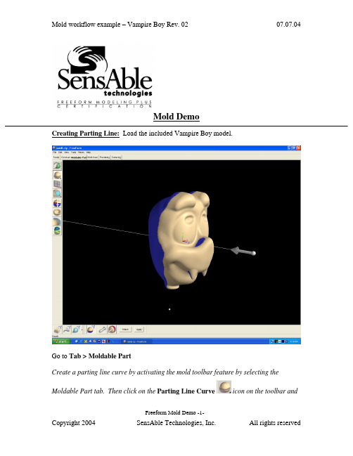
Mold DemoCreating Parting Line: Load the included Vampire Boy model.Go to Tab > Moldable PartCreate a parting line curve by activating the mold toolbar feature by selecting theMoldable Part tab. Then click on the Parting Line Curve icon on the toolbar andFreeform Mold Demo -1-click on the Show Parting Line Color icon to show the parting line. The arrow on the screen indicates the mold pull direction. You can change the direction by clicking onthe Set Direction icon to check the best parting line solution. Once everything is set, click on Apply to create the parting line curve.The parting line curve direction is already set for this model, but be sure the parting line draft angle is set to zero. To check if the draft angle is set to zero for this evaluation, go to Tools > Option > Parting line draft angle. For using the Parting Line tool, always set the draft to zero so that you will get a clear blue line. If the draft is not set to zero, the parting line curve will not be created in the correct location.Currently, the mold pull direction is already set correctly. If you want to show people the different pull direction, click on the Set Direction icon to change the setting.Showing Curvature PlotFreeform Mold Demo -2-The parting line curve is very dense and trying to pick up all the details necessary. If you want to look at the level of quality of the parting line curve, you can turn on the curvature plot and create a curvature plot of each curve. Go to:View > Design Curves -> Create Curvature Plots. Then click on the parting line curves on the model. By default, the plot is set in 2D to show the noise in Z direction only; you can also set to show the noise in X and Y direction by changing the 2D Curvature icon to 3D Curvature icon on the Dynabar. [as shown below]2D curvature plot showing on noise in Z directionFreeform Mold Demo -3-3D curvature plot showing noise in X and Y directionIn most cases, you will only want to use the 2D curvature plot in the Z direction. The number shown on the curvature plot indicates the minimum radius curvature of the curve. This number can be used to determine the tool size for machining in the future. To find the tool radius, simply take the inverse of the curvature value. The equation used in this calculation is shown below:C = 1/R ; C = curvature, R = radiusEditing Parting Line CurveFreeform Mold Demo -4-machining. To avoid this problem, I am going to smooth the parting line curve. Tosmooth the parting line curve, click on the Select icon on the toolbar and then clickon the parting line curve. Change the number on the Points box to reduce thenumber of points on the curve. In most cases, you can reduce the number of point by halfthen refit it. Be aware that it may have drifted from sharp details in the XY plane.Usually, after reducing the points on the parting line, the parting line will likely still be very close to the original parting line. However it does not work for every case. In most situations, you can just reduce the points and refit it just for demo purposes.Now I will refit the parting line curve by clicking on the Fit CurveFreeform Mold Demo -5-to Clay tool under the same flyout as the Parting Line Curve tool. Then click on the parting line curve. Refitting the curve will remove the curvature plot information because the refitted curve is actually a new curve. Therefore, you have to put the curvature plot back on to see the new result. Now you can see that the refitted curves have a low curvature and noise.You can also use the Smooth Curve tool under the Parting Line Curve tool to smooth out the curves. After you are satisfied with the result, you can turn off the curvature plot.Fixing DraftFor this model, there is a draft problem. To demonstrate the draft-fixing feature, youFreeform Mold Demo -6-should point out some draft problems on the model. Indicate the areas behind the nose and the teeth (Create Parting Line actually surrounded these areas with curves, which can be deleted at this time.)The next thing to do is to fix draft. As you can see on the screen, the nose and the tooth have a draft issue. To correct the problem, I can either add material or remove material to correct the problem under the Draft option.Go back to create moldable part and then select Draft tool on the toolbar. Then click on the parting line. The problem areas are shown in blue. Now I want to add material behind the nose to the fix the draft instead of chopping off the nose to fix the draft. So I click on the Add Clay , but hold to the parting line by clicking thePreserver Parting line icon then click Apply.The changes on the model should be very quick, so you can say a few words or gesturing with your hands, then the changes should be done. The fixed model is shown below.Freeform Mold Demo -7-Shelling The ModelClick on the “d” key to show the model in See Through mode, and indicate that it is a solid model. Click the “d” key once more to return to an opaque view.Now you can shell the model. Click on Shell on the toolbar. For this model, I want a 4mm shell. Then change the number in the Shell Thickness box on the dynabarto 4 and click Apply.Freeform Mold Demo -8-The shelling process should be done very quickly. While waiting for the model to be shelled, you can talk about the benefit of this feature. After the shell is complete, click on “d” on the keyboard again to activate the dotted mode for showing the part thickness.Click “d” to change to dotted mode to show part thicknessYou can check the part thickness by using the ruler feature. Go to Tools > Ruler or click“r” on the keyboard to activate the ruler feature. Then select Measure Thicknessicon on the Dynabar and measure the part thickness.Freeform Mold Demo -9-Creating Split JointFor better visual, turn off the clay by clicking on Blank Clay icon. The resulting screen is shown above. By turning off the clay, you can see the glue joint that you will create on the screen.Now I want to be able to create the shiplap joint. I go down to the Split Joint tool and pick on the curve on the screen. It will create a butt joint by default first (shown below) then I will create a shiplap joint on the modelFreeform Mold Demo -10-.After selecting the curve on the screen, a butt joint will be created. The creation of butt joint will not fail on this model. The shiplap joint properties box will pop up automatically when the butt joint is created.On the ShipLap Joint Properties box, set the values on the boxes to:-Offset value to 2mm because it’s a 4mm shiplap-Depth value to 2.5mm, just high enough that people can see the difference -Angle value to 5 degree so that it looks like in a angleFreeform Mold Demo -11-Ensure the Modify Region icon is selected on the dynabar then click on any two points on the outside curve of the model to define the region of the joint then click on any place on the curve within the region to create the split joint (as shown above).For the demo, create shiplap joint at only one place because for every place you do, you have to be able to select the inside curve of the split joint in the middle of the demo when you are doing Make Part and Make Insert. Therefore, to shorten the demo time and keep the audience’s attention, avoid creating more than one split joint.Next you want to show the Groove split joint feature, make an undo after the shiplap joint is created. Then select Groove Joint icon and the Groove Joint Properties box will appear.Freeform Mold Demo -12-Make sure the sum of the Offset value and the Width value does not exceed the width of the split joint, which is 4mm in this case. Otherwise, you will receive an error message. Once the values are entered, ensure the Create Split Joint icon is selected on the dynabar to create a groove joint on the entire curve. Then select the curve on the screen and a Groove Joint will be created (shown as below)Creating the groove joint for the demo is easier for the Make Part step later in the demo because you don’t have to pick the separate section all the way around the curve.Freeform Mold Demo -13-Freeform Mold Demo -14-Making PartNow I will separate the model into 2 parts, part 1 and part 2. I go to the Make Particon on the toolbar. Then select the Split Curve icon on the dynabar and click on the first split joint then the second split joint of the part. Next I click on the Part 1 Sideicon and click on the outside of the model(the face in this example) to select what is going to the part 1.When selecting the part 1 side, uncheck the Blank Clay to show the whole piece of clay. It’s easier in this way.Freeform Mold Demo -15-The first split joint is the outside curve of the part and the second split joint is the inside curve of the partThe first split joint is highlighted inFreeform Mold Demo -16-The second split joint is highlighted in green as shown on the rightnow look at the other part by selecting Work on Part of the other part in the Object List.Freeform Mold Demo -17-To turn on the object list, either click “o” on the keyboard or go to View > Object listOn the Object List, click on the part icon, and select Work On Part option to select the part that you want to work on.For the rest of the demo, we will work on one part of the model, Part 1 the face, though the other Part 2 can be done in a similar way.Freeform Mold Demo -18-Creating Mold InsertSo the next thing I will create an extent for the part, that is defining the actual mold insert dimensions, and create parting surfaces for the model.The extents can be resized to any dimension you need to fit into the mold. To resize it, you go to the set extents option (which is usually active when first entering the Mold Insert tab) and enter the XYZ values for the extents.To resize the extent, click on Create Mold Insert tab on the top of the workspace thenselect Mold Insert Properties and click on Set Extents icon on the Dynabar. Enter the desired dimension for the extent on the X,Y,Z boxes. For the demo, show people that the extent can be changed and set the numbers in the X,Y,Z boxes to a reasonable numbers. The following numbers are used for this demo:+X = 100.00, -X = -100.00+Y = 150.00, -Y = -150.00Freeform Mold Demo -19-+Z = 100.00, -Z = -100.00Freeform Mold Demo -20-Creating Extruded Parting SurfaceNext I will create the parting surfaces for the part. I go to the Extrude Parting Surfacetool then pick on two places on the curve to define the boundary. When you are picking the points to define the boundary, you don’t have to pick on the points, you can pick anywhere on the curve. The extruded surface can be created in a 45 degree angle. When extruding the surfaces from this example, extrude the surfaces perpendicularly from the form. For example, extrude it in a horizontal or vertical direction.Freeform Mold Demo -21-Creating Insert BlocksAfter the parting surface is completed, I will create a core insert block and a cavity insert blocks for the part. This can be done in a few steps.First I go to the Make Insert Blocks tool on the toolbar. Second, I pick the edge of the parting surface and the parting line. Finally, I select the side for the cavity block. To create insert blocks for the part:-Click on Parting Surface Curve icon on the Dynabar and select the edge of the extruded surface-Then select the parting line of the model (as shown below in green)Freeform Mold Demo -22--Click on Cavity Side icon on the dynabar and select the cavity side of the model.-Once the cavity side is selected, a plane will appear on the screen to represent the bottom of the cavity block.o Notes: Don’t zoom to close to the model; otherwise you will not be able to see the plane.o Notes: If you selected the top part as the cavity side, then the plane should be placed on the topside or on the bottom side if the bottom part isselected as the cavity side.- A window will pop up and asks if the plane is placed correctly, click “Yes” if the plane location is correct or “No” if the plane location is incorrect…Freeform Mold Demo -23-shown below)…Freeform Mold Demo -24-From here, I have two insert blocks, one for the core and the other one for the cavity. I can look at either one of the blocks by selecting it on the Object List.To look at the core block:-Turn on the object list and click on the core mold insert icon, and select Work On Component option-This will hide the cavity side component automatically.Freeform Mold Demo -25-Freeform Mold Demo -26-You can turn off “See Through Clay” option by View > Design Curve > See Through Clay for people easier to see to blockFreeform Mold Demo -27-Reverse Engineering the Core FaceThe next thing I will do is to create patch surface for the core. After I create the patches, I can export the file to other CAD software to build other components on the mold insert such as runners systems, water lines, sprues, and ejection pins, etc. To create the patch, I draw curves that defined the patch boundary on the core. Then using the Patch toolon the toolbar to create the batch surfaces for the core.Freeform Mold Demo -28-To draw curves defining the patch boundary on the core:-Select Draw tool under Parting Line tool-Ensure the Fit on Create icon is selected on the dynabaro Notes: DO NOT select Split on Create icon on the dynabar because it will destroy the surfaces by separating the curve into two-Turn on See Through Clay option by: View > Design Curves > See Through Clay (if you find it to be easier).-Start drawing curve on the model to cover up the entire core (as shown above)Freeform Mold Demo -29-To create patches on the core surface:-Once the curves are drawn on the surface, select the Patch tool-Ensure Fit to Clay and Manual Boundary Select icons are selected on the dynabaro Notes: Selecting the Fit to Clay icon will create patches that are more tightly fitted on the clay surface than using the Fit to Boundary icon . -Click on the curves in sequence to define the boundary of the patch. Once you are done the patches, go to the object list and folder the patches you create and label the folder something meaningful. You will need to refer to this folder later.Freeform Mold Demo -30-Exporting IGESOnce the Core side of Part 1 is patched, it can be exported as an IGES file for further modification in other CAD software.To export an IGES file of the Core side:Go to File > Export > Curves and Patches, then check the following information in the dialog box that appears:Freeform Mold Demo -31-…which will write an IGES file for CAD import. To export an STLfile of each of the blocks of the insert, for rapid prototyping:For the core, turn off the display of all Clay and Curves using the lower left display control:Then go to File > Export > Model, then, it will export the patches which will be subdivided to create polygons out of the patches.Usually, the default has adequate details when exporting the STL polygon file but if you want more detail, go to Patch Display Properties under the Blank Patches icon onFreeform Mold Demo -32-the Dynabar.Freeform Mold Demo -33-Changing the Display Resolution to High in thePatch Display Properties will give you a muchfiner tessellation of the patches.You can verify your results by reading the fileback in as an STL import and preview (but don’tkeep it, just preview it as below…Note: When exporting the Cavity side, you don’t want the Split Joint patches or the core face patches visible. On the Object list, do a “work on component” on the cavity component first, then hide the Split Joint Curves and Split Joint Patches folders as shown on the right. Find the folder you created for the Core face reverse engineering patches and hide it as well.Creating ElectrodeCreating electrode off the cavity is not something that is automatically created but it is not too difficult to do. First you want to turn off the surfaces and build a plane to project the parting line onto the plane. Then draw a line to connect the curves and create a patch for the side. Once the patch is created, export it as an electrode.To Create Electrode Off the Back Cavity Block:Go to the Object list then turn off the surfaces of the core and cavity blocks and the parting surfaces as shown below.Then select New Plane/Sketch on the toolbar to create a plane. The distance between the part and the plane is equal to the distance of the side of the electrode.Select Project Curve to Plane from the flyout of the Parting line curve tool on the toolbar. Then click on the parting line curves and touch the plane. The curves will then be projected onto the plane (as shown below). Once the curve is projected, you can hide the plane on the object list.Freeform Mold Demo -34-Next select Draw from the Parting line curve tool on the toolbar. Make sure the Fit on Create icon on the dynabar is deselected because you want to make a square patch. Then draw a line connected the parting line and the projected parting line.For this model, a patch can be built with only two main curve segments (as shown below)Freeform Mold Demo -35-Freeform Mold Demo -36-dynabar so that a straight extrusion can be created. Then select the curves in sequence to create the patches (as shown below)Once the side patches are created, you can make a patch for the back but for electrodes the back patch is not required. Then export it as an STL file for tooling the electrode.。
FreeFrom软件操作说明
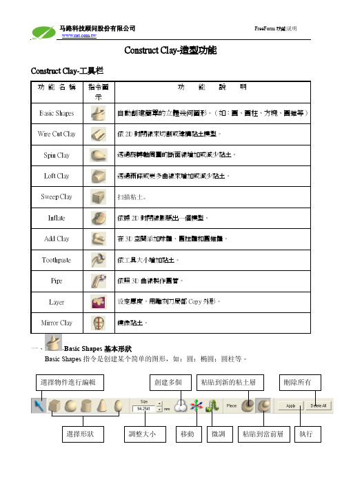
Construct Clay-造型功能Construct Clay-工具栏一、-Basic Shapes 基本形狀Basic Shapes 指令是创建某个简单的图形,如:圆;椭圆;圆柱等。
二、Wire Cut Clay形体切割功能01.当2D 平面上有绘制任何的2D线段,我们可以使用Wire Cut Clay来挖除所需的深度。
02.点选Wire Cut Clay后,再点选2D Sketch上的线条。
03.请在下列的对应工具栏中,输入所要挖除的深度。
输入所要挖除的深度Raise Lower04.再点选Lower指令,即可完成挖除的动作。
※亦可选择Raise来长出对象。
使用Wire Cut Clay設定深度,完成切割動作。
05.选择距离的计算方式。
边界的斜度依据两个平面的距离计算依据第一个平面与粘土之间的距离计算06.Wire Cut Clay除了可以切割深度外,也可以切割对象外观。
Create Inside在线段范围内长出材料Cut Inside切除线段范围内的材料Cut Outside切除线段范围外的材料三、Spin Clay依2D线旋转粘土功能制作在另外一个层制作在当前层长出粘土切除粘土隐藏/显示2D平板01.开启新的绘图平板,并在上面绘制欲建构模型的断面线及中轴线。
02.点选Spin Clay功能,选择Create Inside选项,以建构出所要的模型。
※斷面線必須為封閉線段,中心轴必须是直线。
四、Loft造型功能點選繪圖平板載入導引線預覽載入斷面調整導引線取消01. 使用Loft功能時,必須先使用2張以上的繪圖平板繪製出輪廓斷面線,並設定距離。
02. 點選Select Ste p,選擇上一步驟所定義的輪廓線,將出現下圖的預覽結果。
03. 點選Section Ste p,可在模型任意位置載入新的斷面線。
04. 點選Guide Ste p,可在斷面線之間載入導引線。
05. 點選Shape Ste p ,可根據所需造型進行斷面線和導引線的調整。
FreeFrom软件操作说明
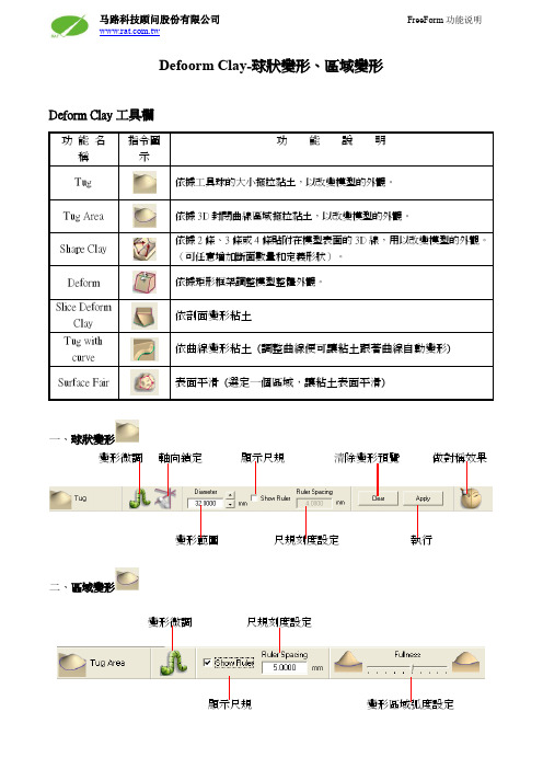
Defoorm Clay-球狀變形、區域變形
Deform Clay工具欄
一、球狀變形
變形微調軸向鎖定顯示尺規清除變形預覽做對稱效果
變形範圍尺規刻度設定執行
二、區域變形
變形微調尺規刻度設定
顯示尺規變形區域弧度設定
曲線定義造型
三、曲線定義造型
Shape Clay 指令是利用兩條、三條或四條封閉的3D 曲線,通過調整使用者定義的剖面,從而改變曲線區域內模型的形狀。
它可分為三個步驟進行: 1. 選擇邊界曲線 2. 指定剖面位置 3. 調整形狀
步驟一:選擇邊界曲線
步驟二:指定剖面位置
(快捷鍵Z)
(快捷X)
(快捷鍵C)
步驟三:調整形狀
框架定義變形
四、框架定義變形
框架定義模式 座標位置微調 同步鏡射調整 順化變形 進階調整 清除 確認
單方向調整 同方向調整 斜面變形 將框架調整和視角成水準
Advanced 進階調整選單:
順向調整 線性調整 分離調整
寬度設定
框架四周同步調整
剖面定義變形
五 、依剖面变形粘土
依剖面旋转变形
依曲线排列变形
六 、依曲线变形粘土
(调整曲线便可让粘土跟着曲线自动变形)
画曲线到鼻子和眉毛上面 执行指令后调整曲线,粘土将自动调整 注:使用此指令时,3D 曲线不能贴附粘土上。
七、 Surface Fair 表面平滑 (选定一个区域,让粘土表面平滑)。
FreeForm软件教程-V10新增功能详解
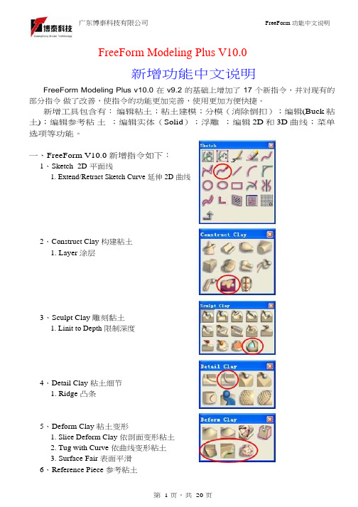
第 4 页,共 20 页
广东博泰科技有限公司
FreeForm 功能中文说明
勾选
不勾选
Profile Orientation 方向定位
Clay Surface
依粘土表面方向计算
Buck Surface
依 Buck 粘土表面方向计算
Current Pull Direction 依当前拔模方向计算
Parallel
Place slices at curveedit points - 根据曲线的编辑点产生 剖面。
Reset - 按重置以清除所有的数值,重新布 置剖面。 Create Slices - 创建剖面。
第 6 页,共 20 页
广东博泰科技有限公司
FreeForm 功能中文说明
Interpolated:
Construct Clay:
1、
Layer 涂层
设定厚度,用雕刻刀局部 Copy 外形(Copy 后与原有的粘土相连在同一物件)
Example
Sculpt Clay:
(Clay)粘土
(Buck)粘土
第 3 页,共 20 页
广东博泰科技有限公司
FreeForm 功能中文说明
1、
Linit to Depth 限制深度 (设定一个深度,方便在雕刻粘土时不会超过此深度)
广东博泰科技有限公司
1. Edit and Stitch Reference Piece 编辑参考粘土并缝合
2. Slice Deform Reference 依剖面变形参考粘土
3. Tug with Curve 依曲线变形参考粘土
7、 Patches / Solids 曲面/实体 1. Edit and Stitch Solid 编辑实体并缝合
FreeFrom软件操作说明
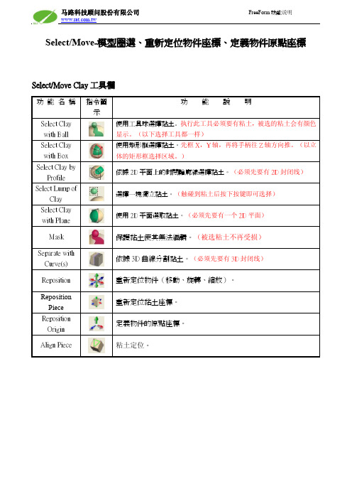
Select/Move-模型圈選、重新定位物件座標、定義物件原點座標Select/Move Clay工具欄
一、Mask模型表面遮罩
Mask指令是用來定義粘土的屬性(使粘土無法編輯)。
使用者自定義選擇使用圖片來圈選
二、Reposition Piece:重新定位物件座標
座標位置微調旋轉鎖定在世界座標系移動
平移軸向鎖定鎖定在物件座標系移動離開三、Reposition Origin:重新定位原點座標
座標位置微調平移軸向鎖定鎖定在世界座標系移動
設定原點座標於重心位置旋轉鎖定在物件座標系移動鎖定在曲面法線
方向
四、Align Piece:粘土定位
当粘土定位时,可在粘土或3D曲线或2D Plane上面任意选三个点来定义一个平面,然后再以这个平面为基准转到某一个方向;也可直接根据轴向来定义方向;同时可以使用Object菜单里现有的2D Plane为基准来定位,这样会比选三个点定位更方便。
FreeForm V 新增功能说明 FreeForm Modeling lus软件教程
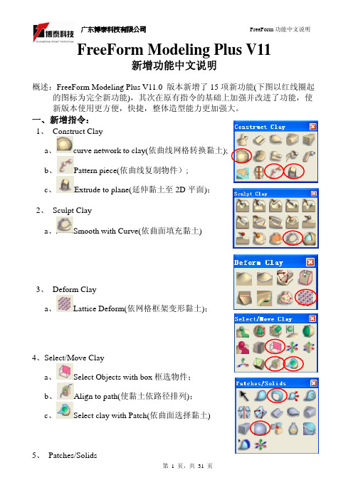
FreeForm Modeling Plus V11新增功能中文说明概述:FreeForm Modeling Plus V11.0 版本新增了15项新功能(下图以红线圈起的图标为完全新功能),其次在原有指令的基础上加强并改进了功能,使新版本使用更方便,快捷,整体造型能力更加强大。
一、新增指令:1、 Construct Claya、curve network to clay(依曲线网格转换黏土);b、Pattern piece(依曲线复制物件);c、Extrude to plane(延伸黏土至2D平面);2、 Sculpt Claya、Smooth with Curve(依曲面填充黏土)3、 Deform Claya、Lattice Deform(依网格框架变形黏土);4、Select/Move Claya、Select Objects with box框选物件;b、Align to path(使黏土依路径排列);c、Select clay with Patch(依曲面选择黏土)5、 Patches/Solidsa 、Create Ring Patch(依两条环形曲线建曲面);b 、Curve network to Solid(依曲线网格转换实体);6、Analysis Toolsa 、Analysze Fit (分析黏土贴附程度); b、Analysze Inter s ection (分析相交黏土); c 、Analysze Thickness (分析黏土厚度)d 、Dimensional Bounding Box (显示黏土的空间边界);e 、Ruler(3D 测试);二、新增指令功能详细说明:1、curve network to clay(依曲线网格转换黏土);2、Pattern piece(依曲线复制物件)微调旋转物体方向移动锁定轴向从曲线端点排列最后一个物件的比例生成新的图层旋转方式选择球珠和3D 线,设定球珠数量。
FreeFrom软件操作说明
19.右圖為使用 QuickTime VR 選項所運算出的結果。
马路科技顾问股份有限公司
FreeForm 功能说明
二、 在 2D 平面上定義背景圖片 貼圖檔名 贴图数量设定 渲染
貼圖路徑瀏覽
清除貼圖
※注意:指定貼圖之後,並無預覽功能,要執行 Render 之後才能看到貼圖影像。
08.點選
Custom Lighting 光源種類 光源開啟 光源色彩 倒影設定
進入光源設定選項。 09.光源設定的燈光種類共有 3 種: Point Light:點光源 Spot Light:聚光燈 Infinite Light:強光
马路科技顾问股份有限公司
FreeForm 功能说明
此種模式將會 render 出單張的影像檔,可儲存的格式 有 BMP、JPEG、TIFF 等常見的影像格式。
此種模式將不會進行 render 運算,而是將 3D 模型、材質 和燈光等設定值儲存為*.mi 的格式,讓使用者可以利用 Softimage 匯入此檔案而去進行 render 運算,使得 FreeForm 依然可以繼續建構 3D 模型的工作。
马路科技顾问股份有限公司
FreeForm 功能说明
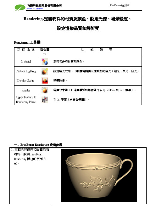
Rendering-定義物件的材質及顏色、設定光源、場景設定、 設定渲染品質和解析度
Rendering 工具欄
功 能 名 稱 指令圖 示 Material Custom Lighting Display Scene Render Apply Texture to Rendering Plane
10.本範例所使用的光源種類 為聚光燈(Spot Light) 。
11.點選
Display Scene 進 場景種類 場景大小
- 1、下载文档前请自行甄别文档内容的完整性,平台不提供额外的编辑、内容补充、找答案等附加服务。
- 2、"仅部分预览"的文档,不可在线预览部分如存在完整性等问题,可反馈申请退款(可完整预览的文档不适用该条件!)。
- 3、如文档侵犯您的权益,请联系客服反馈,我们会尽快为您处理(人工客服工作时间:9:00-18:30)。
Thickness – 在凸条底面延长一个厚度。
第 4 页,共 20 页
广东博泰科技有限公司
FreeForm 功能中文说明
勾选
不勾选
Profile Orientation 方向定位
Clay Surface
依粘土表面方向计算
Buck Surface
依 Buck 粘土表面方向计算
二、新增指令功能详细说明:
第 2 页,共 20 页
广东博泰科技有限公司
FreeForm 功能中文说明
Sketch:
1、
Extend/Retract Sketch Curve 延伸 2D 曲线
曲线的延伸方式
延长现有的曲线 延长的部分成另一条曲线
曲线长度
细部说明:
Tangent Reflection Curvature Tangent(to point)
缝合
不勾选时将在当前的参考粘土上进行缝合;勾选时将 Copy 一个参考粘土层 第 8 页,共 20 页
广东博泰科技有限公司
Example
FreeForm 功能中文说明
2、
Slice Deform Reference 依剖面变形“参考粘土”
注:(此指令用法同上,区别只是在于一个针对粘土,一个针对“参考粘土”,
3、
Plane to Clay Intersection Curve 粘土和平面求交线
软件自动计算编辑点数量
使用最大限度
直接设定编辑点数量
使用默认的控制点数量
使用最大限度
直接设定控制点数量
剖面公差
4、
Surface to Clay Intersection Curve 曲面和粘土求交线(其选项菜单同
Construct Clay:
1、
Layer 涂层
设定厚度,用雕刻刀局部 Copy 外形(Copy 后与原有的粘土相连在同一物件)
Example
Sculpt Clay:
(Clay)粘土
(Buck)粘土
第 3 页,共 20 页
广东博泰科技有限公司
FreeForm 功能中文说明
1、
Linit to Depth 限制深度 (设定一个深度,方便在雕刻粘土时不会超过此深度)
Mode 延伸方式
曲线端点由切线 tangent(G1)方式延伸 曲线端点由曲率 curvature(G2)方式延伸,延长的曲线将自动增加 控制点(不影响原有的控制点数量,自动新增控制点) 曲线端点由曲率 curvature(G2)方式延伸,延长的曲线控制点不新 增(原有的控制点重新排列,不增加数量) 曲线端点由切线 tangent(G1)方式延伸,延伸部分曲线终点位置可 任意设定
Position Linits:
Upper –拖动滑块来指定顶端剖面的位置,默认是 100%。 Lower - 拖动滑块来指定末端剖面的位置,默认是 0%。 Spine Axis Offset–以曲线为中心轴,剖面可依据 X,Y,
Z 三个轴向偏移位置。
Arrangement :
Nunber of slices – 指定使用若干个剖面,50 片是默认值, 剖面数量多会使粘土更顺畅。
4、Detail Clay 粘土细节 1. Ridge 凸条
5、Deform Clay 粘土变形 1. Slice Deform Clay 依剖面变形粘土 2. Tug with Curve 依曲线变形粘土 3. Surface Fair 表面平滑
6、Reference Piece 参考粘土
第 1 页,共 20 页
FreeForm 功能中文说明
8、 Mold 分模 1. Fix Draft Selection 局部消除倒扣
9、 Tweening 管理步骤 1. Duplicate Active Piece 复制一个激活的粘土层 2. Create Base Step Floder 创建一个基础资料夹 3. Create Next Step Folder 创建下一步的资料夹 4. Generate Steps 同时产生多个步骤的资料夹
Space between slices – 指定剖面间隙,剖面越分散时 变形越多。
Place slices at curveedit points – 根据曲线的编辑点产生 剖面。
Reset - 按重置以清除所有的数值,重新布置剖面。 Create Slices - 创建剖面。
第 6 页,共 20 页
建立粘土层副本 创建一个基础步骤资料夹 创建下一个步骤的资料夹 同时产生多个步骤的资料夹 激活 Base 粘土层 往前翻动激活粘土层 往后翻动激活粘土层 激活 Final 粘土层
Object List:
1、 Object List\Intersect With…… 布尔运算(求两块粘土之间的相交处)
依曲线排列变形
Spine Axis:
Use Global Axis - 设定剖面沿着 X,Y 或 Z 轴排列,Y 轴 是默认值。
Use Curve as Axis - 剖面根据曲线排列。 Orient Slices to Curve Tangent - 勾选此选项时,两头的剖
面将转到与曲线垂直方向。
Duplicate Active Piece Create Base Step Floder Create Next Step Folder Generate Steps Goto Base Step Goto Previous Step Goto Next Step Goto Final Step
详细功能说明请参考
此指令)。
3、
Tug with Curve 依曲线变形“参考粘土”
半径
变形区域侧面的形状
高品质 微调 锁定轴向 取消 执行
Patches/Solids:
1、
Edit and Stitch Solid 编辑实体并缝合
注:(此指令的详细功能请参考
Edit and Stitch Reference Piece)
Apply – 执行
2、
Tug with Curve 依曲线变形粘土 (调整曲线便可让粘土跟着曲线自动变形)
半径
变形区域侧面的形状
高品质 微调 锁定轴向 取消 执行
第 7 页,共 20 页
广东博泰科技有限公司
FreeForm 功能中文说明
画曲线到鼻子和眉毛上面 注:使用此指令时,3D 曲线不能贴附粘土上。
输入深度
设置
取消
Detail Clay:
1、
Ridge 凸条
2D 轮廓线
编辑轮廓
左右反转
上下反转
使用上次的设定 方向定位 执行
Settings 细部说明:
Size:
Thickness - 输入数值确定凸条的厚度,或按向上和向 下箭头以增加或减少当前的数值。
Width – 输入数值确定凸条的宽度。 Fixed Aspect - 单击 Fixed Aspect 后,厚度成灰色并将
自动决定,宽度任意修改。
Taper Ends:
Width 1 - Width 2 – 渐变效果:输入起始点和终止点宽 度不一致的数值,得到渐变效果。
Swap Ends - 反转起始点和终止点宽度的数值。
Offset Above Surface:
Thickness - 设定凸条距离粘土表面间隔一个厚度。
(剖面排列跟着翻转),默认是取消。 Align Curve to Object –选择曲线的起始点或终止点排列
剖面。 Stert Offset – 指定一个数值,使剖面由曲线起始点开始
偏移位置。 Rotation – 指定一个数值旋转所有剖面,默认值为 0 。
Select Curve - 激活 Conform to Curve 模式,当您选择一个 三维曲线时,您会看到剖面将定位成一个预览 变形效果。
是 50 的。
Use the Phantom to Scale,Translate,or Rotate the Target
Slice Plane - 使用手柄缩放,移动,旋转,或翻剖面以 变形粘土。
Conform to Curve :
单击 Select Curve 来激活(Conform to Curve 菜单)。 Scale Object to Curve Length – 勾选时剖面随着曲线长度
广东博泰科技有限公司
FreeForm 功能中文说明
FreeForm Modeling Plus V10.0
新增功能中文说明
FreeForm Modeling Plus v10.0 在 v9.2 的基础上增加了 17 个新指令,并对现有的部分指令 做了改善,使指令的功能更加完善,使用更加方便快捷。
新增工具包含有: 编辑粘土;粘土建模;分模(消除倒扣);编辑(Buck 粘土);编辑参考粘 土 ;编辑实体(Solid);浮雕 ;编辑 2D 和 3D 曲线;菜单选项等功能。
执行指令后调整曲线,粘土将自动调整
3、
Surface Fair 表面平滑 (选定一个区域,让粘土表面平滑)
U V 方向的顺滑程度
边界是否要顺滑
预览
显示网格
取消 执行
Example
Reference Piece:
1、
Edit and Stitch Reference Piece 编辑参考粘土并缝合
选曲线 选粘土 设定粘土精度 粘土厚度 预留边界 转换粘土 选边界 选粘土
排列;不勾选时剖面排列将短于曲线长度。 Travel Backwards(End to Start) –勾选时,曲线终点处缩进 (推向起始点);不勾选时,终点不缩短。(注:此项要 在不勾选 Scale Object to Curve Length 的情况下方能看 出效果) Reverse Curve(to Flip Object) – 翻转曲线的起始和终止点