FCR4.0M5中文资料
M4、M5铣床作业指导书
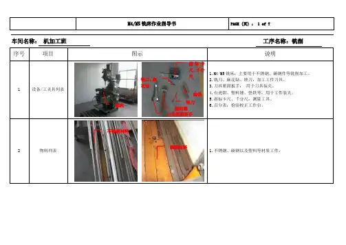
车间名称: 机加工班 工序名称:铣削
铣床
碳钢材料
不锈钢材料
垫铁
锉刀
游标卡尺、千分尺
刀具紧固扳手
塑料锤 铣刀、麻花钻
产品检验标准总工时:根据工件图纸技术要求决定
具体操作步骤
挑选母材
切割下
料
工件装夹
工件装夹
铣床断路器开关
铣床主电源开关
M4铣床刀具装夹
横向进给自动进给速度调节旋钮
主轴转速调节
安装直线检测
工作台纵向进给手柄
工作台横向进给手柄 刀具与工件轻碰
工作台径向自动进给按钮
工作台径向进给手柄
主轴开关
数显表
1.身体、手被工件铁屑烫伤、绞伤等
2.脚被工件、工具砸伤。
3.误操作造成的伤害等。
检测
检测
关闭设备电源关闭设备主电源开关
操作流程图。
三菱FX系列PLC简介及型号说明
三菱FX系列PLC简介及型号说明第一篇:三菱FX系列PLC简介及型号说明三菱FX系列PLC简介及型号说明FX系列PLC是由三菱公司近年来推出的高性能小型可编程控制器,以逐步替代三菱公司原F、F1、F2系列PLC产品。
其中FX2是1991年推出的产品,FX0是在FX2之后推出的超小型PLC,近几年来又连续推出了将众多功能凝集在超小型机壳内的FX0S、FX1S、FX0N、FX1N、FX2N、FX2NC等系列PLC,具有较高的性能价格比,应用广泛。
它们采用整体式和模块式相结合的叠装式结构。
一、FX系列PLC型号的说明FX系列PLC型号的含义如下:其中系列名称:如0、2、0S、1S、ON、1N、2N、2NC等单元类型:M──基本单元E──输入输出混合扩展单元Ex──扩展输入模块EY──扩展输出模块输出方式:R──继电器输出S──晶闸管输出T──晶体管输出特殊品种:D──DC电源,DC输出A1──AC电源,AC (AC100~120V)输入或AC输出模块H──大电流输出扩展模块V──立式端子排的扩展模块C──接插口输入输出方式F──输入滤波时间常数为1ms的扩展模块如果特殊品种一项无符号,为AC电源、DC输入、横式端子排、标准输出。
例如FX2N-32MT-D表示FX2N系列,32个I/O点基本单位,晶体管输出,使用直流电源,24V直流输出型。
第二篇:三菱PLC型号说明[小编推荐]三菱PLC型号型号功能说明FX1N-60MR-001 输入点:36,24点继电器输出FX1N-40MR-001 输入点:24,16点继电器输出 FX1N-24MR-001 输入点:14,10点继电器输出 FX1N-14MR-001 输入点:8,6点继电器输出FX1N-60MR-D 输入点:36,24点继电器输出(直流供电)FX1N-40MR-D 输入点:24,16点继电器输出(直流供电)FX1N-24MR-D 输入点:14,10点继电器输出(直流供电)FX1N-60MT-001 输入点:36,24点晶体管输出FX1N-40MT-001 输入点:24,16点晶体管输出FX1N-24MT-001 输入点:14,10点晶体管输出FX1N-14MT-001 输入点:8,6点晶体管输出FX1N-60MT-D 输入点:36,24点晶体管输出(直流供电)FX1N-40MT-D 输入点:24,16点晶体管输出(直流供电)FX1N-24MT-D 输入点:14,10点晶体管输出(直流供电)FX1NC-16MT 输入点:8,8点晶体管输出 FX1NC-32MT 输入点:16,16点晶体管输出FX1S-30MR-001 输入点:16,14点继电器输出FX1S-20MR-001 输入点:12,8点继电器输出 FX1S-14MR-001 输入点:8,6点继电器输出 FX1S-10MR-001 输入点:6,4点继电器输出FX1S-30MR-D 输入点:16,14点继电器输出(直流供电)FX1S-20MR-D 输入点:12,8点继电器输出(直流供电)FX1S-14MR-D 输入点:8,6点继电器输出(直流供电)FX1S-10MR-D 输入点:6,4点继电器输出(直流供电)FX1S-30MT-001 输入点:16,14点晶体管输出FX1S-20MT-001 输入点:12,8点晶体管输出FX1S-14MT-001 输入点:8,6点晶体管输出 FX1S-10MT-001 输入点:6,4点晶体管输出FX1S-30MT-D 输入点:16,14点晶体管输出(直流供电)FX1S-20MT-D 输入点:12,8点晶体管输出(直流供电)FX1S-14MT-D 输入点:8,6点晶体管输出(直流供电)FX1S-10MT-D 输入点:6,4点晶体管输出(直流供电)FX1N-1DA-BD 1路D/A FX1N-2AD-BD 2路A/D FX1N-2EYT-BD 扩展板,2点晶体管输出FX1N-4EX-BD 扩展板,3点输入 FX1N-8AV-BD 扩展板,8路电位器FX1N-232-BD RS-232通讯板(1CH)FX1N-422-BD RS-422通讯板(1CH)FX1N-485-BD RS-485通讯板(1CH)FX1N-CNV-BD 转换用接头 FX1N-EEPROM-8L PLC存储盒---------型号功能说明FX2N-128MR-001 输入点: 64,64 继电器输出 FX2N-80MR-001 输入点: 40,40 继电器输出 FX2N-64MR-001 输入点: 32,32 继电器输出FX2N-48MR-001 输入点:24,24 继电器输出FX2N-32MR-001 输入点: 16,16 继电器输出 FX2N-16MR-001 输入点: 8,8 继电器输出FX2N-80MR-D 输入点:40,40 继电器输出(直流供电)FX2N-64MR-D 输入点:32,32 继电器输出(直流供电)FX2N-48MR-D 输入点:24,24 继电器输出(直流供电)FX2N-32MR-D 输入点: 16,16 继电器输出(直流供电)FX2N-128MT-001 输入点:64,64点晶体管输出 FX2N-80MT-001 输入点: 40,40点晶体管输出FX2N-64MT-001 输入点:32,32点晶体管输出FX2N-48MT-001 输入点: 24,24点晶体管输出 FX2N-32MT-001 输入点: 16,16点晶体管输出 FX2N-16MT-001 输入点: 8,8点晶体管输出FX2N-80MT-D 输入点:40,40点晶体管输出(直流供电)FX2N-64MT-D 输入点:32,32点晶体管输出(直流供电)FX2N-48MT-D 输入点:24,24点晶体管输出(直流供电)FX2N-32MT-D 输入点: 16,16点晶体管输出(直流供电)FX2NC-96MT 输入点:48,48点晶体管输出 FX2NC-64MT 输入点: 32,32点晶体管输出FX2NC-32MT 输入点: 16,16点晶体管输出 FX2NC-16MT 输入点:8,8点晶体管输出 FX2N-48ER 输入点:24,24 继电器输出 FX2N-48ET 输入点:24,24点晶体管输出 FX2N-32ER 输入点:16,16 继电器输出 FX2N-32ET 输入点:16,16点晶体管输出 FX2N-16EX 输入点:16 FX2N-16EYR 输入点:16 继电器输出 FX2N-16EYT 输入点:16点晶体管输出 FX2N-8ER 输入点:4,4 继电器输出 FX2N-8EX 输入点:8 FX2N-8EYR 输入点:8 继电器输出FX2N-8EYT 输入点:8点晶体管输出FX2NC-32EX 输入点:32 FX2NC-32EYT 输入点:32点晶体管输出FX2NC-16EX 输入点:16 FX2NC-16EYT 输入点:16点晶体管输出FX2NC-16EX-T 输入点:16 FX2NC-16EYR-T 输入点:8 继电器输出第三篇:三菱PLC分类及型号的基础知识三菱PLC分类及型号的基础知识三菱PLC的发展历程:1、1980-1990 三菱PLC主要有FF1F2系列小型PLC,K/A系列中、大型PLC2、1990-2000 三菱PLC主要分为FX系列小型PLC,A 系列(A2SA2USQ2A)中大型PLC3、2000以后,三菱PLC主要分分为FX系列小型PLC,Q系列(QnQnPH)中大型PLC三菱FX系列PLC介绍:FX系列PLC包括FX1S FX1N FX2N FX3U四种基本类型的PLC,早期还包括FX0系列产品。
施奈德EOCR保护器新产品中文版
Emission
& 7
i3DM / iFDM, i3MZ/iFMZ, i3MS/iFMS, i3M420/iFM420, i3BZ/iFBZ
0.5~60A, 60A ,
i3MS/iFMS 0.5~20A, 20A ,
& TCC 0.5~32A, 32A
i3BZ iFBZ
2
0.5A
D-time O-time
3BZ2 / FBZ2 AC/DC 100~240V
DC/AC 24V 50/60 Hz
i3DM / iFD AC/DC 100~2
DC/AC 24 50/60 Hz
A, F, H
5 Digit 7 Segment -
/ 3DD, 3DE, 3DM FD, FDE, FDM
-
5 Digit 7 Segment -
DC/AC 24V 50/60 Hz
i3MZ / iFMZ AC/DC 100~240V
DC/AC 24V 50/60 Hz
i3BZ / iFBZ AC/DC 100~240V
DC/AC 24V 50/60 Hz
i3M420 / iFM420 AC/DC 100~240V
DC/AC 24V 50/60 Hz
EOCR-iFDM (Z, S, 420) Window type
EOCR-iFDM (Z, S, 420, BZ) Bottom hole type
EOCR-i3DM (Z, S, 420, BZ) Terminal type
EOCR-iFDM (Z, S, 420, BZ) Terminal type
IEC61000-4-2 IEC61000-4-3 IEC61000-4-6 IEC61000-4-4 IEC61000-4-5 CISPR11
迈克罗斯 47007-0005450 远程控制器用户指南说明书
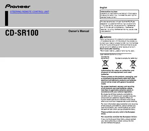
For countries outside the European Union:
If you wish to discard these items, please contact your local authorities or dealer and ask for the correct method of disposal.
• If you must operate this unit while driving, do not take your eyes off the road or an accident could result.
• If any of the following problems occur, immediately stop using this unit and consult your dealer from whom you purchased this unit: – smoke coming from the unit. – abnormal odors or smells. – a foreign object has entered the unit. – liquid has been spilled on or into the unit. If you continue to use the unit when it is not operating properly, damage could result in an accident or fire.
Notes
• Depending on the car stereo, there may not be some buttons with the same names as those on this unit.
XMC4000中文参考手册-第06章 灵活的CRC引擎(FCE)
灵活的CRC引擎(FCE)6 灵活的CRC引擎(FCE)FEC提供一个循环冗余码(CRC)算法的并行执行。
现行XMC4500微控制器的FCE版本能实现符合IEEE802.3的以太网CRC32,CCITT的CRC16和SAE J1850的CRC8多项式算法。
FCE的基本目标是作为一个为使用CRC识别标志的软件应用或操作系统服务的硬件加速引擎。
FCE作为一个标准外围总线从设备操作,通过一组配置和控制寄存器实现完全控制。
不同的CRC算法彼此相互独立,它们可以同时用在不同的软件任务上。
注:在6-11页描述为“寄存器”的FCE内核寄存器名称是参考于一个产品参考手册上的模块名称前缀“FCE_”。
参考文献[5] 一个无痛的CRC错误检测算法指南,Ross N.Williams[6] 互联网应用的32字节CRC,Philip Koopman,独立系统和网络(DSN)国际会议,2002相关标准和规范[7] IEEE 802.3 的以太网32位CRC表6-1 FCE涉及的缩写词CRC 循环冗余码FCE 灵活的循环冗余码引擎IR 输入寄存器RES 结果STS 状态CFG 配置6.1 概述本节提供了FCE模块的功能,应用和逻辑结构的概述。
6.1.1 功能FCE提供如下功能:• FCE执行如下的循环冗余码多项式:灵活的CRC引擎(FCE)— CRC内核0和1:IEEE802.3 CRC32以太网多项式:0x04C11DB71) - x32+x26+x23+x22+x16+x12+x11+x10+x8+x7+x5+x4+x2+x+1 —CRC内核2:CCITT CRC16 多项式:0x1021 - x16+x12+x5+1— CRC内核3:SAE J1850 CRC8多项式:0x1D - x8+x4+x3+x2+1• 并行CRC实现—通过FCE计算的数据块会是一个多重二次多项式—通过FCE计算的数据块的开始地址会被排列到二次多项式中• 寄存器接口:— 输入寄存器— CRC寄存器— 配置寄存器启用控制CRC操作和对信息的末端进行自动校验。
爱立信PDG13C0045TFFN电子保护模具断路器说明说明书
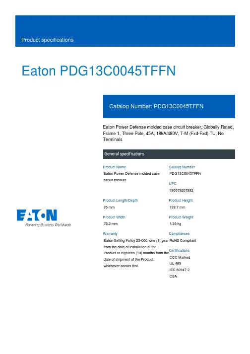
Eaton PDG13C0045TFFNEaton Power Defense molded case circuit breaker, Globally Rated, Frame 1, Three Pole, 45A, 18kA/480V, T-M (Fxd-Fxd) TU, No TerminalsEaton Power Defense molded case circuit breakerPDG13C0045TFFN 78667920793276 mm 139.7 mm 76.2 mm 1.36 kg Eaton Selling Policy 25-000, one (1) year from the date of installation of theProduct or eighteen (18) months from thedate of shipment of the Product,whichever occurs first.RoHS Compliant CCC MarkedUL 489IEC 60947-2CSAProduct NameCatalog Number UPCProduct Length/Depth Product Height Product Width Product Weight WarrantyCompliancesCertifications45 AComplete breaker 1Three-polePD1 Global Class A T-M (Fxd-Fxd) TU600 Vac600 VNo Terminals18 kAIC at 480 Vac 10 kAIC Icu @250 Vdc 18 kAIC @480V (UL)20 kAIC Icu/ 20 kAIC Ics/ 42 kAIC Icm @380-415V (IEC) 10 kAIC @600V (UL/CSA) 10 kAIC Icu @125 Vdc25 kAIC Icu/ 25 kAIC Ics/ 52.5 kAIC Icm @240V (IEC) 25 kAIC @240V (UL)Eaton Power Defense MCCB PDG13C0045TFFN 3D drawing Consulting application guide - molded case circuit breakers Power Defense technical selling bookletPower Defense molded case circuit breaker selection poster Power Defense brochurePower Defense molded case circuit breakers - Frame 1 product aidAmperage Rating Circuit breaker frame type Frame Number of poles Circuit breaker type Class Trip Type Voltage rating Voltage rating - max Terminals Interrupt rating Interrupt rating range 3D CAD drawing packageApplication notesBrochuresCatalogsMolded case circuit breakers catalogCertification reportsPDG1 CCC certificationPDG1 UL authorizationEU Declaration of Conformity - Power Defense molded case circuit breakersPower Defense Declaration concerning California’s Proposition 65PDG1 CSA certificationInstallation instructionsPower Defense Frame 1 UL global interphase barrier instructions -IL012313ENPower Defense Frame 1 UL global screw terminal end cap kit 125A 3P - IL012163ENPower Defense padlockable handle lock hasp top off only installation instructions - IL012226ENPower Defense Frame 1 UL global interphase barrier - IL012176EN Power Defense Frame 1 UL global handle block padlockable off only - IL012179ENPower Defense Frame 1 UL global tunnel terminal (aluminum) 125A 3P - IL012166EN H03Power Defense Frame 1 UL Global variable depth rotary handle mech installation instructions - IL012308ENPower Defense Frame 1 UL global terminal shield cover IP30 3P -IL012174ENPower Defense Frame 1 Instructions - IL012152ENPower Defense Frame 1 UL global box terminal (steel) 125A 3P -IL012165EN H03Power Defense Frame 1 UL global DIN rail adapter 2, 3, 4-pole -IL012185ENPower Defense Frame 1 UL global Padlockable Handle Lock Hasp -IL012225ENPower Defense Frame 1-2-3-4 IP door barrier assembly instructions -IL012278ENPower Defense Frame 1 UL global screw terminal end cap kit metric 125A 3P - IL012171ENPower Defense Frame 1 UL global DIN rail adapter three or four pole - IL012186ENPower Defense Frame 1 UL global handle block padlockable -IL012178ENPower Defense Frame 1 UL global lock padlockable handle haspIL012180ENEaton Corporation plc Eaton House30 Pembroke Road Dublin 4, Ireland © 2023 Eaton. All Rights Reserved. Eaton is a registered trademark.All other trademarks areproperty of their respectiveowners./socialmediaPower Defense Frame 1 UL global DIN rail adapter metal three pole - IL012187ENPower Defense Frame 1 UL global handle block non padlockable - IL012177EN Power Defense Frame 1 UL Global Aux, Alarm, ST and UVR Animated Instructions.rh Power Defense Frame 3 Variable Depth Rotary Handle Mechanism Installation How-To VideoEaton Power Defense for superior arc flash safetyPower Defense Frame 1 Aux, Alarm, and Shunt Trip How-To Video Power Defense BreakersPower Defense Frame 6 Trip Unit How-To VideoPower Defense Frame 2 Variable Depth Rotary Handle Mechanism Installation How-To VideoPower Defense molded case circuit breakers Power Defense Frame 5 Trip Unit How-To Video Eaton Specification Sheet - PDG13C0045TFFN Power Defense time current curve Frame 1 - PDG1Single and double break MCCB performance revisited Safer by design: arc energy reduction techniques Molded case and low-voltage breaker healthInstallation videosMultimediaSpecifications and datasheetsTime/current curvesWhite papers。
Oracle SPARC Enterprise M3000 M4000 M5000 M8000 M9
SPARC Enterprise M3000/M4000/M5000/ M8000/M9000 服务器产品说明(适用于 XCP 版本 1115)文件号码: E40729-032014 年 4 月版权所有 © 2007, 2014 Oracle 和/或其附属公司。
保留所有权利。
本软件和相关文档是根据许可证协议提供的,该许可证协议中规定了关于使用和公开本软件和相关文档的各种限制,并受知识产权法的保护。
除非在许可证协议中明确许可或适用法律明确授权,否则不得以任何形式、任何方式使用、拷贝、复制、翻译、广播、修改、授权、传播、分发、展示、执行、发布或显示本软件和相关文档的任何部分。
除非法律要求实现互操作,否则严禁对本软件进行逆向工程设计、反汇编或反编译。
此文档所含信息可能随时被修改,恕不另行通知,我们不保证该信息没有错误。
如果贵方发现任何问题,请书面通知我们。
如果将本软件或相关文档交付给美国政府,或者交付给以美国政府名义获得许可证的任何机构,必须符合以下规定:U.S. GOVERNMENT END USERS. Oracle programs, including any operating system, integrated software, any programs installedon the hardware, and/or documentation, delivered to U.S. Government end users are "commercial computer software" pursuant tothe applicable Federal Acquisition Regulation and agency-specific supplemental regulations. As such, use, duplication, disclosure, modification, and adaptation of the programs, including any operating system, integrated software, any programs installed on the hardware, and/or documentation, shall be subject to license terms and license restrictions applicable to the programs. No other rights are granted to the U.S. Government.本软件或硬件是为了在各种信息管理应用领域内的一般使用而开发的。
CR04中文资料
102 7 5 3 2
101 7 5 3 2
100 –40 –20 0 20 40 60 80 100 120 140 160
JUNCTION TEMPERATURE (°C)
MAXIMUM TRANSIENT THERMAL IMPEDANCE CHARACTERISTICS
CONDUCTION TIME (CYCLES AT 60Hz)
Feb.1999
元器件交易网
GATE VOLTAGE (V)
GATE TRIGGER VOLTAGE (V)
GATE CHARACTERISTICS
102 7 5
3 2
VFGM = 6V
PGM = 0.5W
TUT
A3 A2
3V DC
RGK 1
V1 2
1kΩ
VGT
SWITCH
60Ω
6V DC
SWITCH 1 : IGT measurement SWITCH 2 : VGT measurement (Inner resistance of voltage meter is about 1kΩ)
PERFORMANCE CURVES
—
IDRM
Repetitive peak off-state current
Tj=125°C, VDRM appliede voltage
Ta=25°C, ITM=1.2A, instantaneous value
—
VGT
Gate trigger voltage
160
140
θ
120
360°
RESISTIVE,
Sun SPARC
Sun SP ARC® EnterpriseM4000/M5000 伺服器產品說明適用於 XCP 版本 1041 Sun Microsystems, Inc.文件號碼 820-2445-102007 年 6 月,修訂版 A請將您對本文件的意見提交至:/hwdocs/feedback請回收Copyright 2007 Sun Microsystems, Inc., 4150 Network Circle, Santa Clara, California 95054, U.S.A. 與 FUJITSU LIMITED, 1-1, Kamikodanaka 4-chome, Nakahara-ku, Kawasaki-shi, Kanagawa-ken 211-8588, Japan 。
版權所有。
Sun Microsystems, Inc. 和 Fujitsu Limited 對於本文件所述之相關產品和技術,分別擁有或控制智慧財產權,而且此類產品、技術和本文件皆受著作權法、專利法、其他智慧財產權法以及國際公約所保護。
在上述的產品、技術和本文件中,Sun Microsystems, Inc. 和 Fujitsu Limited 的智慧財產權包括 /patents 上所列的一項或多項美國專利,以及在美國或其他國家/地區擁有的一項或多項其他專利或專利申請,但並不以此為限。
本文件及相關產品與技術在限制其使用、複製、發行及反編譯的授權下發行。
未經 Fujitsu Limited 、Sun Microsystems, Inc 及其適用授權人 (如果有) 事先的書面許可,不得使用任何方法、任何形式來複製本產品、技術或文件的任何部分。
提供本文件並不表示您享有相關產品或技術的任何明示或暗示性權限或授權,同時本文件不包含或代表 Fujitsu Limited 、Sun Microsystems, Inc. 或任何關係企業的任何承諾。
R系列机器人说明资料
最大速度
50% up
手腕许用转矩 15-48% up
手腕许用惯量 大幅UP 往复精度 倍増 重量 3-18% down
Kawasaki Robot Kawasaki Robot Kawasaki Robot Kawasaki Robot Kawasaki Robot Kawasaki Robot
与旧有机型的动作比较⑤
最高速度 (°/s)
JT4 JT5 JT6 JT4 JT5 JT6 JT1 JT2 JT3 JT4 JT5 JT6
最大覆盖范围 (mm) (kg) 本体质量
FS03N 3 5.8 5.8 2.9 0.12 0.12 0.03 360 250 225 540 225 540 620 20
RS05N 5 12 12 7 0.4 0.4 0.12 355 355 410 460 460 740 704 30
2.动作性能高
Kawasaki Robot Kawasaki Robot Kawasaki Robot Kawasaki Robot Kawasaki Robot Kawasaki Robot
与旧有机型的比较①
RS05N/05L
填补了3~6kg空白的新型5kg机器人
机型 可搬质量 (kg) 手腕许用 转矩 (N・m) 手腕许用 惯性 (kg・m2)
与其他公司的比较 RS05L
制造商
Kawasaki RS05L
JT4 JT5 JT6 JT4 JT5 JT6 JT1 JT2 JT3 JT4 JT5 JT6 JT1
RS10L 10 1,925 ±180 +155 ~ -105 +150 ~ -163 ±270 ±145 ±360 190 205 210 400 360 610 11,500 22 22 10 0.7 0.7 0.2 ±0.06mm 230
- 1、下载文档前请自行甄别文档内容的完整性,平台不提供额外的编辑、内容补充、找答案等附加服务。
- 2、"仅部分预览"的文档,不可在线预览部分如存在完整性等问题,可反馈申请退款(可完整预览的文档不适用该条件!)。
- 3、如文档侵犯您的权益,请联系客服反馈,我们会尽快为您处理(人工客服工作时间:9:00-18:30)。
Ceramic Resonators(Lead) FCR SeriesFEATURES•The FCR series are samll leaded ceramic resonators that used thickness shear mode or 3rd over tone thickness mode element of piezo ceramics with both 3.45 to 10.0MHz and 16.0 to50.0MHz.•The products with built-in capacitances have a dielectric element formed two capacities. This eliminates the external loading capacitors, thus simplifying circuit requirements.•Optimization of the temperature characteristics of both the piezoelectric materials and dielectric materials has resulted in stable oscillating frequency.•Ammo packing is available for various automatic insert machine (1500pieces/box). Short lead type and L-bend lead type are also available, please contact TDK.•Setting or matching of oscillating circuit condition which corre-spond to new models IC, application IC or custom IC are avail-able, please contact TDK.•The products don’t contain Lead at solder of internal joint and solder plating oflead wire. Y ou can use both Pb free solder (Sn-3Ag-0.5Cu) and Sn-Pb eutectic solder on your production.TEMPERATURE RANGESOSCILLATING FREQUENCY DRIFT OVER TEMPERATURE±0.3%/–40 to +85°C(Standard)OSCILLATING FREQUENCY AGING±0.3%/10years(Standard)SHAPES AND DIMENSIONSFCR∗∗.∗MC5FCR∗∗.∗M5BUILT-IN LOADING TYPE EXTERNAL LOADING TYPEPRODUCT IDENTIFICATIONS(1) Series name(2) Oscillating frequency(3) Production type and dimensions(4) Initial oscillating frequency tolerance(5) Oscillating frequency correlation(6) Loading capacitance(7) Products thickness(8) Packaging style and lead lengthConformity to RoHS DirectiveOperating/Storage–40 to +85°C FCR 4.0MC5(1)(2)(3)(4)(5)(6)(7) (8)FCR Ceramic resonator (lead)Symbol Oscillating frequency range Loading capacitors M5 3.45 to 10.0 MHz ExternalMC5 3.45 to 10.0 MHz InternalM616.0 to 50.0 MHz ExternalNon±0.5%±0.5%±0.5%A±0.3%±0.3%—Others Custom madeNon Non correlation for TDK StandardF Custom madeF1Custom madeF2Custom madeOthers Custom madeNon StandardN Custom madeOthers Custom madeSymbol Packaging style Lead length Non Bulk (500pieces)Standard(5mm) M Bulk (500pieces) 3.1mmM3Bulk (500pieces) 3.0mmTT aping(Ammo pack 16mm height,1500pieces)—T3T aping(Ammo pack 18mm height,1500pieces)—Others Custom made•Conformity to RoHS Directive: This means that, in conformity with EU Directive 2002/95/EC, lead, cadmium, mercury, hexavalent chromium, and specific bromine-based flame retardants, PBB and PBDE, have not been used, except for exempted applications.ELECTRICAL CHARACTERISTICS∗ ±0.5% is standard.• These values are typical. Application frequency are also available. Please contact TDK.RELIABILITY AND TEST CONDITIONSThe following test items are satisfied.(1) Oscillating frequency change: within ±0.25%(2) Resonant resistance change: within ±10Ω(3) Appearance, serious abnormalities not to exist.SOLDERABILITYThe lead wires are adopted Pb free plating wire to apply Pb free soldering. Y ou can also use current Sn-Pb eutectic solder.RECOMMENDED SOLDERING CONDITIONSThis is the fit product for flow soldering.FLOW SOLDERING CONDITIONPart No.Oscillating frequency Fosc(MHz)Resonant impedanceRo(Ω)Initial Fosc tolerance∗(%)Capacitance CL1/CL2(pF)FCR∗∗.∗MC5 type(Built-in loading type)FCR3.45MC5 3.4520±0.530/30 FCR3.52MC5 3.5220±0.530/30 FCR3.58MC5 3.5820±0.5/0.330/30FCR3.84MC5 3.8420±0.530/30 FCR4.0MC5 4.0020±0.5/0.330/30 FCR4.19MC5 4.1920±0.5/0.330/30 FCR5.0MC5 5.0020±0.5/0.330/30 FCR6.0MC5 6.0020±0.5/0.330/30 FCR8.0MC58.0030±0.5/0.320/20FCR10.0MC510.0030±0.5/0.320/20 FCR∗∗.∗M5 type(External loading type)FCR3.45M5 3.4520±0.5FCR3.52M5 3.5220±0.5FCR3.58M5 3.5820±0.5/0.3FCR3.64M5 3.6420±0.5FCR4.0M5 4.0020±0.5/0.3FCR4.19M5 4.1920±0.5/0.3FCR5.0M5 5.0020±0.5/0.3FCR6.0M5 6.0020±0.5/0.3FCR8.0M58.0030±0.5/0.3FCR10.0M510.0030±0.5/0.3FCR∗∗.∗M6 type(External loading type)FCR16.0M616.0040±0.5FCR18.0M618.0040±0.5FCR18.43M618.4340±0.5FCR24.0M624.0040±0.5FCR33.86M633.8640±0.5FCR40.0M640.0040±0.5T est items T est conditionsLow temperature storage characteristics T emperature: –40±3°C Time: 1000hHigh temperature storage characteristics T emperature: +85±2°C Time: 1000hHumidity resistance Humidity: 90 to 95(%)RH T emperature: 60±2°C Time: 100hThermal shock–40°C (30min), 85°C (30min) x 100 cycles Soldering heat resistance Solder temperature: peak 260°C, 10s flowDrop Drop 3 times onto the concrete from a height of 1mVibration Frequency: 10⇔ 55⇔ 10Hz/minAmplitude: 1.5mmX, Y and Z directions for 2h eachT est conditions T est resultWith Rosin-ethanol 25% by weight,dip in Sn-Pbeutectic solder bath at 230±5°C for 3±0.5sec. orPb free solder(Sn-3Ag-0.5Cu) bath at 245±2°Cfor 3±0.2sec.95% minimum ofsurface should becovered by new solder.Heat-resistant temperature260±5°CHeat-resistant time10±1sec.Number of times1time。