MAX5878EGK+TD中文资料
MAX491EESD+中文资料
Driver Input Voltage (DI).............................-0.5V to (VCC + 0.5V)
Driver Output Voltage (Y, Z; A, B) ..........................-8V to +12.5V
Receiver Input Voltage (A, B).................................-8V to +12.5V
元器件交易网
MAX481E/MAX483E/MAX485E/MAX487E–MAX491E/MAX1487E
±15kV ESD-Protected, Slew-Rate-Limited, Low-Power, RS-485/RS-422 Transceivers
ABSOLUTE MAXIMUM RATINGS
General Description
The MAX481E, MAX483E, MAX485E, MAX487E– MAX491E, and MAX1487E are low-power transceivers for RS-485 and RS-422 communications in harsh environments. Each driver output and receiver input is protected against ±15kV electro-static discharge (ESD) shocks, without latchup. These parts contain one driver and one receiver. The MAX483E, MAX487E, MAX488E, and MAX489E feature reduced slew-rate drivers that minimize EMI and reduce reflections caused by improperly terminated cables, thus allowing error-free data transmission up to 250kbps. The driver slew rates of the MAX481E, MAX485E, MAX490E, MAX491E, and MAX1487E are not limited, allowing them to transmit up to 2.5Mbps.
MAX5885EGM-D中文资料

General DescriptionThe MAX5885 is an advanced, 16-bit, 200Msps digital-to-analog converter (DAC) designed to meet the demanding performance requirements of signal synthe-sis applications found in wireless base stations and other communications applications. Operating from a single 3.3V supply, this DAC offers exceptional dyna-mic performance such as 77dBc spurious-free dynamic range (SF DR) at f OUT = 10MHz. The DAC supports update rates of 200Msps at a power dissipation of less than 200mW.The MAX5885 utilizes a current-steering architecture,which supports a full-scale output current range of 2mA to 20mA, and allows a differential output voltage swing between 0.1V P-P and 1V P-P .The MAX5885 features an integrated 1.2V bandgap reference and control amplifier to ensure high accuracy and low noise performance. Additionally, a separate reference input pin enables the user to apply an exter-nal reference source for optimum flexibility and to improve gain accuracy.The digital and clock inputs of the MAX5885 are designed for CMOS-compatible voltage levels. The MAX5885 is available in a 48-pin QFN package with an exposed paddle (EP) and is specified for the extended industrial temperature range (-40°C to +85°C).Refer to the MAX5883 and MAX5884 data sheets for pin-compatible 12- and 14-bit versions of the MAX5885.F or LVDS high-speed versions, refer to the MAX5886/MAX5887/MAX5888 data sheet.ApplicationsBase Stations: Single/Multicarrier UMTS, CDMA, GSMCommunications: LMDS, MMDS, Point-to-Point MicrowaveDigital Signal SynthesisAutomated Test Equipment (ATE)InstrumentationFeatures♦200Msps Output Update Rate ♦Single 3.3V Supply Operation♦Excellent SFDR and IMD PerformanceSFDR = 77dBc at f OUT = 10MHz (to Nyquist)IMD = -88dBc at f OUT = 10MHz ACLR = 74dB at f OUT = 30.72MHz ♦2mA to 20mA Full-Scale Output Current ♦CMOS-Compatible Digital and Clock Inputs ♦On-Chip 1.2V Bandgap Reference ♦Low Power Dissipation ♦48-Pin QFN-EP PackageMAX58853.3V , 16-Bit, 200Msps High Dynamic Performance DAC with CMOS Inputs________________________________________________________________Maxim Integrated Products1Ordering Information19-2786; Rev 1; 12/03For pricing, delivery, and ordering information,please contact Maxim/Dallas Direct!at 1-888-629-4642, or visit Maxim’s website at .Pin Configuration*EP = Exposed paddle.M A X 58853.3V , 16-Bit, 200Msps High Dynamic Performance DAC with CMOS Inputs 2_______________________________________________________________________________________ABSOLUTE MAXIMUM RATINGSELECTRICAL CHARACTERISTICS(AV DD = DV DD = VCLK = 3.3V, AGND = DGND = CLKGND = 0V, external reference, V REFIO = 1.25V, R L = 50Ω, I OUT = 20mA, f= 200Msps, T = T to T , unless otherwise noted. ≥+25°C guaranteed by production test, <+25°C guaranteed by design Stresses beyond those listed under “Absolute Maximum Ratings” may cause permanent damage to the device. These are stress ratings only, and functional operation of the device at these or any other conditions beyond those indicated in the operational sections of the specifications is not implied. Exposure to absolute maximum rating conditions for extended periods may affect device reliability.AV DD , DV DD , VCLK to AGND................................-0.3V to +3.9V AV DD , DV DD , VCLK to DGND ...............................-0.3V to +3.9V AV DD , DV DD , VCLK to CLKGND...........................-0.3V to +3.9V AGND, CLKGND to DGND....................................-0.3V to +0.3V DACREF, REFIO, FSADJ to AGND.............-0.3V to AV DD + 0.3V IOUTP, IOUTN to AGND................................-1V to AV DD + 0.3V CLKP, CLKN to CLKGND...........................-0.3V to VCLK + 0.3V B0–B15, SEL0, PD, XOR to DGND.............-0.3V to DV DD + 0.3VContinuous Power Dissipation (T A = +70°C)48-Pin QFN (derate 27mW/°C above +70°C)............2162.2mW Thermal Resistance (θJA )..............................................+37°C/W Operating Temperature Range ...........................-40°C to +85°C Junction Temperature......................................................+150°C Storage Temperature Range.............................-60°C to +150°C Lead Temperature (soldering, 10s).................................+300°CMAX58853.3V , 16-Bit, 200Msps High Dynamic Performance DAC with CMOS Inputs_______________________________________________________________________________________3ELECTRICAL CHARACTERISTICS (continued)(AV DD = DV DD = VCLK = 3.3V, AGND = DGND = CLKGND = 0V, external reference, V REFIO = 1.25V, R L = 50Ω, I OUT = 20mA, f CLK = 200Msps, T A = T MIN to T MAX , unless otherwise noted. ≥+25°C guaranteed by production test, <+25°C guaranteed by designM A X 58853.3V , 16-Bit, 200Msps High Dynamic Performance DAC with CMOS Inputs 4_______________________________________________________________________________________Note 2:This parameter does not include update-rate depending effects of sin(x)/x filtering inherent in the MAX5885.Note 3:Parameter measured single ended into a 50Ωtermination resistor.Note 4:Parameter guaranteed by design.Note 5:Parameter defined as the change in midscale output caused by a ±5% variation in the nominal supply voltage.ELECTRICAL CHARACTERISTICS (continued)(AV DD = DV DD = VCLK = 3.3V, AGND = DGND = CLKGND = 0V, external reference, V REFIO = 1.25V, R L = 50Ω, I OUT = 20mA,MAX58853.3V , 16-Bit, 200Msps High Dynamic Performance DAC with CMOS Inputs_______________________________________________________________________________________5Typical Operating Characteristics(AV DD = DV DD = VCLK = 3.3V, external reference, V REFIO = 1.25V, R L = 50Ω, I OUT = 20mA, T A = +25°C, unless otherwise noted.)03020104050607080901000105152025SPURIOUS-FREE DYNAMIC RANGE vs. OUTPUT FREQUENCY (f CLK = 50MHz)f OUT (MHz)S F D R (d B c )030201040506070809010002010304050SPURIOUS-FREE DYNAMIC RANGE vs. OUTPUT FREQUENCY (f CLK = 100MHz)f OUT (MHz)S F D R (d B c )30201040506070809010003015456075SPURIOUS-FREE DYNAMIC RANGE vs. OUTPUT FREQUENCY (f CLK = 150MHz)f OUT (MHz)S F D R (d B c )030201040506070809010040108090100SPURIOUS-FREE DYNAMIC RANGE vs. OUTPUT FREQUENCY (f CLK = 200MHz)f OUT (MHz)S F D R (d B c )2030706050-40-60-50-80-70-90-1000TWO-TONE IMD vs. OUTPUT FREQUENCY (1MHz CARRIER SPACING, f CLK = 100MHz)f OUT (MHz)T W O -T O N E I M D (d B c )1020503040-100-70-80-90-60-50-40-30-20-100242827262534333635TWO-TONE INTERMODULATION DISTORTION(f CLK = 100MHz)f OUT (MHz)O U T P U T P O W E R (d B m )30293231020406080100SFDR vs. OUTPUT FREQUENCY (f CLK = 200MHz, A OUT = -6dB FS)f OUT (MHz)S F D R (d B c )0405010203080607090100-40-50-60-80-70-90-1000TWO-TONE IMD vs. OUTPUT FREQUENCY (1MHz CARRIER SPACING, f CLK = 200MHz)f OUT (MHz)T W O -T O N E I M D (d B c )201030804060705003020104050607080901004010708090100SFDR vs. f OUT AND TEMPERATURE(f CLK = 200MHz, A OUT = -6dB FS, I FS= 20mA)f OUT (MHz)S F D R (d B c )20306050M A X 58853.3V , 16-Bit, 200Msps High Dynamic Performance DAC with CMOS Inputs 6_______________________________________________________________________________________Typical Operating Characteristics (continued)(AV DD = DV DD = VCLK = 3.3V, external reference, V REFIO = 1.25V, R L = 50Ω, I OUT = 20mA, T A = +25°C, unless otherwise noted.)-4-3-2-101234INTEGRAL NONLINEARITY vs. DIGITAL INPUT CODEM A X 5885 t o c 10DIGITAL INPUT CODEI N L (L S B )10000200003000040000500006000070000-3-2-10123DIFFERENTIAL NONLINEARTIY vs. DIGITAL INPUT CODEM A X 5885 t o c 11DIGITAL INPUT CODED N L (L S B )01000020000300004000050000600007000090110130150170190POWER DISSIPATION vs. CLOCK FREQUENCY (f OUT = 10MHz, A OUT = 0dB FS, I OUT = 20mA)f CLK (MHz)P O W E R D I S S I P A T I O N (m W )257550100150125175200130146154162170POWER DISSIPATION vs. SUPPLY VOLTAGE (f CLK = 100MHz, f OUT = 10MHz, I FS = 20mA)SUPPLY VOLTAGE (V)P O W E R D I S S I P A T I O N (m W )3.135 3.3003.2453.1903.355 3.410 3.465138MAX58853.3V , 16-Bit, 200Msps High Dynamic Performance DAC with CMOS Inputs_______________________________________________________________________________________7M A X 58853.3V , 16-Bit, 200Msps High Dynamic Performance DAC with CMOS Inputs 8_______________________________________________________________________________________Figure 1. Simplified MAX5885 Block DiagramMAX58853.3V , 16-Bit, 200Msps High Dynamic Performance DAC with CMOS Inputs_______________________________________________________________________________________9Detailed DescriptionArchitectureThe MAX5885 is a high-performance, 16-bit, current-steering DAC (F igure 1) capable of operating with clock speeds up to 200MHz. The converter consists of separate input and DAC registers, followed by a cur-rent-steering circuit. This circuit is capable of generat-ing differential full-scale currents in the range of 2mA to 20mA. An internal current-switching network in combi-nation with external 50Ωtermination resistors convert the differential output currents into a differential output voltage with a peak-to-peak output voltage range of 0.1V to 1V. An integrated 1.2V bandgap reference,control amplifier, and user-selectable external resistor determine the data converter’s full-scale output range.Reference Architecture and OperationThe MAX5885 supports operation with the on-chip 1.2V bandgap reference or an external reference voltage source. REFIO serves as the input for an external, low-impedance reference source, and as the output if the DAC is operating with the internal reference. For stable operation with the internal reference, REFIO should be decoupled to AGND with a 0.1µF capacitor. Due to its limited output drive capability, REFIO must be buffered with an external amplifier, if heavier loading is required.The MAX5885’s reference circuit (F igure 2) employs a control amplifier, designed to regulate the full-scale current I OUT for the differential current outputs of the DAC. Configured as a voltage-to-current amplifier, the output current can be calculated as follows:I OUT = 32 ✕I REFIO - 1 LSB I OUT = 32 ✕I REFIO - (I OUT / 216)where I REFIO is the reference output current (I REFIO =V REFIO /R SET ) and I OUT is the full-scale output current of the DAC. Located between F SADJ and DACREF ,R SET is the reference resistor, which determines the amplifier’s output current for the DAC. See Table 1 for a matrix of different I OUT and R SET selections.Analog Outputs (IOUTP, IOUTN)The MAX5885 outputs two complementary currents (IOUTP, IOUTN) that can be operated in a single-ended or differential configuration. A load resistor can convert these two output currents into complementary single-ended output voltages. The differential voltage existing between IOUTP and IOUTN can also be con-verted to a single-ended voltage using a transformer or a differential amplifier configuration. If no transformer is used, the output should have a 50Ωtermination to the analog ground and a 50Ωresistor between the outputs.*Terminated into a 50Ωload.M A X 58853.3V , 16-Bit, 200Msps High Dynamic Performance DAC with CMOS Inputs 10______________________________________________________________________________________Although not recommended because of additional noise pickup from the ground plane, for single-ended operation IOUTP should be selected as the output, with IOUTN connected to AGND. Note that a single-ended output configuration has a higher 2nd-order harmonic distortion at high output frequencies than a differential output configuration.F igure 3 displays a simplified diagram of the MAX5885’s internal output structure.Clock Inputs (CLKP, CLKN)The MAX5885 features a flexible differential clock input (CLKP, CLKN) operating from separate supplies (VCLK, CLKGND) to achieve the best possible jitter performance. The two clock inputs can be driven from a single-ended or a differential clock source. F or sin-gle-ended operation, CLKP should be driven by a logic source, while CLKN should be bypassed to AGND with a 0.1µF capacitor.The CLKP and CLKN pins are internally biased to V CLK /2.This allows the user to AC-couple clock sources directly to the device without external resistors to define the DC level. The input resistance of CLKP and CLKN is >5k Ω.See Figure 4 for a convenient and quick way to apply a differential signal created from a single-ended source (e.g., HP 8662A signal generator) and a wideband transformer. These inputs can also be driven from a CMOS-compatible clock source; however, it is recom-mended to use sinewave or AC-coupled ECL drive for best performance.Data Timing RelationshipF igure 5 shows the timing relationship between differ-ential, digital CMOS data, clock, and output signals.The MAX5885 features a 1.25ns hold, a 0.4ns setup,and a 1.8ns propagation delay time. There is a 3.5clock-cycle latency between CLKP/CLKN transitioning high/low and IOUTP/IOUTN.CMOS-Compatible Digital Inputs (B0–B15)The MAX5885 features single-ended, CMOS-compatible receivers on the bus input interface. These CMOS inputs (B0–B15) allow for a voltage swing of 3.3V.Segment Shuffling (SEL0)Segment shuffling can improve the SF DR of the MAX5885 at higher output frequencies and amplitudes.Note that an improvement in SFDR can only be achieved at the cost of a slight increase in the DAC’s noise floor. Pin SEL0 controls the segment-shuffling function. If SEL0is pulled low, the segment-shuffling function of the DAC is disabled. SEL0 can also be left open, because an internal pulldown resistor helps to deactivate the segment-shuf-fling feature. To activate the MAX5885 segment-shuffling function, SEL0 must be pulled high.XOR Function (XOR)The MAX5885 is equipped with a single-ended, CMOS-compatible XOR input, which may be left open (XOR provides an internal pulldown resistor) or pulled down to DGND, if not used. Input data is XORed with the bit applied to the XOR pin. Pulling XOR high inverts the input data. Pulling XOR low leaves the input data nonin-verted. By applying a pseudorandom bit stream to XOR and applying data while XOR is high, the bit transitions in the digital input data can be decorrelated from the DAC output, allowing the user to troubleshoot possible spurious or harmonic distortion degradation due to dig-ital feedthrough on the PC board.Figure 4. Differential Clock Signal GenerationMAX5885Performance DAC with CMOS Inputs______________________________________________________________________________________11Power-Down Operation (PD)The MAX5885 also features an active-high power-down mode, which allows the user to cut the DAC’s current consumption. A single pin (PD) is used to control the power-down mode (PD = 1) or reactivate the DAC (PD = 0) after power-down. Enabling the power-down mode of this 16-bit CMOS DAC allows the overall power con-sumption to be reduced to less than 1mW. The MAX5885 requires 10ms to wake up from power-down and enter a fully operational state.Applications InformationDifferential Coupling Using a Wideband RF TransformerThe differential voltage existing between IOUTP and IOUTN can also be converted to a single-ended volt-age using a transformer (F igure 6) or a differential amplifier configuration. Using a differential transformer-coupled output, in which the output power is limited to 0dBm, can optimize the dynamic performance.However, make sure to pay close attention to the trans-former core saturation characteristics when selecting a transformer for the MAX5885. Transformer core satura-tion can introduce strong 2nd-harmonic distortion,especially at low output frequencies and high signal amplitudes. It is also recommended to center tap the transformer to ground. If no transformer is used, each DAC output should be terminated to ground with a 50Ωresistor. Additionally, a 100Ωresistor should be placed between the outputs (Figure 7).If a single-ended unipolar output is desirable, IOUTP should be selected as the output, with IOUTN ground-ed. However, driving the MAX5885 single ended is not recommended since additional noise is added (from the ground plane) in such configurations.The distortion performance of the DAC depends on the load impedance. The MAX5885 is optimized for a 50Ωdouble termination. It can be used with a transformer output as shown in F igure 7 or just one 50Ωresistor from each output to ground and one 50Ωresistor between the outputs. This produces a full-scale output power of up to 0dBm depending on the output current setting. Higher termination impedance can be used at the cost of degraded distortion performance and increased output noise voltage.Adjacent Channel Leakage Power Ratio(ACLR) Testing for CDMA- and W-CDMA-Based Base Station Transceiver Systems (BTS)The transmitter sections of BTS applications serving CDMA and W-CDMA architectures must generate carri-ers with minimal coupling of carrier energy into the adja-cent channels. Similar to the GSM/EDGE model (see the Multitone Testing for GSM/EDGE Applications section), a transmit mask (Tx mask) exists for this application. The spread-spectrum modulation function applied to the carri-er frequency generates a spectral response, which is uni-form over a given bandwidth (up to 4MHz) for a W-CDMA-modulated carrier.M A X 5885Performance DAC with CMOS Inputs 12______________________________________________________________________________________A dominant specification is ACLR, a parameter which reflects the ratio of the power in the desired carrier band to the power in an adjacent carrier band. The specification covers the first two adjacent bands, and is measured on both sides of the desired carrier.According to the transmit mask for CDMA and W-CDMA architectures, the power ratio of the integrated carrier channel energy to the integrated adjacent channel energy must be >45dB for the first adjacent carrier slot (ACLR 1) and >50dB for the second adjacent carrier slot (ACLR 2). This specification applies to the output of the entire transmitter signal chain. The requirement for only the DAC block of the transmitter must be tighter,with a typical margin of >15dB, requiring the DAC’s ACLR 1 to be better than 60dB.Adjacent channel leakage is caused by a single spread-spectrum carrier, which generates intermodula-tion (IM) products between the frequency components located within the carrier band. The energy at one end of the carrier band generates IM products with the energy from the opposite end of the carrier band. F or single-carrier W-CDMA modulation, these IMD products are spread 3.84MHz over the adjacent sideband. Four contiguous W-CDMA carriers spread their IM products over a bandwidth of 20MHz on either side of the 20MHz total carrier bandwidth. In this four-carrier scenario,only the energy in the first adjacent 3.84MHz sideband is considered for ACLR 1. To measure ACLR, drive the converter with a W-CDMA pattern. Make sure that the signal is backed off by the peak-to-average ratio, such that the DAC is not clipping the signal. ACLR can then be measured with the ACLR measurement function built into your spectrum analyzer.Figure 8 shows the ACLR performance for a single W-CDMA carrier (f CLK = 184.32MHz, f OUT = 30.72MHz)applied to the MAX5885 (including measurement system limitations*).F igure 9 illustrates the ACLR test results for the MAX5885 with a four-carrier W-CDMA signal at an out-put frequency of 30.72MHz and a sampling frequency of 184.32MHz. Considerable care must be taken to ensure accurate measurement of this parameter.Figure 6. Differential to Single-Ended Conversion Using a Wideband RF Transformer*Note that due to their own IM effects and noise limitations, spectrum analyzers introduce ACLR errors, which can falsify the measure-ment. For a single-carrier ACLR measurement greater than 70dB, these measurement limitations are significant, becoming even more restricting for multicarrier measurement. Before attempting an ACLR measurement, it is recommended consulting application notes pro-vided by major spectrum analyzer manufacturers that provide useful tips on how to use their instruments for such tests.MAX5885Performance DAC with CMOS Inputs______________________________________________________________________________________13Multitone Testing for GSM/EDGEApplicationsThe transmitter sections of multicarrier base station transceiver systems for GSM/EDGE usually present communication DAC manufacturers with the difficult task of providing devices with higher resolution, while simultaneously reducing noise and spurious emissions over a desired bandwidth.To specify noise and spurious emissions from base sta-tions, a GSM/EDGE Tx mask is used to identify the DAC requirements for these parameters. This mask shows that the allowable levels for noise and spurious emis-sions are dependent on the offset frequency from the transmitted carrier frequency. The GSM/EDGE mask and its specifications are based on a single active car-rier with any other carriers in the transmitter being dis-abled. Specifications displayed in F igure 10 support per-carrier output power levels of 20W or greater.Lower output power levels yield less-stringent emission requirements.For GSM/EDGE applications, the DAC demands spuri-ous emission levels of less than -80dBc for offset fre-quencies ≥6MHz. Spurious products from the DAC can combine with both random noise and spurious prod-ucts from other circuit elements. The spurious products from the DAC should therefore be backed off by 6dB or more to allow for these other sources and still avoid sig-nal clipping.The number of carriers and their signal levels with respect to the full scale of the DAC are important as well. Unlike a full-scale sinewave, the inherent nature of a multitone signal contains higher peak-to-RMS ratios,raising the prospect for potential clipping, if the signal level is not backed off appropriately. If a transmitter operates with four/eight in-band carriers, each individ-ual carrier must be operated at less than -12dB FS/-18dB FS to avoid waveform clipping.The noise density requirements (Table 2) for a GSM/EDGE-based system can again be derived from the system’s Tx mask. With a worst-case noise level of -80dBc at frequency offsets of ≥6MHz and a measure-ment bandwidth of 100kHz, the minimum noise density per hertz is calculated as follows:SNR MIN = -80dBc - 10 ✕log 10(100 ✕103Hz)SNR MIN = -130dBc/Hz Since random DAC noise adds to both the spurious tones and to random noise from other circuit elements, it is rec-ommended reducing the specification limits by about 10dB to allow for these additional noise contributions while maintaining compliance with the Tx mask values.Figure 8. ACLR for W-CDMA Modulation, Single CarrierFigure 9. ACLR for W-CDMA Modulation, Four CarriersM A X 5885Performance DAC with CMOS Inputs 14______________________________________________________________________________________the Tx path of a multicarrier GSM/EDGE system is the converter’s ability to offer superior IMD and MTPR perfor-mance. Multiple carriers in a designated band generate unwanted intermodulation distortion between the individ-ual carrier frequencies. A multitone test vector usually consists of several equally spaced carriers,usually four,with identical amplitudes. Each of these carriers is rep-resentative of a channel within the defined bandwidth of interest. To verify MTPR, one or more tones are removed such that the intermodulation distortion perfor-mance of the DAC can be evaluated. Nonlinearities associated with the DAC create spurious tones, some of which may fall back into the area of the removed tone, limiting a channel’s carrier-to-noise ratio. Other spurious components falling outside the band of inter-est can also be important, depending on the system’s spectral mask and filtering requirements. Going back to the GSM/EDGE Tx mask, the IMD specification for adja-cent carriers varies somewhat among the different GSM standards. F or the PCS1800 and GSM850 standards,the DAC must meet an average IMD of -70dBc.Table 3 summarizes the dynamic performance require-ments for the entire Tx signal chain in a four-carrier GSM/EDGE-based system and compares the previous-ly established converter requirements with a new-gen-eration high dynamic performance DAC.The four-tone MTPR plot in Figure 11 demonstrates the MAX5885’s excellent dynamic performance. The center frequency (f CENTER = 31.99MHz) has been removed to allow detection and analysis of intermodulation or spuri-ous components falling back into this empty spot from adjacent channels. The four carriers are observed over a 12MHz bandwidth and are equally spaced at 1MHz.Each individual output amplitude is backed off to -12dB F S. Under these conditions, the DAC yields an MTPR performance of -82dBc.Grounding, Bypassing, and Power-SupplyConsiderationsGrounding and power-supply decoupling can strongly influence the performance of the MAX5885. Unwanteddigital crosstalk may couple through the input, refer-ence, power supply, and ground connections, affecting dynamic performance. Proper grounding and power-supply decoupling guidelines for high-speed, high-fre-quency applications should be closely followed. This reduces EMI and internal crosstalk that can significantly affect the dynamic performance of the MAX5885.Use of a multilayer printed circuit (PC) board with sepa-rate ground and power-supply planes is recommend-ed. High-speed signals should run on lines directly above the ground plane. Since the MAX5885 has sepa-rate analog and digital ground buses (AGND,CLKGND, and DGND, respectively), the PC board should also have separate analog and digital ground sections with only one point connecting the two planes.Digital signals should be run above the digital ground plane and analog/clock signals above the analog/clock ground plane. Digital signals should be kept as far away from sensitive analog inputs, reference input sense lines, common-mode input, and clock inputs as practical. A symmetric design of clock input and analog output lines is recommended to minimize 2nd-orderTable 3. Summary of Important AC Performance Parameters for Multicarrier GSM/EDGE *Measured within a 15MHz window.MAX5885Performance DAC with CMOS Inputs______________________________________________________________________________________15harmonic distortion components and optimize the DAC’s dynamic performance. Digital signal paths should be kept short and run lengths matched to avoid propagation delay and data skew mismatches.The MAX5885 supports three separate power-supply inputs for analog (AV DD ), digital (DV DD ), and clock (VCLK) circuitry. Each AV DD , DV DD , and VCLK input should at least be decoupled with a separate 0.1µF capacitor as close to the pin as possible and their opposite ends with the shortest possible connection to the corresponding ground plane (F igure 12). All three power-supply voltages should also be decoupled at the point they enter the PC board with tantalum or elec-trolytic capacitors. Ferrite beads with additional decou-pling capacitors forming a pi network could also improve performance.The analog and digital power-supply inputs AV DD ,VCLK, and DV DD of the MAX5885 allow a supply volt-age range of 3.3V ±5%.The MAX5885 is packaged in a 48-pin QF N-EP (package code: G4877-1), providing greater design flexibility, increased thermal efficiency**, and optimized AC performance of the DAC. The EP enables the user to implement grounding techniques, which are neces-sary to ensure highest performance operation. The EP must be soldered down to AGND.In this package, the data converter die is attached to an EP lead frame with the back of this frame exposed at the package bottom surface, facing the PC board side of the package. This allows a solid attachment of the package to the PC board with standard infrared (IR) flow soldering techniques. A specially created land pattern on the PC board, matching the size of the EP (5mm ✕5mm),ensures the proper attachment and grounding of the DAC. Designing vias*** into the land area and imple-menting large ground planes in the PC board design allow for highest performance operation of the DAC. An array of at least 3 ✕3 vias (≤0.3mm diameter per via hole and 1.2mm pitch between via holes) is recommended for this 48-pin QFN-EP package.Static Performance Parameter DefinitionsIntegral Nonlinearity (INL)Integral nonlinearity is the deviation of the values on an actual transfer function from either a best straight line fit (closest approximation to the actual transfer curve) or a line drawn between the end points of the transfer func-tion, once offset and gain errors have been nullified.For a DAC, the deviations are measured at every indi-vidual step.Differential Nonlinearity (DNL)Differential nonlinearity is the difference between an actual step height and the ideal value of 1 LSB. A DNL error specification of less than 1 LSB guarantees no missing codes and a monotonic transfer function.Offset ErrorThe offset error is the difference between the ideal and the actual offset point. For a DAC, the offset point is the step value when the digital input is at midscale. This error affects all codes by the same amount.Figure 11. 4-Tone MTPR Test Results**Thermal efficiency is not the key factor, since the MAX5885 features low-power operation. The exposed pad is the key element to ensure a solid ground connection between the DAC and the PC board’s analog ground layer.***Vias connect the land pattern to internal or external copper planes. It is important to connect as many vias as possible to the analog ground plane to minimize inductance.。
Datasheet MLX90614 中文 数据手册 rev008

单区视场和双区视场 TO-39 封装 红外温度传感器
特性和优点
尺寸小,成本低 易集成 在极宽温度范围内工作,带出厂校准: 传感器工作温度范围:-40…+125˚C 被测目标温度范围:-70…+380˚C Ta 和 To 在 0 到 50° C 时,测量精度可达 0.5° C 高(医疗)精度校准 测量值分辨率 0.02° C 单区视场和双区视场可选 SMBus 兼容数字接口 可配置 PWM 连续输出 3V 或 5V 供电,也可使用 8…16V 供电调制 支持睡眠模式 适合不同应用领域的多种封装方式和测试方式 车用级别标准
3901090614 Rev 008
第 2ห้องสมุดไป่ตู้/ 52 页
数据手册 2013/2/28
MLX90614 系列
单区视场和双区视场 TO-39 封装 红外温度传感器
3 目录
1 功能图 ........................................................................................................................................................................................................ 1 2 概述 ......................................................................................................................................................................
AD587中文资料
FUNCTIONAL BLOCK DIAGRAM+V IN NOISE REDUCTIONOUTNOTE:PINS 1,3, AND 7 ARE INTERNAL TEST POINTS.NO CONNECTIONS TO THESE POINTS.REV.DInformation furnished by Analog Devices is believed to be accurate and reliable. However, no responsibility is assumed by Analog Devices for its use, nor for any infringements of patents or other rights of third parties which may result from its use. No license is granted by implication or otherwise under any patent or patent rights of Analog Devices.aHigh Precision 10 V ReferenceAD587FEATURESLaser Trimmed to High Accuracy:10.000 V ؎5 mV (L and U Grades)Trimmed Temperature Coefficient:5 ppm/؇C max, (L and U Grades)Noise Reduction CapabilityLow Quiescent Current: 4 mA max Output Trim CapabilityMIL-STD-883 Compliant Versions AvailablePRODUCT HIGHLIGHTSser trimming of both initial accuracy and temperature coefficients results in very low errors over temperature with-out the use of external components. The AD587L has amaximum deviation from 10.000 V of ±8.5 mV between 0°C and +70°C, and the AD587U guarantees ±14 mV maximum total error between –55°C and +125°C.2.For applications requiring higher precision, an optional fine trim connection is provided.3.Any system using an industry standard pinout 10 volt refer-ence can be upgraded instantly with the AD587.4.Output noise of the AD587 is very low, typically 4 µV p-p. A noise reduction pin is provided for additional noise filtering using an external capacitor.5.The AD587 is available in versions compliant with MIL-STD-883. Refer to the Analog Devices Military Products Databook or current AD587/883B data sheet for detailed specifications.PRODUCT DESCRIPTION The AD587 represents a major advance in the state-of-the-art in monolithic voltage references. Using a proprietary ion-implanted buried Zener diode and laser wafer trimming of high stability thin-film resistors, the AD587 provides outstanding perfor-mance at low cost.The AD587 offers much higher performance than most other 10 V references. Because the AD587 uses an industry standard pinout, many systems can be upgraded instantly with the AD587. The buried Zener approach to reference design pro-vides lower noise and drift than bandgap voltage references. The AD587 offers a noise reduction pin which can be used to further reduce the noise level generated by the buried Zener.The AD587 is recommended for use as a reference for 8-, 10-,12-, 14- or 16-bit D/A converters which require an external precision reference. The device is also ideal for successiveapproximation or integrating A/D converters with up to 14 bits of accuracy and, in general, can offer better performance than the standard on-chip references.The AD587J, K and L are specified for operation from 0°C to +70°C, and the AD587S, T and U are specified for –55°C to +125°C operation. All grades are available in 8-pin cerdip. The J and K versions are also available in an 8-pin Small Outline IC (SOIC) package for surface mount applications, while the J, K,and L grades also come in an 8-pin plastic package.One Technology Way, P.O. Box 9106, Norwood, MA 02062-9106, U.S.A.Tel: 781/329-4700World Wide Web Site: Fax: 781/326-8703© Analog Devices, Inc., 2000AD587–SPECIFICATIONS(T A = +25؇C, V IN = +15 V unless otherwise noted)Model AD587J/S AD587K/T AD587L/UMin Typ Max Min Typ Max Min Typ Max Units OUTPUT VOLTAGE9.99010.0109.99510.0059.99510.005VOUTPUT VOLTAGE DRIFT10°C to +70°C20105ppm/°C –55°C to +125°C20105GAIN ADJUSTMENT+3+3+3%–1–1–1LINE REGULATION113.5 V ≤ + V IN≤ 36 VT MIN to T MAX100100100±µV/VLOAD REGULATION1Sourcing 0 < I OUT < 10 mAT MIN to T MAX100100100±µV/mA Sourcing –10 < I OUT < 0 mA2T MIN to T MAX100100100QUIESCENT CURRENT242424mAPOWER DISSIPATION303030mWOUTPUT NOISE0.1 Hz to 10 Hz444µV p-pSpectral Density, 100 Hz100100100nV/√HzLONG-TERM STABILITY151515±ppm/1000 Hr. SHORT-CIRCUIT CURRENT-TO-GROUND307030703070mASHORT-CIRCUIT CURRENT-TO-V IN307030703070mA TEMPERATURE RANGESpecified Performance (J, K, L)0+700+700+70°COperating Performance (J, K, L)3–40+85–40+85–40+85Specified Performance (S, T, U)–55+125–55+125–55+125Operating Performance (S, T, U)3–55+125–55+125–55+125NOTES1Spec is guaranteed for all packages and grades. Cerdip packaged parts are 100% production test.2Load Regulation (Sinking) specification for SOIC (R) package is ±200 µV/mA.3The operating temperature ranged is defined as the temperatures extremes at which the device will still function. Parts may deviate from their specified performance outside their specified temperature range.Specifications subject to change without notice.ORDERING GUIDEInitial Temperature Temperature PackageModel1Error Coefficient Range Options2AD587JQ10 mV20 ppm/°C0°C to +70°C Q-8AD587JR10 mV20 ppm/°C0°C to +70°C SO-8AD587JN10 mV20 ppm/°C0°C to +70°C N-8AD587KQ 5 mV10 ppm/°C0°C to +70°C Q-8AD587KR 5 mV10 ppm/°C0°C to +70°C SO-8AD587KN 5 mV10 ppm/°C0°C to +70°C N-8AD587LQ 5 mV 5 ppm/°C0°C to +70°C Q-8AD587LN 5 mV 5 ppm/°C0°C to +70°C N-8AD587SQ10 mV20 ppm/°C–55°C to +125°C Q-8AD587TQ10 mV10 ppm/°C–55°C to +125°C Q-8AD587UQ 5 mV 5 ppm/°C–55°C to +125°C Q-8AD587JCHIPS10 mV20 ppm/°C0°C to +70°CNOTES1For details on grade and package offerings screened in accordance with MIL-STD-883, refer to theAnalog Devices Military Products Databook or current AD587/883B data sheet.2N = Plastic DIP; Q = Cerdip; SO = SOIC.–2–REV. DAD587REV. D –3–ABSOLUTE MAXIMUM RATINGS*V IN to Ground . . . . . . . . . . . . . . . . . . . . . . . . . . . . . . . . . .36 V Power Dissipation (+25°C) . . . . . . . . . . . . . . . . . . . . .500 mW Storage Temperature . . . . . . . . . . . . . . . . . . .–65°C to +150°C Lead Temperature (Soldering, 10 sec) . . . . . . . . . . . .+300°C Package Thermal ResistanceθJC . . . . . . . . . . . . . . . . . . . . . . . . . . . . . . . . . . . . . .22°C/W θJA . . . . . . . . . . . . . . . . . . . . . . . . . . . . . . . . . . . . .110°C/W Output Protection: Output safe for indefinite short to ground and momentary short to V IN .*Stresses above those listed under Absolute Maximum Ratings may cause perma-nent damage to the device. This is a stress rating only; functional operation of the device at these or any other conditions above those indicated in the operational sections of this specification is not implied. Exposure to absolute maximum rating conditions for extended periods may affect device reliability.DIE SPECIFICATIONSThe following specifications are tested at the die level for AD587JCHIPS. These die are probed at +25°C only.(T A = +25°C, V IN = +15 V unless otherwise noted)AD587JCHIPS Parameter Min Typ Max UnitsOutput Voltage 9.99010.010V Gain Adjustment –13%Line Regulation13.5 V < + V IN < 36 V 100±µV/V Load RegulationSourcing 0 < I OUT < 10 mA 100µV/mA Sinking –10 < I OUT < 0 mA 100µV/mA Quiescent Current24mA Short-Circuit Current-to-Ground 70mA Short-Circuit Currrent-to-V OUT70mANOTES 1Both VOUT pads should be connected to the output.2Sense and force grounds must be tied together.Die Thickness: The standard thickness of Analog Devices Bipolar dice is 24 mils ± 2 mils.Die Dimensions: The dimensions given have a tolerance of ±2 mils.Backing : The standard backside surface is silicon (not plated). Analog Devices does not recommend gold-backed dice for most applications.Edges: A diamond saw is used to separate wafers into dice thus providing perpendicular edges half-way through the die.In contrast to scribed dice, this technique provides a more uniform die shape and size . The perpen-dicular edges facilitate handling (such as tweezer pick-up) while the uniform shape and size simplifies substrate design and die attach.Top Surface:The standard top surface of the die is covered by a layer of glassivation . All areas are covered except bonding pads and scribe lines.Surface Metalization: The metalization to Analog Devices bipolar dice is aluminum. Minimum thickness is 10,000Å.Bonding Pads: All bonding pads have a minimum size of 4 mils by 4 mils. The passivation windows have 3.5 mils by 3.5 mils minimum.DIE LAYOUTPIN CONFIGURATIONTP *TRIMV OUTTP *NOISEREDUCTION+V IN TP *GND *TP DENOTES FACTORY TEST POINT. NO CONNECTIONS SHOULD BE MADE TO THESE PINS.Die Size: 0.081 × 0.060 InchesAD587REV. D–4–THEORY OF OPERATIONThe AD587 consists of a proprietary buried Zener diode refer-ence, an amplifier to buffer the output and several high stability thin-film resistors as shown in the block diagram in Figure 1.This design results in a high precision monolithic 10 V output reference with initial offset of 5 mV or less. The temperature compensation circuitry provides the device with a temperature coefficient of under 5 ppm/°C.+V IN NOISE REDUCTIONOUTNOTE:PINS 1,3, AND 7 ARE INTERNAL TEST POINTS.NO CONNECTIONS TO THESE POINTS.Figure 1.AD587 Functional Block DiagramA capacitor can be added at the NOISE REDUCTION pin (Pin 8) to form a low-pass filter with R S to reduce the noise contribu-tion of the Zener to the circuit.APPLYING THE AD587The AD587 is simple to use in virtually all precision reference applications. When power is applied to Pin 2, and Pin 4 is grounded, Pin 6 provides a 10 V output. No external compo-nents are required; the degree of desired absolute accuracy is achieved simply by selecting the required device grade. The AD587 requires less than 4 mA quiescent current from an oper-ating supply of +15 V.Fine trimming may be desired to set the output level to exactly 10.000 V (calibrated to a main system reference). System cali-bration may also require a reference voltage that is slightly differ-ent from 10.000 V, for example, 10.24 V for binary applications.In either case, the optional trim circuit shown in Figure 2 can offset the output by as much as 300 mV, if desired, with mini-mal effect on other device characteristics.C Figure 2.Optional Fine Trim ConfigurationNOISE PERFORMANCE AND REDUCTIONThe noise generated by the AD587 is typically less than 4 µV p-p over the 0.1 Hz to 10 Hz band. Noise in a 1 MHz band-width is approximately 200 µV p-p. The dominant source of this noise is the buried Zener which contributes approximately 100 nV/√Hz . In comparison, the op amp’s contribution is negli-gible. Figure 3 shows the 0.1 Hz to 10 Hz noise of a typical AD587. The noise measurement is made with a bandpass filter made of a 1-pole high-pass filter with a corner frequency at 0.1 Hz and a 2-pole low-pass filter with a corner frequency at 12.6 Hz to create a filter with a 9.922 Hz bandwidth.Figure 3.0.1 Hz to 10 Hz NoiseIf further noise reduction is desired, an external capacitor may be added between the NOISE REDUCTION pin and ground as shown in Figure 2. This capacitor, combined with the 4 k Ω R S and the Zener resistances, form a low-pass filter on the output of the Zener cell. A 1 µF capacitor will have a 3 dB point at 40 Hz, and it will reduce the high frequency (to 1 MHz) noise to about 160 µV p-p. Figure 4 shows the 1 MHz noise of a typi-cal AD587 both with and without a 1 µF capacitor.Figure 4.Effect of 1 µF Noise Reduction Capacitor on Broadband Noise TURN-ON TIMEUpon application of power (cold start), the time required for the output voltage to reach its final value within a specified error band is defined as the turn-on settling time. Two components normally associated with this are: the time for the active circuits to settle, and the time for the thermal gradients on the chip to stabilize. Figure 5 shows the turn-on characteristics of theAD587. It shows the settling to be about 60 µs to 0.01%. Note the absence of any thermal tails when the horizontal scale is ex-panded to 1 ms/cm in Figure 5b.AD587REV. D–5–DYNAMIC PERFORMANCEThe output buffer amplifier is designed to provide the AD587 with static and dynamic load regulation superior to less com-plete references.Many A/D and D/A converters present transient current loads to the reference, and poor reference response can degrade the converter’s performance.Figure 6 displays the characteristics of the AD587 output ampli-fier driving a 0 mA to 10 mA load.Output turn-on time is modified when an external noise reduc-tion capacitor is used. When present, this capacitor acts as an additional load to the internal Zener diode’s current source, re-sulting in a somewhat longer turn-on time. In the case of a 1 µF capacitor, the initial turn-on time is approximately 400 ms to 0.01% (see Figure 5c).a.Electrical Turn-Onb.Extended Time Scalec.Turn-On with 1 µF C N Figure 5.Turn-On CharacteristicsFigure 6a.Transient Load Test Circuit Figure rge-Scale Transient Response Figure 6c.Fine Scale Settling for Transient LoadOUTAD587REV. D–6–In some applications, a varying load may be both resistive and capacitive in nature, or the load may be connected to the AD587 by a long capacitive cable.Figure 7 displays the output amplifier characteristics driving a 1000 pF, 0 mA to 10 mA load.V OUTFigure 7a.Capacitive Load Transient /Response Test CircuitFigure 7b.Output Response with Capacitive Load LOAD REGULATIONThe AD587 has excellent load regulation characteristics. Figure 8 shows that varying the load several mA changes the output byonly a few µV.Figure 8.Typical Load Regulation Characteristics TEMPERATURE PERFORMANCEThe AD587 is designed for precision reference applications where temperature performance is critical. Extensive tempera-ture testing ensures that the device’s high level of performance is maintained over the operating temperature range.Some confusion exists in the area of defining and specifying ref-erence voltage error over temperature. Historically, references have been characterized using a maximum deviation per degree Centrigrade; i.e., ppm/°C. However, because of nonlinearities in temperature characteristics which originated in standard Zener references (such as “S” type characteristics), most manufactur-ers have begun to use a maximum limit error band approach to specify devices. This technique involves the measurement of the output at three or more different temperatures to specify an out-put voltage error band.Figure 9 shows the typical output voltage drift for the AD587L and illustrates the test methodology. The box in Figure 9 is bounded on the sides by thc operating temperature extremes,and on the top and the bottom by the maximum and minimum output voltages measured over the operating temperature range.The slope of the diagonal drawn from the lower left to the upper right corner of the box determines the performance grade of thedevice.Figure 9.Typical AD587L Temperature DriftEach AD587J, K, L grade unit is tested at 0°C, +25°C and +70°C. Each AD587S, T, and U grade unit is tested at –55°C,+25°C and +125°C. This approach ensures that the variations of output voltage that occur as the temperature changes within the specified range will be contained within a box whose diago-nal has a slope equal to the maximum specified drift. The posi-tion of the box on the vertical scale will change from device to device as initial error and the shape of the curve vary. The maxi-mum height of the box for the appropriate temperature range and device grade is shown in Figure 10. Duplication of these results requires a combination of high accuracy and stable temperature control in a test system. Evaluation of the AD587will produce a curve similar to that in Figure 9, but output readings may vary depending on the test methods and equip-ment utilized.Figure 10.Maximum Output Change in mVAD587REV. D –7–NEGATIVE REFERENCE VOLTAGE FROM AN AD587The AD587 can be used to provide a precision –10.000 V output as shown in Figure 11. The V IN pin is tied to at least a +3.5 V supply, the output pin is grounded, and the AD587 ground pin is connected through a resistor, R S , to a –15 V supply. The –10 V output is now taken from the ground pin (Pin 4) instead of V OUT . It is essential to arrange the output load and the sup-ply resistor R S so that the net current through the AD587 is be-tween 2.5 mA and 10.0 mA. The temperature characteristics and long-term stability of the device will be essentially the same as that of a unit used in the standard +10 V output configuration.1nF–15V–10VL <10mASFigure 11.AD587 as a Negative 10 V Reference USING THE AD587 WITH CONVERTERSThe AD587 is an ideal reference for a wide variety of 8-, 12-,14- and 16-bit A/D and D/A converters. Several representative examples follow.10 V REFERENCE WITH MULTIPLYING CMOS D/A OR A/D CONVERTERSThe AD587 is ideal for applications with 10- and 12-bit multi-plying CMOS D/A converters. In the standard hookup, as shown in Figure 12, the AD587 is paired with the AD754512-bit multiplying DAC and the AD711 high-speed BiFET Op Amp. The amplifier DAC configuration produces a unipolar 0 V to –10 V output range. Bipolar output applications and other operating details can be found on the individual product data sheets.Figure 12.Low Power 12-Bit CMOS DAC ApplicationThe AD587 can also be used as a precision reference for mul-tiple DACs. Figure 13 shows the AD587, the AD7628 dual DAC and the AD712 dual op amp hooked up for single supply operation to produce 0 V to –10 V outputs. Because both DACs are on the same die and share a common reference and output op amps; the DAC outputs will exhibit similar gain TCs.Figure 13. AD587 as a 10 V Reference for a CMOS Dual DACPRECISION CURRENT SOURCEThe design of the AD587 allows it to be easily configured as a current source. By choosing the control resistor R Cin Figure 14,you can vary the load current from the quiescent current (2 mA typically) to approximately 10 mA.+V I L = + I BIAS10VR CFigure 14. Precision Current SourceAD587REV. D –8–P R I N T E D I N U . S . A . C 1 1 3 6 a –0–2 / 0 0 ( r e v . D )PRECISION HIGH CURRENT SUPPLYFor higher currents, the AD587 can easily be connected to a power PNP or power Darlington PNP device. The circuit in Figure 15 can deliver up to 4 amps to the load. The 0.1 µF capacitor is required only if the load has a significant capacitive component. If the load is purely resistive, improved high fre-quency supply rejection results can be obtained by removing thecapacitor.Figure 15a. Precision High-Current Current Source Figure 15b.Precision High-Current Voltage SourceCerdip (Q-8) PackageMini-DIP (N-8) Package Small Outline (R-8) PackageOUTLINE DIMENSIONSDimensions shown in inches and (mm).。
M5818中文资料

PF
30
C/W
TJ
-55 to+125
C
TSTG
-55 to+150
C
NOTES:1.Measured at 1.0MHz applied reverse voltage of 4.0V DC. 2.Thermal Resistance Junction to case.
WEITRON
200
100
CAP75 C
.10 TJ=25 C
.01
.001
0
20 40
60 80 100 120 140
PERCENT OF RATED PEAK REVERSE VOLTAGE FIG.3 TYPICAL REVERSE CHARACTERISTICS
10
0 0.1 0.2 0.4
1.0 2
4
10 20
40
100
REVERSE VOLTAGE (V)
FIG.4 TYPICAL JUNCTION CAPACITANCE
10
Tj=75 C
8
8.3ms Single Half Sine-Wave
JDEC Method
6
PEAK FORWARD SURGE CURRENT (A)
元器件交易网
Surface Mount Schottky Diodes
Features: *Low Forward Voltage *Fast Switching *Low Switching Noise *Ideal for Surface Mounted Application
元器件交易网
M5817 thru M106
WE ITR ON
max3485中文资料

max3485中文资料max3485eesa + T概述Max3485eesa + T是3.3V电源±15kV ESD保护,真正的RS485 / RS422收发器,采用8引脚nsoic封装。
该低功耗收发器包含一个驱动器和一个接收器。
max3485e传输速率高达15Mbps。
它具有增强的静电保护。
所有发送器输出和接收器输入均具有±15kV保护,并通过IEC 1000-4-2气隙放电;±8Kv保护是通过IEC 1000-4-2接触放电,±15kV保护是通过人体模型。
驱动器受到短路电流的限制,并通过将驱动器输出置于高阻抗状态的热关断电路来防止过多的功耗。
接收器输入具有故障安全功能,如果两个输入均打开,则提供逻辑高电平输出。
Max3485e适用于EMI敏感应用,集成服务,数字网络和数据包交换电源电压范围:3V至3.6V工作温度范围-40°C至85°C半双工通讯该操作由单个+ 3.3V电源供电,无电荷泵兼容+ 5V逻辑2Na小电流关闭模式共模输入电压范围:-7V至+ 12V工业标准75176引脚输出驱动器/接收器启用功能工业控制LAN,ISDN,低功耗RS-485 / RS-422收发器;分组交换;电信;用于EMI敏感应用的收发器Max3483,max3485,max3486,max3488,max3490和max3491是用于RS-485和RS-422通信的3.3V低功耗收发器,每个收发器都有一个驱动器和一个接收器。
Max3483和max3488具有有限速率驱动器,可以降低EMI并减少由于端子匹配电缆不合适而引起的反射,从而实现高达250kbps的无错误数据传输。
由于其有限的摆幅速率,Max3486可以实现最大2.5mbps 的传输速率。
Max3485,max3490和max3491可以实现高达10Mbps的传输速率。
驱动器具有短路电流限制,并且可以通过热关断电路将驱动器的输出设置为高阻状态,以防止过多的功率损耗。
MAX5873使用说明

MAX5873双路DAC1.概述MAX5873是先进的12位、200Msps、双路数模转换器(DAC)。
能够满足无线基站及其它通信领域信号合成应用的要求。
该双路DAC采用3.3V和1.8V电源供电,具有极高的动态性能,如fOUT = 16MHz时,无杂散动态范围(SFDR)达78dBc,支持200Msps刷新速率,功耗仅为255mW。
MAX5873的电流控制结构支持2mA至20mA的满幅电流输出,允许0.1VP-P至1VP-P 的差分输出电压摆幅。
MAX5873集成的1.2V带隙基准和控制放大器可确保高精度和低噪声。
独立基准输入(REFIO)允许使用外部基准以实现最佳灵活性,并提高增益精度。
MAX5873的数字和时钟输入可接收3.3V CMOS电平。
MAX5873灵活的数据输入总线既支持双端口输入也支持单端口间插输入。
MAX5873可提供68引脚带裸焊盘(EP)的QFN封装,适用于扩展温度范围(-40°C至+85°C)。
欲查找与MAX5873引脚兼容的14位和16位版本,请分别参考MAX5874和MAX5875的数据资料。
与MAX5873功能兼容的LVDS接口版本,请参考MAX5876的数据资料。
2.关键特性•200Msps输出刷新速率•fOUT = 16MHz时,噪声谱密度= -152dBFS/Hz•极佳的SFDR和IMD◦fOUT = 16MHz时,SFDR = 78dBc (至奈奎斯特频率)◦fOUT = 80MHz时,SFDR = 73dBc (至奈奎斯特频率)◦fOUT = 10MHz时,IMD = -85dBc◦fOUT = 80MHz时,IMD = -74dBc•fOUT = 61MHz时,ACLR = 74dB•2mA至20mA满量程输出电流•CMOS兼容数字和时钟输入•片上1.2V带隙基准•功耗低至255mW•68引脚QFN-EP封装•提供评估板(MAX5875EVKIT)3.芯片结构3.1引脚配置运行。
MAX487ESA中文资料
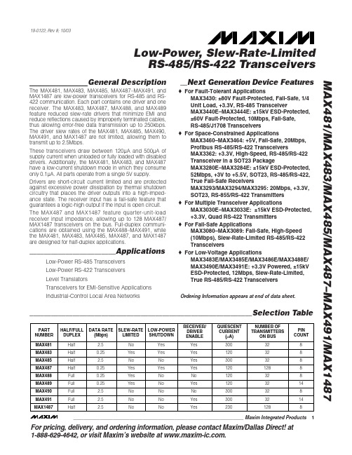
For pricing, delivery, and ordering information,please contact Maxim/Dallas Direct!at 1-888-629-4642, or visit Maxim’s website at .General DescriptionThe MAX481, MAX483, MAX485, MAX487–MAX491, and MAX1487 are low-power transceivers for RS-485 and RS-422 communication. Each part contains one driver and one receiver. The MAX483, MAX487, MAX488, and MAX489feature reduced slew-rate drivers that minimize EMI and reduce reflections caused by improperly terminated cables,thus allowing error-free data transmission up to 250kbps.The driver slew rates of the MAX481, MAX485, MAX490,MAX491, and MAX1487 are not limited, allowing them to transmit up to 2.5Mbps.These transceivers draw between 120µA and 500µA of supply current when unloaded or fully loaded with disabled drivers. Additionally, the MAX481, MAX483, and MAX487have a low-current shutdown mode in which they consume only 0.1µA. All parts operate from a single 5V supply.Drivers are short-circuit current limited and are protected against excessive power dissipation by thermal shutdown circuitry that places the driver outputs into a high-imped-ance state. The receiver input has a fail-safe feature that guarantees a logic-high output if the input is open circuit.The MAX487 and MAX1487 feature quarter-unit-load receiver input impedance, allowing up to 128 MAX487/MAX1487 transceivers on the bus. Full-duplex communi-cations are obtained using the MAX488–MAX491, while the MAX481, MAX483, MAX485, MAX487, and MAX1487are designed for half-duplex applications.________________________ApplicationsLow-Power RS-485 Transceivers Low-Power RS-422 Transceivers Level TranslatorsTransceivers for EMI-Sensitive Applications Industrial-Control Local Area Networks__Next Generation Device Features♦For Fault-Tolerant ApplicationsMAX3430: ±80V Fault-Protected, Fail-Safe, 1/4Unit Load, +3.3V, RS-485 TransceiverMAX3440E–MAX3444E: ±15kV ESD-Protected,±60V Fault-Protected, 10Mbps, Fail-Safe, RS-485/J1708 Transceivers♦For Space-Constrained ApplicationsMAX3460–MAX3464: +5V, Fail-Safe, 20Mbps,Profibus RS-485/RS-422 TransceiversMAX3362: +3.3V, High-Speed, RS-485/RS-422Transceiver in a SOT23 PackageMAX3280E–MAX3284E: ±15kV ESD-Protected,52Mbps, +3V to +5.5V, SOT23, RS-485/RS-422,True Fail-Safe ReceiversMAX3293/MAX3294/MAX3295: 20Mbps, +3.3V,SOT23, RS-855/RS-422 Transmitters ♦For Multiple Transceiver ApplicationsMAX3030E–MAX3033E: ±15kV ESD-Protected,+3.3V, Quad RS-422 Transmitters ♦For Fail-Safe ApplicationsMAX3080–MAX3089: Fail-Safe, High-Speed (10Mbps), Slew-Rate-Limited RS-485/RS-422Transceivers♦For Low-Voltage ApplicationsMAX3483E/MAX3485E/MAX3486E/MAX3488E/MAX3490E/MAX3491E: +3.3V Powered, ±15kV ESD-Protected, 12Mbps, Slew-Rate-Limited,True RS-485/RS-422 TransceiversMAX481/MAX483/MAX485/MAX487–MAX491/MAX1487Low-Power, Slew-Rate-Limited RS-485/RS-422 Transceivers______________________________________________________________Selection Table19-0122; Rev 8; 10/03Ordering Information appears at end of data sheet.M A X 481/M A X 483/M A X 485/M A X 487–M A X 491/M A X 1487Low-Power, Slew-Rate-Limited RS-485/RS-422 Transceivers 2_______________________________________________________________________________________ABSOLUTE MAXIMUM RATINGSSupply Voltage (V CC ).............................................................12V Control Input Voltage (RE , DE)...................-0.5V to (V CC + 0.5V)Driver Input Voltage (DI).............................-0.5V to (V CC + 0.5V)Driver Output Voltage (A, B)...................................-8V to +12.5V Receiver Input Voltage (A, B).................................-8V to +12.5V Receiver Output Voltage (RO).....................-0.5V to (V CC +0.5V)Continuous Power Dissipation (T A = +70°C)8-Pin Plastic DIP (derate 9.09mW/°C above +70°C)....727mW 14-Pin Plastic DIP (derate 10.00mW/°C above +70°C)..800mW 8-Pin SO (derate 5.88mW/°C above +70°C).................471mW14-Pin SO (derate 8.33mW/°C above +70°C)...............667mW 8-Pin µMAX (derate 4.1mW/°C above +70°C)..............830mW 8-Pin CERDIP (derate 8.00mW/°C above +70°C).........640mW 14-Pin CERDIP (derate 9.09mW/°C above +70°C).......727mW Operating Temperature RangesMAX4_ _C_ _/MAX1487C_ A...............................0°C to +70°C MAX4__E_ _/MAX1487E_ A.............................-40°C to +85°C MAX4__MJ_/MAX1487MJA...........................-55°C to +125°C Storage Temperature Range.............................-65°C to +160°C Lead Temperature (soldering, 10sec).............................+300°CDC ELECTRICAL CHARACTERISTICS(V CC = 5V ±5%, T A = T MIN to T MAX , unless otherwise noted.) (Notes 1, 2)Stresses beyond those listed under “Absolute Maximum Ratings” may cause permanent damage to the device. These are stress ratings only, and functional operation of the device at these or any other conditions beyond those indicated in the operational sections of the specifications is not implied. Exposure to absolute maximum rating conditions for extended periods may affect device reliability.V V IN = -7VV IN = 12V V IN = -7V V IN = 12V Input Current (A, B)I IN2V TH k Ω48-7V ≤V CM ≤12V, MAX487/MAX1487R INReceiver Input Resistance -7V ≤V CM ≤12V, all devices except MAX487/MAX1487R = 27Ω(RS-485), Figure 40.4V ≤V O ≤2.4VR = 50Ω(RS-422)I O = 4mA, V ID = -200mV I O = -4mA, V ID = 200mV V CM = 0V-7V ≤V CM ≤12V DE, DI, RE DE, DI, RE MAX487/MAX1487,DE = 0V, V CC = 0V or 5.25VDE, DI, RE R = 27Ωor 50Ω, Figure 4R = 27Ωor 50Ω, Figure 4R = 27Ωor 50Ω, Figure 4DE = 0V;V CC = 0V or 5.25V,all devices except MAX487/MAX1487CONDITIONSk Ω12µA ±1I OZRThree-State (high impedance)Output Current at ReceiverV 0.4V OL Receiver Output Low Voltage 3.5V OH Receiver Output High Voltage mV 70∆V TH Receiver Input Hysteresis V -0.20.2Receiver Differential Threshold Voltage-0.2mA 0.25mA-0.81.01.55V OD2Differential Driver Output (with load)V 2V 5V OD1Differential Driver Output (no load)µA±2I IN1Input CurrentV 0.8V IL Input Low Voltage V 2.0V IH Input High Voltage V 0.2∆V OD Change in Magnitude of Driver Common-Mode Output Voltage for Complementary Output States V 0.2∆V OD Change in Magnitude of Driver Differential Output Voltage for Complementary Output States V 3V OC Driver Common-Mode Output VoltageUNITS MINTYPMAX SYMBOL PARAMETERMAX481/MAX483/MAX485/MAX487–MAX491/MAX1487Low-Power, Slew-Rate-Limited RS-485/RS-422 Transceivers_______________________________________________________________________________________3SWITCHING CHARACTERISTICS—MAX481/MAX485, MAX490/MAX491, MAX1487(V CC = 5V ±5%, T A = T MIN to T MAX , unless otherwise noted.) (Notes 1, 2)DC ELECTRICAL CHARACTERISTICS (continued)(V CC = 5V ±5%, T A = T MIN to T MAX , unless otherwise noted.) (Notes 1, 2)ns 103060t PHLDriver Rise or Fall Time Figures 6 and 8, R DIFF = 54Ω, C L1= C L2= 100pF ns MAX490M, MAX491M MAX490C/E, MAX491C/E2090150MAX481, MAX485, MAX1487MAX490M, MAX491MMAX490C/E, MAX491C/E MAX481, MAX485, MAX1487Figures 6 and 8, R DIFF = 54Ω,C L1= C L2= 100pF MAX481 (Note 5)Figures 5 and 11, C RL = 15pF, S2 closedFigures 5 and 11, C RL = 15pF, S1 closed Figures 5 and 11, C RL = 15pF, S2 closed Figures 5 and 11, C RL = 15pF, S1 closed Figures 6 and 10, R DIFF = 54Ω,C L1= C L2= 100pFFigures 6 and 8,R DIFF = 54Ω,C L1= C L2= 100pF Figures 6 and 10,R DIFF = 54Ω,C L1= C L2= 100pF CONDITIONS ns 510t SKEW ns50200600t SHDNTime to ShutdownMbps 2.5f MAX Maximum Data Rate ns 2050t HZ Receiver Disable Time from High ns 103060t PLH 2050t LZ Receiver Disable Time from Low ns 2050t ZH Driver Input to Output Receiver Enable to Output High ns 2050t ZL Receiver Enable to Output Low 2090200ns ns 134070t HZ t SKD Driver Disable Time from High |t PLH - t PHL |DifferentialReceiver Skewns 4070t LZ Driver Disable Time from Low ns 4070t ZL Driver Enable to Output Low 31540ns51525ns 31540t R , t F 2090200Driver Output Skew to Output t PLH , t PHL Receiver Input to Output4070t ZH Driver Enable to Output High UNITS MIN TYP MAX SYMBOL PARAMETERFigures 7 and 9, C L = 100pF, S2 closed Figures 7 and 9, C L = 100pF, S1 closed Figures 7 and 9, C L = 15pF, S1 closed Figures 7 and 9, C L = 15pF, S2 closedM A X 481/M A X 483/M A X 485/M A X 487–M A X 491/M A X 1487Low-Power, Slew-Rate-Limited RS-485/RS-422 Transceivers 4_______________________________________________________________________________________SWITCHING CHARACTERISTICS—MAX483, MAX487/MAX488/MAX489(V CC = 5V ±5%, T A = T MIN to T MAX , unless otherwise noted.) (Notes 1, 2)SWITCHING CHARACTERISTICS—MAX481/MAX485, MAX490/MAX491, MAX1487 (continued)(V CC = 5V ±5%, T A = T MIN to T MAX , unless otherwise noted.) (Notes 1, 2)3001000Figures 7 and 9, C L = 100pF, S2 closed Figures 7 and 9, C L = 100pF, S1 closed Figures 5 and 11, C L = 15pF, S2 closed,A - B = 2VCONDITIONSns 40100t ZH(SHDN)Driver Enable from Shutdown toOutput High (MAX481)nsFigures 5 and 11, C L = 15pF, S1 closed,B - A = 2Vt ZL(SHDN)Receiver Enable from Shutdownto Output Low (MAX481)ns 40100t ZL(SHDN)Driver Enable from Shutdown toOutput Low (MAX481)ns 3001000t ZH(SHDN)Receiver Enable from Shutdownto Output High (MAX481)UNITS MINTYP MAX SYMBOLPARAMETERt PLH t SKEW Figures 6 and 8, R DIFF = 54Ω,C L1= C L2= 100pFt PHL Figures 6 and 8, R DIFF = 54Ω,C L1= C L2= 100pFDriver Input to Output Driver Output Skew to Output ns 100800ns ns 2000MAX483/MAX487, Figures 7 and 9,C L = 100pF, S2 closedt ZH(SHDN)Driver Enable from Shutdown to Output High2502000ns2500MAX483/MAX487, Figures 5 and 11,C L = 15pF, S1 closedt ZL(SHDN)Receiver Enable from Shutdown to Output Lowns 2500MAX483/MAX487, Figures 5 and 11,C L = 15pF, S2 closedt ZH(SHDN)Receiver Enable from Shutdown to Output Highns 2000MAX483/MAX487, Figures 7 and 9,C L = 100pF, S1 closedt ZL(SHDN)Driver Enable from Shutdown to Output Lowns 50200600MAX483/MAX487 (Note 5) t SHDN Time to Shutdownt PHL t PLH , t PHL < 50% of data period Figures 5 and 11, C RL = 15pF, S2 closed Figures 5 and 11, C RL = 15pF, S1 closed Figures 5 and 11, C RL = 15pF, S2 closed Figures 5 and 11, C RL = 15pF, S1 closed Figures 7 and 9, C L = 15pF, S2 closed Figures 6 and 10, R DIFF = 54Ω,C L1= C L2= 100pFFigures 7 and 9, C L = 15pF, S1 closed Figures 7 and 9, C L = 100pF, S1 closed Figures 7 and 9, C L = 100pF, S2 closed CONDITIONSkbps 250f MAX 2508002000Maximum Data Rate ns 2050t HZ Receiver Disable Time from High ns 25080020002050t LZ Receiver Disable Time from Low ns 2050t ZH Receiver Enable to Output High ns 2050t ZL Receiver Enable to Output Low ns ns 1003003000t HZ t SKD Driver Disable Time from High I t PLH - t PHL I DifferentialReceiver SkewFigures 6 and 10, R DIFF = 54Ω,C L1= C L2= 100pFns 3003000t LZ Driver Disable Time from Low ns 2502000t ZL Driver Enable to Output Low ns Figures 6 and 8, R DIFF = 54Ω,C L1= C L2= 100pFns 2502000t R , t F 2502000Driver Rise or Fall Time ns t PLH Receiver Input to Output2502000t ZH Driver Enable to Output High UNITS MIN TYP MAX SYMBOL PARAMETERMAX481/MAX483/MAX485/MAX487–MAX491/MAX1487Low-Power, Slew-Rate-Limited RS-485/RS-422 Transceivers_______________________________________________________________________________________530002.5OUTPUT CURRENT vs.RECEIVER OUTPUT LOW VOLTAGE525M A X 481-01OUTPUT LOW VOLTAGE (V)O U T P U T C U R R E N T (m A )1.515100.51.02.0203540450.90.1-50-252575RECEIVER OUTPUT LOW VOLTAGE vs.TEMPERATURE0.30.7TEMPERATURE (°C)O U T P U TL O W V O L T A G E (V )500.50.80.20.60.40100125-20-41.5 2.0 3.0 5.0OUTPUT CURRENT vs.RECEIVER OUTPUT HIGH VOLTAGE-8-16M A X 481-02OUTPUT HIGH VOLTAGE (V)O U T P U T C U R R E N T (m A )2.5 4.0-12-18-6-14-10-203.54.5 4.83.2-50-252575RECEIVER OUTPUT HIGH VOLTAGE vs.TEMPERATURE3.64.4TEMPERATURE (°C)O U T P UT H I G H V O L T A G E (V )0504.04.63.44.23.83.01001259000 1.0 3.0 4.5DRIVER OUTPUT CURRENT vs.DIFFERENTIAL OUTPUT VOLTAGE1070M A X 481-05DIFFERENTIAL OUTPUT VOLTAGE (V)O U T P U T C U R R E N T (m A )2.0 4.05030806040200.5 1.5 2.53.5 2.31.5-50-2525125DRIVER DIFFERENTIAL OUTPUT VOLTAGEvs. TEMPERATURE1.72.1TEMPERATURE (°C)D I F FE R E N T I A L O U T P U T V O L T A G E (V )751.92.21.62.01.8100502.4__________________________________________Typical Operating Characteristics(V CC = 5V, T A = +25°C, unless otherwise noted.)NOTES FOR ELECTRICAL/SWITCHING CHARACTERISTICSNote 1:All currents into device pins are positive; all currents out of device pins are negative. All voltages are referenced to deviceground unless otherwise specified.Note 2:All typical specifications are given for V CC = 5V and T A = +25°C.Note 3:Supply current specification is valid for loaded transmitters when DE = 0V.Note 4:Applies to peak current. See Typical Operating Characteristics.Note 5:The MAX481/MAX483/MAX487 are put into shutdown by bringing RE high and DE low. If the inputs are in this state for lessthan 50ns, the parts are guaranteed not to enter shutdown. If the inputs are in this state for at least 600ns, the parts are guaranteed to have entered shutdown. See Low-Power Shutdown Mode section.M A X 481/M A X 483/M A X 485/M A X 487–M A X 491/M A X 1487Low-Power, Slew-Rate-Limited RS-485/RS-422 Transceivers 6___________________________________________________________________________________________________________________Typical Operating Characteristics (continued)(V CC = 5V, T A = +25°C, unless otherwise noted.)120008OUTPUT CURRENT vs.DRIVER OUTPUT LOW VOLTAGE20100M A X 481-07OUTPUT LOW VOLTAGE (V)O U T P U T C U R R E N T (m A )6604024801012140-1200-7-5-15OUTPUT CURRENT vs.DRIVER OUTPUT HIGH VOLTAGE-20-80M A X 481-08OUTPUT HIGH VOLTAGE (V)O U T P U T C U R R E N T (m A )-31-603-6-4-2024-100-40100-40-60-2040100120MAX1487SUPPLY CURRENT vs. TEMPERATURE300TEMPERATURE (°C)S U P P L Y C U R R E N T (µA )20608050020060040000140100-50-2550100MAX481/MAX485/MAX490/MAX491SUPPLY CURRENT vs. TEMPERATURE300TEMPERATURE (°C)S U P P L Y C U R R E N T (µA )257550020060040000125100-50-2550100MAX483/MAX487–MAX489SUPPLY CURRENT vs. TEMPERATURE300TEMPERATURE (°C)S U P P L Y C U R R E N T (µA )257550020060040000125MAX481/MAX483/MAX485/MAX487–MAX491/MAX1487Low-Power, Slew-Rate-Limited RS-485/RS-422 Transceivers_______________________________________________________________________________________7______________________________________________________________Pin DescriptionFigure 1. MAX481/MAX483/MAX485/MAX487/MAX1487 Pin Configuration and Typical Operating CircuitM A X 481/M A X 483/M A X 485/M A X 487–M A X 491/M A X 1487__________Applications InformationThe MAX481/MAX483/MAX485/MAX487–MAX491 and MAX1487 are low-power transceivers for RS-485 and RS-422 communications. The MAX481, MAX485, MAX490,MAX491, and MAX1487 can transmit and receive at data rates up to 2.5Mbps, while the MAX483, MAX487,MAX488, and MAX489 are specified for data rates up to 250kbps. The MAX488–MAX491 are full-duplex trans-ceivers while the MAX481, MAX483, MAX485, MAX487,and MAX1487 are half-duplex. In addition, Driver Enable (DE) and Receiver Enable (RE) pins are included on the MAX481, MAX483, MAX485, MAX487, MAX489,MAX491, and MAX1487. When disabled, the driver and receiver outputs are high impedance.MAX487/MAX1487:128 Transceivers on the BusThe 48k Ω, 1/4-unit-load receiver input impedance of the MAX487 and MAX1487 allows up to 128 transceivers on a bus, compared to the 1-unit load (12k Ωinput impedance) of standard RS-485 drivers (32 trans-ceivers maximum). Any combination of MAX487/MAX1487 and other RS-485 transceivers with a total of 32 unit loads or less can be put on the bus. The MAX481/MAX483/MAX485 and MAX488–MAX491 have standard 12k ΩReceiver Input impedance.Low-Power, Slew-Rate-Limited RS-485/RS-422 Transceivers 8_______________________________________________________________________________________Figure 2. MAX488/MAX490 Pin Configuration and Typical Operating CircuitFigure 3. MAX489/MAX491 Pin Configuration and Typical Operating CircuitMAX483/MAX487/MAX488/MAX489:Reduced EMI and ReflectionsThe MAX483 and MAX487–MAX489 are slew-rate limit-ed, minimizing EMI and reducing reflections caused by improperly terminated cables. Figure 12 shows the dri-ver output waveform and its Fourier analysis of a 150kHz signal transmitted by a MAX481, MAX485,MAX490, MAX491, or MAX1487. High-frequency har-monics with large amplitudes are evident. Figure 13shows the same information displayed for a MAX483,MAX487, MAX488, or MAX489 transmitting under the same conditions. Figure 13’s high-frequency harmonics have much lower amplitudes, and the potential for EMI is significantly reduced.MAX481/MAX483/MAX485/MAX487–MAX491/MAX1487Low-Power, Slew-Rate-Limited RS-485/RS-422 Transceivers_______________________________________________________________________________________9_________________________________________________________________Test CircuitsFigure 4. Driver DC Test Load Figure 5. Receiver Timing Test LoadFigure 6. Driver/Receiver Timing Test Circuit Figure 7. Driver Timing Test LoadM A X 481/M A X 483/M A X 485/M A X 487–M A X 491/M A X 1487Low-Power, Slew-Rate-Limited RS-485/RS-422 Transceivers 10_______________________________________________________Switching Waveforms_________________Function Tables (MAX481/MAX483/MAX485/MAX487/MAX1487)Figure 8. Driver Propagation DelaysFigure 9. Driver Enable and Disable Times (except MAX488 and MAX490)Figure 10. Receiver Propagation DelaysFigure 11. Receiver Enable and Disable Times (except MAX488and MAX490)Table 1. TransmittingTable 2. ReceivingLow-Power Shutdown Mode (MAX481/MAX483/MAX487)A low-power shutdown mode is initiated by bringing both RE high and DE low. The devices will not shut down unless both the driver and receiver are disabled.In shutdown, the devices typically draw only 0.1µA of supply current.RE and DE may be driven simultaneously; the parts are guaranteed not to enter shutdown if RE is high and DE is low for less than 50ns. If the inputs are in this state for at least 600ns, the parts are guaranteed to enter shutdown.For the MAX481, MAX483, and MAX487, the t ZH and t ZL enable times assume the part was not in the low-power shutdown state (the MAX485/MAX488–MAX491and MAX1487 can not be shut down). The t ZH(SHDN)and t ZL(SHDN)enable times assume the parts were shut down (see Electrical Characteristics ).It takes the drivers and receivers longer to become enabled from the low-power shutdown state (t ZH(SHDN ), t ZL(SHDN)) than from the operating mode (t ZH , t ZL ). (The parts are in operating mode if the –R —E –,DE inputs equal a logical 0,1 or 1,1 or 0, 0.)Driver Output ProtectionExcessive output current and power dissipation caused by faults or by bus contention are prevented by two mechanisms. A foldback current limit on the output stage provides immediate protection against short cir-cuits over the whole common-mode voltage range (see Typical Operating Characteristics ). In addition, a ther-mal shutdown circuit forces the driver outputs into a high-impedance state if the die temperature rises excessively.Propagation DelayMany digital encoding schemes depend on the differ-ence between the driver and receiver propagation delay times. Typical propagation delays are shown in Figures 15–18 using Figure 14’s test circuit.The difference in receiver delay times, | t PLH - t PHL |, is typically under 13ns for the MAX481, MAX485,MAX490, MAX491, and MAX1487 and is typically less than 100ns for the MAX483 and MAX487–MAX489.The driver skew times are typically 5ns (10ns max) for the MAX481, MAX485, MAX490, MAX491, and MAX1487, and are typically 100ns (800ns max) for the MAX483 and MAX487–MAX489.MAX481/MAX483/MAX485/MAX487–MAX491/MAX1487Low-Power, Slew-Rate-Limited RS-485/RS-422 Transceivers______________________________________________________________________________________1110dB/div0Hz5MHz500kHz/div10dB/div0Hz5MHz500kHz/divFigure 12. Driver Output Waveform and FFT Plot of MAX481/MAX485/MAX490/MAX491/MAX1487 Transmitting a 150kHz SignalFigure 13. Driver Output Waveform and FFT Plot of MAX483/MAX487–MAX489 Transmitting a 150kHz SignalM A X 481/M A X 483/M A X 485/M A X 487–M A X 491/M A X 1487Low-Power, Slew-Rate-Limited RS-485/RS-422 Transceivers 12______________________________________________________________________________________V CC = 5V T A = +25°CV CC = 5V T A = +25°CV CC = 5V T A = +25°CV CC = 5V T A = +25°CFigure 14. Receiver Propagation Delay Test CircuitFigure 15. MAX481/MAX485/MAX490/MAX491/MAX1487Receiver t PHLFigure 16. MAX481/MAX485/MAX490/MAX491/MAX1487Receiver t PLHPHL Figure 18. MAX483, MAX487–MAX489 Receiver t PLHLine Length vs. Data RateThe RS-485/RS-422 standard covers line lengths up to 4000 feet. For line lengths greater than 4000 feet, see Figure 23.Figures 19 and 20 show the system differential voltage for the parts driving 4000 feet of 26AWG twisted-pair wire at 110kHz into 120Ωloads.Typical ApplicationsThe MAX481, MAX483, MAX485, MAX487–MAX491, and MAX1487 transceivers are designed for bidirectional data communications on multipoint bus transmission lines.Figures 21 and 22 show typical network applications circuits. These parts can also be used as line repeaters, with cable lengths longer than 4000 feet, as shown in Figure 23.To minimize reflections, the line should be terminated at both ends in its characteristic impedance, and stub lengths off the main line should be kept as short as possi-ble. The slew-rate-limited MAX483 and MAX487–MAX489are more tolerant of imperfect termination.MAX481/MAX483/MAX485/MAX487–MAX491/MAX1487Low-Power, Slew-Rate-Limited RS-485/RS-422 Transceivers______________________________________________________________________________________13DIV Y -V ZRO5V 0V1V0V -1V5V 0V2µs/divFigure 19. MAX481/MAX485/MAX490/MAX491/MAX1487 System Differential Voltage at 110kHz Driving 4000ft of Cable Figure 20. MAX483, MAX487–MAX489 System Differential Voltage at 110kHz Driving 4000ft of CableFigure 21. MAX481/MAX483/MAX485/MAX487/MAX1487 Typical Half-Duplex RS-485 NetworkM A X 481/M A X 483/M A X 485/M A X 487–M A X 491/M A X 1487Low-Power, Slew-Rate-Limited RS-485/RS-422 Transceivers 14______________________________________________________________________________________Figure 22. MAX488–MAX491 Full-Duplex RS-485 NetworkFigure 23. Line Repeater for MAX488–MAX491Isolated RS-485For isolated RS-485 applications, see the MAX253 and MAX1480 data sheets.MAX481/MAX483/MAX485/MAX487–MAX491/MAX1487Low-Power, Slew-Rate-Limited RS-485/RS-422 Transceivers______________________________________________________________________________________15_______________Ordering Information_________________Chip TopographiesMAX481/MAX483/MAX485/MAX487/MAX1487N.C. RO 0.054"(1.372mm)0.080"(2.032mm)DE DIGND B N.C.V CCARE * Contact factory for dice specifications.__Ordering Information (continued)M A X 481/M A X 483/M A X 485/M A X 487–M A X 491/M A X 1487Low-Power, Slew-Rate-Limited RS-485/RS-422 Transceivers 16______________________________________________________________________________________TRANSISTOR COUNT: 248SUBSTRATE CONNECTED TO GNDMAX488/MAX490B RO 0.054"(1.372mm)0.080"(2.032mm)N.C. DIGND Z A V CCYN.C._____________________________________________Chip Topographies (continued)MAX489/MAX491B RO 0.054"(1.372mm)0.080"(2.032mm)DE DIGND Z A V CCYREMAX481/MAX483/MAX485/MAX487–MAX491/MAX1487Low-Power, Slew-Rate-Limited RS-485/RS-422 Transceivers______________________________________________________________________________________17Package Information(The package drawing(s) in this data sheet may not reflect the most current specifications. For the latest package outline information go to /packages .)S O I C N .E P SM A X 481/M A X 483/M A X 485/M A X 487–M A X 491/M A X 1487Low-Power, Slew-Rate-Limited RS-485/RS-422 Transceivers 18______________________________________________________________________________________Package Information (continued)(The package drawing(s) in this data sheet may not reflect the most current specifications. For the latest package outline information go to /packages .)MAX481/MAX483/MAX485/MAX487–MAX491Low-Power, Slew-Rate-Limited RS-485/RS-422 TransceiversMaxim cannot assume responsibility for use of any circuitry other than circuitry entirely embodied in a Maxim product. No circuit patent licenses are implied. Maxim reserves the right to change the circuitry and specifications without notice at any time.Maxim Integrated Products, 120 San Gabriel Drive, Sunnyvale, CA 94086 408-737-7600 ____________________19©2003 Maxim Integrated ProductsPrinted USAis a registered trademark of Maxim Integrated Products.M A X 481/M A X 483/M A X 485/M A X 487–M A X 491/M A X 1487P D I P N .E PSPackage Information (continued)(The package drawing(s) in this data sheet may not reflect the most current specifications. For the latest package outline information go to /packages .)。
- 1、下载文档前请自行甄别文档内容的完整性,平台不提供额外的编辑、内容补充、找答案等附加服务。
- 2、"仅部分预览"的文档,不可在线预览部分如存在完整性等问题,可反馈申请退款(可完整预览的文档不适用该条件!)。
- 3、如文档侵犯您的权益,请联系客服反馈,我们会尽快为您处理(人工客服工作时间:9:00-18:30)。
MAX5878
42 41 40 39 38 37 36 35
AVDD1.8
GND
GND
GND
GND
GND
OUTQN
OUTQP
OUTIN
DACREF
AVDD3.3
AVDD3.3
OUTIP
AVDD3.3
AVDD3.3
GND
QFN
________________________________________________________________ Maxim Integrated Products
Note 1: Thermal resistors based on a multilayer board with 4 x 4 via array in exposed paddle area.
Stresses beyond those listed under “Absolute Maximum Ratings” may cause permanent damage to the device. These are stress ratings only, and functional operation of the device at these or any other conditions beyond those indicated in the operational sections of the specifications is not implied. Exposure to absolute maximum rating conditions for extended periods may affect device reliability.
The MAX5878 is an advanced 16-bit, 250Msps, dual digital-to-analog converter (DAC). This DAC meets the demanding performance requirements of signal synthesis applications found in wireless base stations and other communications applications. Operating from +3.3V and +1.8V supplies, this dual DAC offers exceptional dynamic performance such as 76dBc spurious-free dynamic range (SFDR) at fOUT = 16MHz and supports update rates of 250Msps, with a power dissipation of only 296mW. The MAX5878 utilizes a current-steering architecture that supports a 2mA to 20mA full-scale output current range, and allows a 0.1VP-P to 1VP-P differential output voltage swing. The device features an integrated +1.2V bandgap reference and control amplifier to ensure high-accuracy and low-noise performance. A separate reference input (REFIO) allows for the use of an external reference source for optimum flexibility and improved gain accuracy. The clock inputs of the MAX5878 accept both LVDS and LVPECL-compatible voltage levels. The device features an interleaved data input that allows a single LVDS bus to support both DACs. The MAX5878 is available in a 68-pin QFN package with an exposed paddle (EP) and is specified for the extended temperature range (-40°C to +85°C). Refer to the MAX5876 and MAX5877 data sheets for pin-compatible 12-bit and 14-bit versions of the MAX5878, respectively. Refer to the MAX5875 data sheet for a CMOS-compatible version of the MAX5878.
1 2 3 4 5 6 7 8 9 10 11 12 13 14 15 16 17 18 19 20 21 22 23 24 25 26 27 28 29 30 31 32 33 34
B12P B13N B13P B14N B14P B15N B15P SELIQN SELIQP XORP XORN PD TORB CLKP CLKN GND AVCLK
元器件交易网
16-Bit, 250Msps, High-Dynamic-Performance, Dual DAC with LVDS Inputs MAX5878
ABSOLUTE MAXIMUM RATINGS
AVDD1.8, DVDD1.8 to GND, DACREF...................-0.3V to +2.16V AVDD3.3, DVDD3.3, AVCLK to GND, DACREF ........-0.3V to +3.9V REFIO, FSADJ to GND, DACREF..................................-0.3V to (AVDD3.3 + 0.3V) OUTIP, OUTIN, OUTQP, OUTQN to GND, DACREF..................-1V to (AVDD3.3 + 0.3V) CLKP, CLKN to GND, DACREF.............-0.3V to (AVCLK + 0.3V) B15P/B15N–B0P/B0N, XORN, XORP, SELIQN, SELIQP to GND, DACREF ..................-0.3V to (DVDD1.8 + 0.3V) TORB, PD to GND, DACREF ..............-0.3V to (DVDD3.3 + 0.3V) Continuous Power Dissipation (TA = +70°C) 68-Pin QFN-EP (derate 41.7mW/°C above +70°C) (Note 1) ............3333.3mW Thermal Resistance θJA (Note 1)...................................+24°C/W Operating Temperature Range ......................... -40°C to +85°C Junction Temperature .................................................... +150°C Storage Temperature Range ........................... -60°C to +150°C Lead Temperature (soldering, 10s) ............................... +300°C
*EP = Exposed pad. + = Lead-free package. D = Dry pack.
Pin Configuration
B10N B11N B12N B10P B11P
B5N
B6N
B7N
B8N
B9N
B4P
B5P
B6P
B7P
B8P
Base Stations: Single/Multicarrier UMTS, CDMA, GSM Communications: Fixed Broadband Wireless Access, Point-to-Point Microwave Direct Digital Synthesis (DDS) Cable Modem Termination Systems (CMTS) Automated Test Equipment (ATE) Instrumentation
Features
♦ 250Msps Output Update Rate ♦ Noise Spectral Density = -164dBFS/Hz at fOUT = 16MHz ♦ Excellent SFDR and IMD Performance SFDR = 76dBc at fOUT = 16MHz (to Nyquist) SFDR = 71dBc at fOUT = 80MHz (to Nyquist) IMD = -90dBc at fOUT = 10MHz IMD = -72dBc at fOUT = 80MHz ♦ ACLR = 75dB at fOUT = 61MHz ♦ 2mA to 20mA Full-Scale Output Current ♦ LVDS-Compatible Digital and Clock Inputs ♦ On-Chip +1.20V Bandgap Reference ♦ Low 296mW Power Dissipation ♦ Compact 68 QFN-EP Package (10mm x 10mm) ♦ Evaluation Kit Available (MAX5878EVKIT)