SBC556中文资料
BC560ABU中文资料

BC556/557/558/559/560PNP Epitaxial Silicon TransistorAbsolute Maximum Ratings T a =25°C unless otherwise notedElectrical Characteristics T a =25°C unless otherwise notedh FE ClassificationSymbol ParameterValue Units V CBOCollector-Base Voltage: BC556 : BC557/560: BC558/559 -80-50-30V V V V CEOCollector-Emitter Voltage: BC556 : BC557/560: BC558/559-65-45-30V V V V EBO Emitter-Base Voltage -5V I C Collector Current (DC)-100mA P C Collector Power Dissipation 500mW T J Junction Temperature 150°C T STGStorage Temperature-65 ~ 150°CSymbol ParameterTest ConditionMin.Typ.Max.Units I CBO Collector Cut-off Current V CB = -30V, I E =0-15nAh FE DC Current GainV CE = -5V, I C =2mA 110800V CE (sat)Collector-Emitter Saturation Voltage I C = -10mA, I B = -0.5mA I C = -100mA, I B = -5mA -90-250-300-650mV mV V BE (sat)Collector-Base Saturation Voltage I C = -10mA, I B = -0.5mA I C = -100mA, I B = -5mA -700-900mV mV V BE (on)Base-Emitter On VoltageV CE = -5V, I C = -2mA V CE = -5V, I C = -10mA-600-660-750-800mV mV f T Current Gain Bandwidth Product V CE = -5V, I C = -10mA, f=10MHz 150MHz C ob Output CapacitanceV CB = -10V, I E =0, f=1MHz 6pF NFNoise Figure : BC556/557/558: BC559/560: BC559: BC560V CE = -5V, I C = -200µA f=1KHz, R G =2K ΩV CE = -5V, I C = -200µAR G =2K Ω, f=30~15000MHz211.21.210442dB dB dB dB ClassificationA B C h FE110 ~ 220200 ~ 450420 ~ 800BC556/557/558/559/560Switching and Amplifier•High Voltage: BC556, V CEO = -65V •Low Noise: BC559, BC560•Complement to BC546 ... BC 5501. Collector2. Base3. EmitterTO-921BC556/557/558/559/560BC556/557/558/559/560TRADEMARKSThe following are registered and unregistered trademarks Fairchild Semiconductor owns or is authorized to use and is not intended to be an exhaustive list of all such trademarks.DISCLAIMERFAIRCHILD SEMICONDUCTOR RESERVES THE RIGHT TO MAKE CHANGES WITHOUT FURTHER NOTICE TO ANY PRODUCTS HEREIN TO IMPROVE RELIABILITY, FUNCTION OR DESIGN. FAIRCHILD DOES NOT ASSUME ANY LIABILITY ARISING OUT OF THE APPLICATION OR USE OF ANY PRODUCT OR CIRCUIT DESCRIBED HEREIN;NEITHER DOES IT CONVEY ANY LICENSE UNDER ITS PATENT RIGHTS, NOR THE RIGHTS OF OTHERS.LIFE SUPPORT POLICYFAIRCHILD’S PRODUCTS ARE NOT AUTHORIZED FOR USE AS CRITICAL COMPONENTS IN LIFE SUPPORT DEVICES OR SYSTEMS WITHOUT THE EXPRESS WRITTEN APPROVAL OF FAIRCHILD SEMICONDUCTOR CORPORATION.As used herein:1. Life support devices or systems are devices or systems which, (a) are intended for surgical implant into the body,or (b) support or sustain life, or (c) whose failure to perform when properly used in accordance with instructions for use provided in the labeling, can be reasonably expected to result in significant injury to the user.2. A critical component is any component of a life support device or system whose failure to perform can be reasonably expected to cause the failure of the life support device or system, or to affect its safety or effectiveness.PRODUCT STATUS DEFINITIONS Definition of TermsDatasheet Identification Product Status DefinitionAdvance InformationFormative or In Design This datasheet contains the design specifications for product development. Specifications may change in any manner without notice.PreliminaryFirst ProductionThis datasheet contains preliminary data, andsupplementary data will be published at a later date.Fairchild Semiconductor reserves the right to make changes at any time without notice in order to improve design.No Identification Needed Full ProductionThis datasheet contains final specifications. Fairchild Semiconductor reserves the right to make changes at any time without notice in order to improve design.Obsolete Not In ProductionThis datasheet contains specifications on a product that has been discontinued by Fairchild semiconductor.The datasheet is printed for reference information only.FACT™FACT Quiet series™FAST ®FASTr™FRFET™GlobalOptoisolator™GTO™HiSeC™I 2C™ImpliedDisconnect™ISOPLANAR™LittleFET™MicroFET™MicroPak™MICROWIRE™MSX™MSXPro™OCX™OCXPro™OPTOLOGIC ®OPTOPLANAR™PACMAN™POP™Power247™PowerTrench ®QFET™QS™QT Optoelectronics™Quiet Series™RapidConfigure™RapidConnect™SILENT SWITCHER ®SMART START™SPM™Stealth™SuperSOT™-3SuperSOT™-6SuperSOT™-8SyncFET™TinyLogic™TruTranslation™UHC™UltraFET ®VCX™ACEx™ActiveArray™Bottomless™CoolFET™CROSSVOLT ™DOME™EcoSPARK™E 2CMOS™EnSigna™Across the board. Around the world.™The Power Franchise™Programmable Active Droop™。
STBN556中文资料

Symbol
PPK PD TJ, TSTG
Value
Minimum 1500 5.0 - 55 to + 150
Unit
W W °C
Note :
(1) Non-repetitive Current pulse, per Fig. 2 and derated above Ta = 25 °C per Fig. 1 (2) Mounted on copper Lead area at 5.0 mm2 ( 0.013 mm thick ).
Dimensions in inches and (millimeter)
DEVICES FOR UNIPOLAR APPLICATIONS
For Uni-directional altered the third letter of type from "B" to be "U". Electrical characteristics apply in both directions
0.121(3.07) 0.115(2.92) 0.2 45(6.22) 0.2 20(5.59) 0.103(2.62 ) 0.079(2.00 ) 0.012(0.305) 0.006(0.152)
MECHANICAL DATA
* Case : SMC Molded plastic * Epoxy : UL94V-O rate flame retardant * Lead : Lead Formed for Surface Mount * Polarity : Color band denotes cathode end except Bipolar. * Mounting position : Any * Weight : 0.21 grams
pmc5565产品使用说明
pmc5565产品使用说明
产品概述
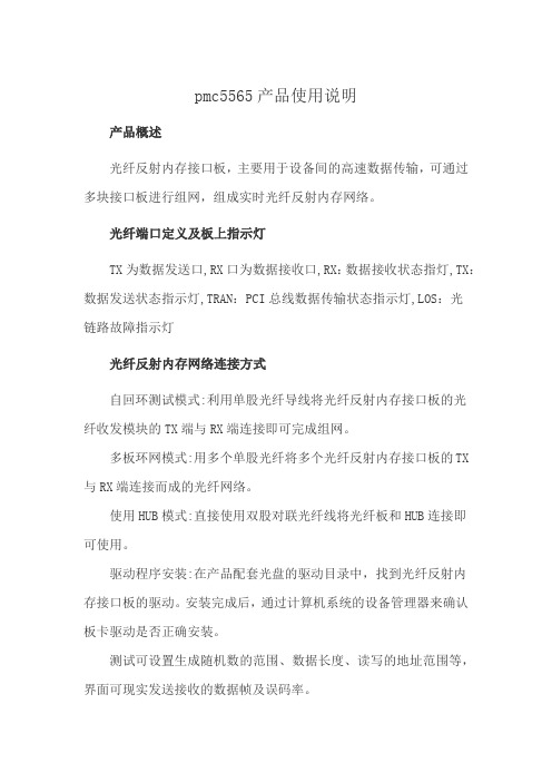
光纤反射内存接口板,主要用于设备间的高速数据传输,可通过多块接口板进行组网,组成实时光纤反射内存网络。
光纤端口定义及板上指示灯
TX为数据发送口,RX口为数据接收口,RX:数据接收状态指灯,TX:数据发送状态指示灯,TRAN:PCI总线数据传输状态指示灯,LOS:光
链路故障指示灯
光纤反射内存网络连接方式
自回环测试模式:利用单股光纤导线将光纤反射内存接口板的光
纤收发模块的TX端与RX端连接即可完成组网。
多板环网模式:用多个单股光纤将多个光纤反射内存接口板的TX 与RX端连接而成的光纤网络。
使用HUB模式:直接使用双股对联光纤线将光纤板和HUB连接即
可使用。
驱动程序安装:在产品配套光盘的驱动目录中,找到光纤反射内
存接口板的驱动。
安装完成后,通过计算机系统的设备管理器来确认板卡驱动是否正确安装。
测试可设置生成随机数的范围、数据长度、读写的地址范围等,界面可现实发送接收的数据帧及误码率。
MPC566MZP56中文资料
MOTOROLA
MPC565PB/D Rev. 2, 5 December 2001
SEMICONDUCTOR
PRODUCT BRIEF
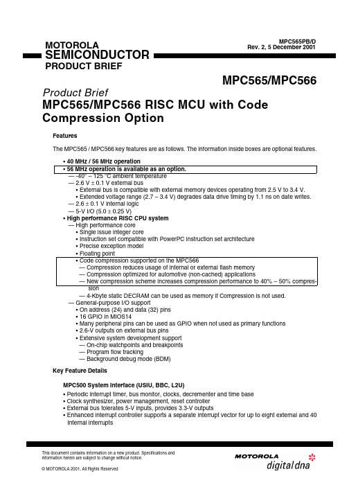
MPC565/MPC566
Product Brief
MPC565/MPC566 RISC MCU with Code Compression Option
MPC565/MPC566ຫໍສະໝຸດ PRODUCT BRIEF
MOTOROLA 2
元器件交易网
22-Channel MIOS timer (MIOS14) • Six modulus counter sub-module (MCSM) — Four additional MCSM submodules compared to MIOS1 • 10 double action sub-module (DASM). • 12 dedicated PWM sub-modules (PWMSM) — Four additional PWM submodules compared to MIOS1 (shared with MIOS GPIO pins) • Real-time clock sub-module (MRTCSM) provides low power clock/counter — Requires external 32-KHz crystal — Uses four pins: two for 32-KHz crystal, two for power/ground. Two Queued Analog-to-Digital Converter Modules (QADC64E_A, QADC64E_B) • AMUXes providing a total of 40 analog channels. • 40 total input channels on the two modules with internal multiplexing (AMUXes) • Each QADC64E can see all 40 input channels • 10 bit A/D converter with internal sample/hold • Typical conversion time is 4 µs (250-Kbyte samples/sec) • Two conversion command queues of variable length • Automated queue modes initiated by: — External edge trigger/level gate — Software command — Periodic/interval timer, assignable to both queue 1 and 2 • 64 result registers in each QADC64E module • Conversions alternate reference (ALTREF) pin. This pin can be connected to a different reference voltage • Output data is right or left justified, signed or unsigned Message Data Link Controller (DLCMD2) Module • Two pins muxed with QSMCM_B pins. Muxing controlled by QSMCM_B PCS3 pin assignment register • SAE J1850 Class B data communications network interface compatible and ISO compatible for low-speed (< 125 Kbps) serial data communications in automotive applications • 10.4 Kbps variable pulse width (VPW) bit format • Digital noise filter, collision detection • Hardware cyclical redundancy check (CRC) generation and checking • Block mode receive and transmit supported • 4X receive mode supported (41.6 Kbps) • Digital loopback mode • In-frame response (IFR) types 0, 1, 2, and 3 supported • Dedicated register for symbol timing adjustments • Inter-module bus 3 (IMB3) slave interface • Power-saving IMB3 stop mode with automatic wakeup on network activity • Power-saving IMB3 CLOCKDIS mode • Debug mode available through IMB3 FREEZE signal or user controllable SOFT_FRZ bit • Polling and IMB3 interrupt generation with vector lookup available Three TouCAN™ Modules (TOUCAN_A, TOUCAN_B, TOUCAN_C) • 16 message buffers each, programmable I/O modes • Maskable interrupts • Programmable loop-back for self test operation • Independent of the transmission medium (external transceiver is assumed) • Open network architecture, multimaster concept • High immunity to EMI • Short latency time for high-priority messages • Low power sleep mode, with programmable wake up on bus activity
电力防御SB双窄五千安坚电流保护器说明书

Eaton SPN65A4CEAXX2CEaton Power Defense SB, Double Narrow, 5000 A, 65 kA, 4-Pole,Drawout w/ MR2, PXR20LSIG, 65A4CEAXX2CGeneral specificationsEaton Magnum low voltage power circuitbreakerSPN65A4CEAXX2C78668973939316.3 in16.8 in32.4 in177 lbSABA Listed CCC Marked CE Marked NEMA Compliant Lloyd's Register Certified UL ListedCSA CertifiedANSIKEMA CertifiedDNV GL CertifiedABS CertifiedProduct Name Catalog NumberUPCProduct Length/Depth Product Height Product Width Product Weight Compliances Certifications5000 A UL 891Double narrow Four-pole Power Defense SBMR2UL 891Double narrow Magnum PXR20Drawout Four-pole5000 A 600 VACDrawout 65 kA65 kA5000 A5000 A 600 VACZone selective interlocking application paper Magnum circuit breakers with Power Xpert Release trip units product aid Amperage Rating Application Frame Number of poles TypeAccessories Application Frame Series Trip Type Mounting Method Number of poles Rated uninterrupted current (Iu)Voltage rating Mounting Method Interrupt rating Interrupt rating Amperage Rating Rated uninterrupted current (Iu)Voltage rating Application notesBrochuresCatalogsEaton Corporation plc Eaton House30 Pembroke Road Dublin 4, Ireland © 2023 Eaton. All Rights Reserved. Eaton is a registered trademark.All other trademarks areproperty of their respectiveowners./socialmediaSelevctive coordination application paper - IA0120000E3Magnum PXR and PD-SB standard and narrow frame UL Certificate of ComplianceMagnum PXR and PD-SB double and double narrow frame UL Certificate of CompliancePower Xpert Release trip unit for Magnum PXR circuit breakers PXR 20/25 user manualMicrosoft Word - Power Xpert Protection Manager Quick Start Guide.docxMagnum PXR low voltage power circuit breakers user manual Power Xpert Protection Manager x64 22.6 1 Power Xpert Protection Manager x32 22.06 1 Eaton Specification Sheet - SPN65A4CEAXX2C Low voltage circuit breakers guide spec Magnum PXR 20/25 electronic trip units time current curves Safer by design: arc energy reduction techniques Molded case and low-voltage power circuit breaker health Cyber security white paperCertification reportsManuals and user guidesSoftware, firmware, and applications Specifications and datasheetsTime/current curvesWhite papers。
双精度定时器NA556, NE556, SA556, SE556说明书
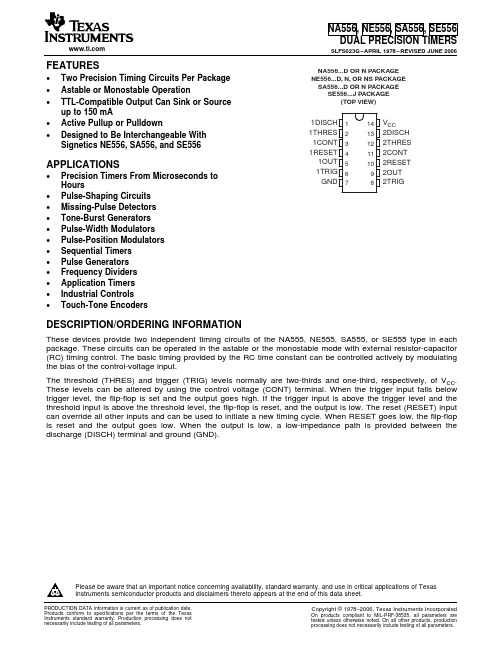
FEATURESAPPLICATIONS12345671413121110981DISCH1THRES1CONT1RESET1OUT1TRIGGNDV CC2DISCH2THRES2CONT2RESET2OUT2TRIG NA556...D OR N PACKAGENE556...D,N,OR NS PACKAGESA556...D OR N PACKAGESE556...J PACKAGE(TOP VIEW)DESCRIPTION/ORDERING INFORMATION NA556,NE556,SA556,SE556 DUAL PRECISION TIMERS SLFS023G–APRIL1978–REVISED JUNE2006•Two Precision Timing Circuits Per Package•Astable or Monostable Operation•TTL-Compatible Output Can Sink or Sourceup to150mA•Active Pullup or Pulldown•Designed to Be Interchangeable WithSignetics NE556,SA556,and SE556•Precision Timers From Microseconds toHours•Pulse-Shaping Circuits•Missing-Pulse Detectors•Tone-Burst Generators•Pulse-Width Modulators•Pulse-Position Modulators•Sequential Timers•Pulse Generators•Frequency Dividers•Application Timers•Industrial Controls•Touch-Tone EncodersThese devices provide two independent timing circuits of the NA555,NE555,SA555,or SE555type in each package.These circuits can be operated in the astable or the monostable mode with external resistor-capacitor (RC)timing control.The basic timing provided by the RC time constant can be controlled actively by modulating the bias of the control-voltage input.The threshold(THRES)and trigger(TRIG)levels normally are two-thirds and one-third,respectively,of V CC. These levels can be altered by using the control voltage(CONT)terminal.When the trigger input falls below trigger level,the flip-flop is set and the output goes high.If the trigger input is above the trigger level and the threshold input is above the threshold level,the flip-flop is reset,and the output is low.The reset(RESET)input can override all other inputs and can be used to initiate a new timing cycle.When RESET goes low,the flip-flop is reset and the output goes low.When the output is low,a low-impedance path is provided between the discharge(DISCH)terminal and ground(GND).Please be aware that an important notice concerning availability,standard warranty,and use in critical applications of TexasInstruments semiconductor products and disclaimers thereto appears at the end of this data sheet.GNDRESET can override TRIG,which can override THRES.NA556,NE556,SA556,SE556DUAL PRECISION TIMERSSLFS023G–APRIL 1978–REVISED JUNE 2006ORDERING INFORMATIONV T (MAX)T APACKAGE (1)ORDERABLE PART NUMBER TOP-SIDE MARKING V CC =15VPDIP –NTube of 25NE556N NE556N Tube of 50NE556D 0°C to 70°C11.2VSOIC –D NE556Reel of 2500NE556DR SOP –NSReel of 2000NE556NSR NE556–40°C to 85°C 11.2V PDIP –N Tube of 25SA556N SA556N PDIP –N Tube of 25NA556N NA556N –40°C to 105°C11.2VTube of 50NA556D SOIC –D NA556Reel of 2500NA556DR SE556J SE556J –55°C to 125°C 10.6VCDIP –JTube of 25SE556JBSE556JB(1)Package drawings,standard packing quantities,thermal data,symbolization,and PCB design guidelines are available at /sc/package.FUNCTION TABLE(each timer)TRIGGER THRESHOLD DISCHARGE RESET OUTPUT VOLTAGE (1)VOLTAGE (1)SWITCHLow Irrelevant Irrelevant Low On High <1/3V DD Irrelevant High Off High >1/3V DD >2/3V DD LowOnHigh >1/3V DD<2/3V DDAs previously established(1)Voltage levels shown are nominal.FUNCTIONAL BLOCK DIAGRAM,EACH TIMERAbsolute Maximum Ratings(1) Recommended Operating Conditions NA556,NE556,SA556,SE556 DUAL PRECISION TIMERS SLFS023G–APRIL1978–REVISED JUNE2006over operating free-air temperature range(unless otherwise noted)MIN MAX UNIT V CC Supply voltage(2)18VV I Input voltage CONT,RESET,THRES,and TRIG V CC VI O Output current±225mAD package86θJA Package thermal impedance(3)(4)N package80°C/WNS package76θJC Package thermal impedance(5)(6)J package15.05°C/W T J Operating virtual junction temperature150°C Lead temperature1,6mm(1/16in)from case for60s J package300°CLead temperature1,6mm(1/16in)from case for10s D,N,or NS package260°CT stg Storage temperature range–65150°C (1)Stresses beyond those listed under"absolute maximum ratings"may cause permanent damage to the device.These are stress ratingsonly,and functional operation of the device at these or any other conditions beyond those indicated under"recommended operating conditions"is not implied.Exposure to absolute-maximum-rated conditions for extended periods may affect device reliability.(2)All voltage values are with respect to network ground terminal.(3)Maximum power dissipation is a function of T J(max),θJA,and T A.The maximum allowable power dissipation at any allowable ambienttemperature is P D=(T J(max)–T A)/θJA.Operating at the absolute maximum T J of150°C can affect reliability.(4)The package thermal impedance is calculated in accordance with JESD51-7.(5)Maximum power dissipation is a function of T J(max),θJC,and T C.The maximum allowable power dissipation at any allowable casetemperature is P D=(T J(max)–T C)/θJC.Operating at the absolute maximum T J of150°C can affect reliability.(6)The package thermal impedance is calculated in accordance with MIL-STD-883.MIN MAX UNITNA556,NE556,SA556 4.516V CC Supply voltage VSE556 4.518V I Input voltage CONT,RESET,THRES,and TRIG V CC VI O Output current±200mANA556–40105NE556070T A Operating free-air temperature°CSA556–4085SE556–55125Electrical CharacteristicsNA556,NE556,SA556,SE556DUAL PRECISION TIMERSSLFS023G–APRIL 1978–REVISED JUNE 2006V CC =5V to 15V,T A =25°C (unless otherwise noted)NA556NE556SE556PARAMETERTEST CONDITIONSUNITSA556MINTYP MAX MIN TYP MAX V CC =15V 8.81011.29.41010.6Threshold voltage V T V levelV CC =5V2.43.34.2 2.73.34I TThreshold current (1)3025030250nA 4.555.64.855.2V CC =15VT A =–55°C to 125°C36V TRIGTrigger voltage levelV 1.11.672.21.451.671.9V CC =5VT A =–55°C to 125°C1.9I TRIG Trigger current TRIG at 0V0.520.50.9µA 0.30.710.30.71V RESET Reset voltage level V T A =–55°C to 125°C 1.1RESET at V CC 0.10.40.10.4I RESET Reset current mA RESET at 0V–0.4 1.5–0.4–1Discharge switch I DISCH2010020100nA off-state current 910119.61010.4V CC =15V T A =–55°C to 125°C9.610.4Control voltage V CONTV (open circuit)2.63.342.93.3 3.8V CC =5V T A =–55°C to 125°C2.93.80.10.250.10.15V CC =15V,I OL =10mA T A =–55°C to 125°C0.20.40.750.40.5V CC =15V,I OL =50mAT A =–55°C to 125°C122.522.2V CC =15V,I OL =100mA Low-levelT A =–55°C to 125°C2.7V OLV output voltageV CC =15V,I OL =200mA2.52.5V CC =5V,T A =–55°C to 125°C0.35I OL =3.5mA 0.10.250.10.15V CC =5V,I OL =5mAT A =–55°C to 125°C0.8V CC =5V,I OL =8mA 0.150.30.150.2512.7513.31313.3V CC =15V,I OH =–100mAT A =–55°C to 125°C12High-level V OHV CC =15V,I OH =–200mA 12.512.5Voutput voltage2.753.33 3.3V CC =5V,I OH =–100mA T A =–55°C to 125°C 2V CC =15V 20302024Output low,No loadV CC =5V 612610I CCSupply currentmAV CC =15V 18261820Output high,No loadV CC =5V41048(1)This parameter influences the maximum value of the timing resistors R and R B in the circuit of Figure 1.For example,when V CC =5V,the maximum value is R =R A +R B ≈3.4M Ω,and for V CC =15V,the maximum value is ≈10M Ω.Operating Characteristics NA556,NE556,SA556,SE556 DUAL PRECISION TIMERS SLFS023G–APRIL1978–REVISED JUNE2006VCC=5V and15VNA556NE556SE556TESTPARAMETER UNITSA556CONDITIONS(1)MIN TYP MAX MIN TYP MAXEach timer,130.5 1.5(4) monostable(3)Initial error of timingT A=25°Cinterval(2)Each timer,astable(5) 2.25% 1.5%Timer1–Timer2±1±0.5Each timer,5030100(4) Temperature monostable(3)coefficient of timing T A=MIN to MAX ppm/°C Each timer,astable(5)15090intervalTimer1–Timer2±10±10Each timer,0.10.50.050.2(4)Supply voltage monostable(3)sensitivity of timing T A=25°C%/V Each timer,astable(5)0.30.15intervalTimer1–Timer2±0.2±0.1C L=15pF,Output-pulse rise time100300100200(4)nsT A=25°CC L=15pF,Output-pulse fall time100300100200(4)nsT A=25°C(1)For conditions shown as MIN or MAX,use the appropriate value specified under recommended operating conditions.(2)Timing-interval error is defined as the difference between the measured value and the average value of a random sample from eachprocess run.(3)Values specified are for a device in a monostable circuit similar to Figure2,with the following component values:R A=2kΩto100kΩ,C=0.1µF.(4)On products compliant to MIL-PRF-38535,this parameter is not production tested.(5)Values specified are for a device in an astable circuit similar to Figure1,with the following component values:R A=1kΩto100kΩ,C=0.1µF.APPLICATION INFORMATIONOUTRR OUTNOTE A:Bypassing the control-voltage input to ground with acapacitor might improve operation.This should be evaluated for individual applications.NA556,NE556,SA556,SE556DUAL PRECISION TIMERSSLFS023G–APRIL 1978–REVISED JUNE 2006Figure 1.Circuit for Astable Operation Figure 2.Circuit for Monostable OperationPACKAGING INFORMATION(1) The marketing status values are defined as follows:ACTIVE: Product device recommended for new designs.LIFEBUY: TI has announced that the device will be discontinued, and a lifetime-buy period is in effect.NRND: Not recommended for new designs. Device is in production to support existing customers, but TI does not recommend using this part in a new design. PREVIEW: Device has been announced but is not in production. Samples may or may not be available.OBSOLETE: TI has discontinued the production of the device.Addendum-Page 1(2) RoHS: TI defines "RoHS" to mean semiconductor products that are compliant with the current EU RoHS requirements for all 10 RoHS substances, including the requirement that RoHS substance do not exceed 0.1% by weight in homogeneous materials. Where designed to be soldered at high temperatures, "RoHS" products are suitable for use in specified lead-free processes. TI may reference these types of products as "Pb-Free".RoHS Exempt: TI defines "RoHS Exempt" to mean products that contain lead but are compliant with EU RoHS pursuant to a specific EU RoHS exemption.Green: TI defines "Green" to mean the content of Chlorine (Cl) and Bromine (Br) based flame retardants meet JS709B low halogen requirements of <=1000ppm threshold. Antimony trioxide based flame retardants must also meet the <=1000ppm threshold requirement.(3) MSL, Peak Temp. - The Moisture Sensitivity Level rating according to the JEDEC industry standard classifications, and peak solder temperature.(4) There may be additional marking, which relates to the logo, the lot trace code information, or the environmental category on the device.(5) Multiple Device Markings will be inside parentheses. Only one Device Marking contained in parentheses and separated by a "~" will appear on a device. If a line is indented then it is a continuation of the previous line and the two combined represent the entire Device Marking for that device.(6) Lead finish/Ball material - Orderable Devices may have multiple material finish options. Finish options are separated by a vertical ruled line. Lead finish/Ball material values may wrap to two lines if the finish value exceeds the maximum column width.Important Information and Disclaimer:The information provided on this page represents TI's knowledge and belief as of the date that it is provided. TI bases its knowledge and belief on information provided by third parties, and makes no representation or warranty as to the accuracy of such information. Efforts are underway to better integrate information from third parties. TI has taken and continues to take reasonable steps to provide representative and accurate information but may not have conducted destructive testing or chemical analysis on incoming materials and chemicals. TI and TI suppliers consider certain information to be proprietary, and thus CAS numbers and other limited information may not be available for release.In no event shall TI's liability arising out of such information exceed the total purchase price of the TI part(s) at issue in this document sold by TI to Customer on an annual basis.Addendum-Page 2TAPE AND REEL INFORMATIONA0B0K0W Dimension designed to accommodate the component length Dimension designed to accommodate the component thickness Overall width of the carrier tapePitch between successive cavity centersDimension designed to accommodate the component width TAPE DIMENSIONSSprocket HolesP1*All dimensions are nominalDevicePackage Type Package Drawing Pins SPQReel Diameter (mm)Reel Width W1 (mm)A0(mm)B0(mm)K0(mm)P1(mm)W (mm)Pin1Quadrant NA556DR SOIC D 142500330.016.4 6.59.0 2.18.016.0Q1NE556DBR SSOP DB 142000330.016.48.35 6.6 2.412.016.0Q1NE556DR SOIC D 142500330.016.4 6.59.0 2.18.016.0Q1NE556NSRSONS142000330.016.48.210.52.512.016.0Q1*All dimensions are nominalDevice Package Type Package Drawing Pins SPQ Length (mm)Width (mm)Height (mm) NA556DR SOIC D142500356.0356.035.0 NE556DBR SSOP DB142000356.0356.035.0 NE556DR SOIC D142500356.0356.035.0 NE556NSR SO NS142000356.0356.035.0PACKAGE MATERIALS INFORMATION 1-Jul-2023 TUBET - Tube*All dimensions are nominalDevice Package Name Package Type Pins SPQ L (mm)W (mm)T (µm) B (mm)NA556D D SOIC1450506.683940 4.32NA556N N PDIP142550613.9711230 4.32NA556N N PDIP142550613.9711230 4.32NE556D D SOIC1450506.683940 4.32NE556N N PDIP142550613.9711230 4.32NE556N N PDIP142550613.9711230 4.32NE556NE4N PDIP142550613.9711230 4.32NE556NE4N PDIP142550613.9711230 4.32SA556N N PDIP142550613.9711230 4.32SA556NE4N PDIP142550613.9711230 4.32PACKAGE OUTLINECDIP - 5.08 mm max heightJ0014A CERAMIC DUAL IN LINE PACKAGENOTES:1. All controlling linear dimensions are in inches. Dimensions in brackets are in millimeters. Any dimension in brackets or parenthesis are for reference only. Dimensioning and tolerancing per ASME Y14.5M.2. This drawing is subject to change without notice.3. This package is hermitically sealed with a ceramic lid using glass frit.4. Index point is provided on cap for terminal identification only and on press ceramic glass frit seal only.5. Falls within MIL-STD-1835 and GDIP1-T14.EXAMPLE BOARD LAYOUTCDIP - 5.08 mm max heightJ0014A CERAMIC DUAL IN LINE PACKAGEMECHANICAL DATAMSSO002E – JANUARY 1995 – REVISED DECEMBER 2001DB (R-PDSO-G**)PLASTIC SMALL-OUTLINE4040065/E 12/0128 PINS SHOWNGage Plane8,207,400,550,950,253812,9012,302810,50248,50Seating Plane9,907,903010,509,900,385,605,00150,2214A 28120166,506,50140,05 MIN 5,905,90DIMA MAX A MIN PINS **2,00 MAX 6,907,500,65M 0,150°–ā8°0,100,090,25NOTES: A.All linear dimensions are in millimeters.B.This drawing is subject to change without notice.C.Body dimensions do not include mold flash or protrusion not to exceed 0,15.D.Falls within JEDEC MO-150IMPORTANT NOTICE AND DISCLAIMERTI PROVIDES TECHNICAL AND RELIABILITY DATA (INCLUDING DATA SHEETS), DESIGN RESOURCES (INCLUDING REFERENCE DESIGNS), APPLICATION OR OTHER DESIGN ADVICE, WEB TOOLS, SAFETY INFORMATION, AND OTHER RESOURCES “AS IS” AND WITH ALL FAULTS, AND DISCLAIMS ALL WARRANTIES, EXPRESS AND IMPLIED, INCLUDING WITHOUT LIMITATION ANY IMPLIED WARRANTIES OF MERCHANTABILITY, FITNESS FOR A PARTICULAR PURPOSE OR NON-INFRINGEMENT OF THIRD PARTY INTELLECTUAL PROPERTY RIGHTS.These resources are intended for skilled developers designing with TI products. You are solely responsible for (1) selecting the appropriate TI products for your application, (2) designing, validating and testing your application, and (3) ensuring your application meets applicable standards, and any other safety, security, regulatory or other requirements.These resources are subject to change without notice. TI grants you permission to use these resources only for development of an application that uses the TI products described in the resource. Other reproduction and display of these resources is prohibited. No license is granted to any other TI intellectual property right or to any third party intellectual property right. TI disclaims responsibility for, and you will fully indemnify TI and its representatives against, any claims, damages, costs, losses, and liabilities arising out of your use of these resources.TI’s products are provided subject to TI’s Terms of Sale or other applicable terms available either on or provided in conjunction with such TI products. TI’s provision of these resources does not expand or otherwise alter TI’s applicable warranties or warranty disclaimers for TI products.TI objects to and rejects any additional or different terms you may have proposed.Mailing Address: Texas Instruments, Post Office Box 655303, Dallas, Texas 75265Copyright © 2023, Texas Instruments Incorporated。
BF556A资料

Top view
MAM036
Marking codes: BF556A: M84. BF556B: M85. BF556C: M86.
Fig.1 Simplified outline and symbol.
The device is supplied in an antistatic package. The gate-source input must be protected against static discharge during transport or handling.
元器件交易网
Philips Semiconductors
Product specification
N-channel silicon junction field-effect transistors
FEATURES • Low leakage level (typ. 500 fA) • High gain • Low cut-off voltage.
元器件交易网
DISCRETE SEMICONDUCTORS
DATA SHEET
BF556A; BF556B; BF556C N-channel silicon junction field-effect transistors
Product specification Supersedes data of April 1995 File under Discrete Semiconductors, SC07 1996 Jul 29
BF556A; BF556B; BF556C
handbook, halfpage 2
1
g
d s
APPLICATIONS • Impedance converters in e.g. electret microphones and infra-red detectors • VHF amplifiers in oscillators and mixers. DESCRIPTION N-channel symmetrical silicon junction field-effect transistors in a SOT23 package. PINNING - SOT23 PIN 1 2 3 SYMBOL s d g drain gate‘ DESCRIPTION source CAUTION
sa556标准

sa556标准
sa556是一款集成的双555定时器,由一家名为STM(意法半导体)的公司生产。
该芯片具有两个独立的555定时器,可用于各种定时和脉冲生成应用。
该芯片的主要特性包括:
- 双555电压比较器/定时器
- 宽电源电压范围(3V-18V)
- 可独立配置为稳态(单稳态)、多谐波振荡器和定时器
- 内部RS触发器用于稳态触发,可外部配置
- 输入输出电平兼容CMOS、TTL和HTL逻辑电平
- 高电流输出驱动能力(200mA)
- 可以通过外部电位器进行频率和占空比调节
使用sa556标准可以方便地实现各种定时和脉冲生成功能,常见应用包括电子钟、脉冲发生器、触发器等。
它的功能强大且易于使用,适合电子爱好者和工程师使用。