PROXPAC_ 接近式传感器组件
iProx 引导型接近传感器安装接近的数据TD05301002E说明书

iProx inductive proximity sensors—mounting close togetherDescriptionThe iProxீ is a powerful family of inductive proximity sensors featuring high sensing performance right out of the box. What makes the iProx unique from other inductive sensors is the ability to extensively customize the operating characteristics to suit a particular application.Mounting sensors close togetherWhen mounting iProx sensors close together, it is necessary to take into consideration problems that can be causedby two or more sensors communicating with each other (also known as “cross-talk”). This problem can arise when two or more sensors are mounted side by side (as shown in Figure 1) or facing each other (as shown in Figure 2).Figure 1. Proximity Sensors Mounted Side by SideFigure 2. Proximity Sensors Mounted Facing Each Other Standard inductive proximity sensors have a similar frequency and will interfere with each other when operated close together. Until iProx, your best solution may have been to buy special sensors designed to operate on different frequencies. The disadvantage of this solution is that your choice of sensing range and body style is usually very limited.The DC versions of iProx have three different noise immunity settings, while the AC versions have two settings. See Figure 3, Figure 4, Figure 5, and Figure 6 for optimum noise immunity settings based upon center-to-center spacing between mounted sensors. Note that in some cases, more than one noise immunity setting is available. In this case,the operator can choose the combinations of noise immunity settings most desirable for the application. The iProx breaks many of the traditional rules of inductive proximity sensors. For instance, it is possible to mount the sensors so that the sensing fields overlap, so long as the proper noise immunity settings are chosen.Figure 3. DC iProx Side-by-Side Configuration (S1)T able 1. DC iProx Side-by-Side Configuration (S1)Diameter (D)Sideby SideHigh NoiseImmunityFactoryDefault12 mm Shielded0–19 mmat 50 Hz0 mm–Infinityat 10 Hz30 mm–Infinityat 580 HzUnshielded0–40 mmat 50 Hz0 mm–Infinityat 10 Hz100 mm–Infinityat 300 Hz18 mm Shielded0–35 mmat 50 Hz0 mm–Infinityat 10 Hz80 mm–Infinityat 390 HzUnshielded0–75 mmat 50 Hz0 mm–Infinityat 10 Hz130 mm–Infinityat 150 Hz30 mm Shielded0–65 mmat 50 Hz0 mm–Infinityat 10 Hz110 mm–Infinityat 240 HzUnshielded0–75 mmat 50 Hz0 mm–Infinityat 10 Hz130 mm–Infinityat 90 Hz2Technical Data TD05301002EEffective June 2013iProx inductive proximity sensors—mounting close togetherEATON Figure 4. DC iProx Facing Configuration (S 2)T able 2. DC iProx Facing Configuration (S 2)Diameter (D)Side by SideHigh Noise ImmunityFactory Default12 mm Shielded 0–25 mm at 50 Hz 0 mm–Infinity at 10 Hz50 mm–Infinity at 580 HzUnshielded0–55 mm at 50 Hz 0 mm–Infinity at 10 Hz120 mm–Infinity at 300 Hz18 mm Shielded 0–45 mm at 50 Hz 0 mm–Infinity at 10 Hz100 mm–Infinity at 390 HzUnshielded0–90 mm at 50 Hz 0 mm–Infinity at 10 Hz160 mm–Infinity at 150 Hz30 mm Shielded 0–80 mm at 50 Hz 0 mm–Infinity at 10 Hz130 mm–Infinity at 240 HzUnshielded0–90 mm at 50 Hz 0 mm–Infinity at 10 Hz 160 mm–Infinity at 90 HzFigure 5. AC iProx Side-by-Side Configuration (S 1)T able 3. AC iProx Side-by-Side Configuration (S 1) ቢDiameter (D)Factory DefaultHigh Noise Immunity12 mm Shielded 0–19 mm/30 mm–Infinity at 30 Hz 0 mm–Infinity at 10 HzUnshielded0–40 mm/50 mm–Infinity at 30 Hz 0 mm–Infinity at 10 Hz18 mm Shielded 0–35 mm/80 mm–Infinity at 30 Hz 0 mm–Infinity at 10 HzUnshielded0–75 mm/130 mm–Infinity at 30 Hz 0 mm–Infinity at 10 Hz30 mm Shielded 0–65 mm/110 mm–Infinity at 30 Hz 0 mm–Infinity at 10 HzUnshielded0–75 mm/130 mm–Infinity at 30 Hz0 mm–Infinity at 10 HzቢThese specifications may not meet final product specifications.Figure 6. AC iProx Facing Configuration (S 2)T able 4. AC iProx Facing Configuration (S 2) ቢDiameter (D)Factory DefaultHigh Noise Immunity12 mm Shielded 0–25 mm/50 mm–Infinity at 30 Hz 0 mm–Infinity at 10 HzUnshielded0–55 mm/120 mm–Infinity at 30 Hz 0 mm–Infinity at 10 Hz18 mm Shielded 0–45 mm/100 mm–Infinity at 30 Hz 0 mm–Infinity at 10 HzUnshielded0–90 mm/160 mm–Infinity at 30 Hz 0 mm–Infinity at 10 Hz30 mm Shielded 0–80 mm/130 mm–Infinity at 30 Hz 0 mm–Infinity at 10 HzUnshielded0–90 mm/160 mm–Infinity at 30 Hz0 mm–Infinity at 10 Hzቢ These specifications may not meet final product specifications.ote:N There is a correlation between noise immunity and operatingfrequency. When setting the sensor for side-by-side sensing or high noise immunity, the operating frequency of the sensor will be reduced. Refer to the iProx Programming Software User Guide (P50228) for details.3Technical Data TD05301002EEffective June 2013iProx inductive proximity sensors—mounting close togetherEATON Setting iProx for side-by-side or facing sensingTo set up iProx sensors for side-by-side or face-to-face operation, just follow the simple procedure below. This process requires that the iProx programming software be installed on your computer. Consult the iProx Programming Software User Guide (P50228) for detailed installation and operating instructions.1. Connect the programming device to your computer. Connectthe remote programmer (E59RP1) to your computer’s serial or USB port. 2. Launch that the iProx programming software from the Start menu.3. Affix the magnetic puck to the face of the iProx sensor. To ensureproper mounting, it may be necessary to remove the mounting nuts from the sensor.4. Ensure that the sensor(s) you intend to program are powered on.5. The iProx programming software should automatically detect thesensor(s). See the “Connection Status” information displayed at the bottom of the “Getting Started” window to confirm that the software has detected the sensor(s). If the software does not detect the connected sensor, you may need to select a wider COM port range in the software settings. For more troubleshooting information, consult the iProx Programming Software User Guide (P50228) by clicking on the “Help” window and selecting “Contents/FAQs.”6. From the “Getting Started” window, click “Configure iProx” to modify the parameters of your iProx sensor.7. Under “Step 1: Select Sensor to Modify,” click the drop-downmenu and select the sensor you want to modify. It may take a few seconds to communicate with the sensor. Once this is complete, the rest of the screen should become enabled, allowing you to modify the parameters of the selected sensor.8. Under the “Response Time/Noise Immunity” section at the topright of the screen, drag the slider until you see the side-by-side value enabled.9. Click the “Program” button at the bottom of the screen. Repeatthis process for each sensor.Side-by-side vs. array sensingAlthough this procedure allows sensors to be operated close to other sensors in a side-by-side configuration (see Figure 7), Eaton does not recommend that iProx sensors be used in an array (Figure 8). It is possible that cross-ommunication can occur between sensors in an array. If the requirements of your application call for this arrangement, please contact Eaton’s Sensor ApplicationEngineering Department at 1-800-426-9184. They will work with youto find a solution.Figure 7. Sensors Oriented Side by SideFigure 8. Sensors Oriented in an ArrayTechnical Data TD05301002E Effective June 2013iProx inductive proximity sensors—mounting close togetherEaton is a registered trademark.All other trademarks are propertyof their respective owners.Eaton1000 Eaton BoulevardCleveland, OH 44122United States© 2013 EatonAll Rights ReservedPrinted in USAPublication No. TD05301002E / Z13430 June 2013。
ProMix

修理零配件ProMix®PD2K电子配比器334266LZH 针对双组件涂料的电子正排量定量器。
配有高级显示模块的手动系统。
仅供专业人员使用。
重要安全说明请阅读本手册中的所有警告和说明。
请妥善保存这些说明。
有关各型号的零配件编号和认证信息,请参见第3页。
PROVEN QUALITY.LEADING TECHNOLOGY.Contents型号 (3)相关手册 (6)警告 (7)异氰酸酯(ISO)的重要信息 (10)重要的酸性催化剂信息 (12)酸性催化剂情况 (12)酸性催化剂的湿气敏感性 (12)故障排除 (13)系统故障排除 (13)故障代码排除 (14)喷涂间控制台故障排除 (25)电源栅栏板故障排除 (26)隔离板故障排除 (27)增强型流体控制模块故障排除 (28)泵模块故障排除 (29)高级显示模块故障排除 (30)电气示意图 (31)标准型号(MC1000、MC2000、MC3000、MC4000) (31)双面板型号(MC1002、MC2002、MC3002、MC4002) (38)可选的电缆和模块 (44)通信选项(用于PLC和AWI)...................45修理. (46)维修之前的工作 (46)泄压步骤 (47)修理高级显示模块(ADM) (48)维修控制箱 (49)维修流体通路段 (58)零部件 (63)定量器零件(标准型号) (63)定量器零件(双面板型号) (66)控制盒零件(标准型号) (69)控制盒零件(双面板型号) (72)电磁阀歧管部件 (75)修理配件包和附件 (76)软管束 (76)腰带歧管涂料混合套件 (77)本质安全的远程变色套件 (77)换色和更换催化剂套件 (78)式喷枪 (78)泵扩展套件 (79)通信套件 (79)升级套件 (79)注释 (80)技术数据 (81)型号型号参见图1-7获取组件识别标牌,包括核准信息和认证。
WILLIAMSON 非接触式红外线温度传感器 PRO 说明书

坚固耐腐蚀的、符合美国电气制造协会 NEMA4X (IP65)标准的外壳,适用于恶劣的操作环境。 业界领先的信号稀释因数组令双波长和多波长传感器能 够容忍以下不利情况:被侧目标太小或晃动、镜头没对 准、有阻障、只有局部视野或脏污镜头。
更易于使用
直观的、以文本为基础的用户界面简化了安装及操作。 无须手册和特殊培训来翻译容易混淆的代码或来调节传 感器。
PRO 系列菜单系统
显示模式:可查看 5 个被测参数,十三个系统设定值和四个
状态信息
被测参数
- 过滤后的目标温度
- 未过滤的目标温度
- 环境温度
- 信号稀释(只用于 和 )
- 信号强度/发射率(只用于 )
状态信息
- 超过测量温度范围 - 高环境温度报警 - 请查看传感器连接电缆 - 瞄准系统的状态
设定模式:显示并编辑所有系统参数
可预先编程的输出方式和报警信号由 5 个测量参数匹配 组成,实现了对不同类型的过程监测和控制能力。
通过利用镜头传感器或光纤可视传感器提供灵活、精确 的多种可选的瞄准方式。可额外选用的瞄准光源和激光 瞄准系统能令用户很容易地核实瞄准是否得当。
更为精确
先进的信号采样和处理系统,能在更大的温度范围和不利 条件下提供更为精确的温度测量。 先进的发射率补偿技术,诸如可编程的 ESP 算法,实现 可在复杂测量应用中做到“即描即读”的能力。
发射率是一个技术术语,用以确定在给定温度下相 对于它的理论最大值。通常大多数的应用场合使用单波 长传感器就可以了,因为大多数物质显示高而恒定的发 射率。但是在金属测量应用中,其表面发射率低而且是 变化的,要得到精确而可靠的测量,最好是使用双波长 或多波长传感器。
PRO 系列传感器提供了一套完整的传感器选择以满 足来自具有不同发射率的应用场合的要求。下表可为帮 助用户就每种应用选择最合适的传感器提供一些指导。
接近传感器工作原理及分类和选型

接近传感器工作原理及分类和选型接近传感器被广泛用于各种自动化生产线,机电一体化设备及石油、化工、军工、科研等多种行业,那什么是接近传感器呢?接近传感器接近传感器,是指代替限位开关等接触式检测方式,以无需接触检测对象进行检测为目的的传感器的总称。
其能将检测对象的移动信息和存在信息转换为电气信号。
在转换为电气信号的检测方式中,包括利用电磁感应引起的检测对象的金属体中产生的涡电流的方式、捕测体的接近引起的电气信号的容量变化的方式、利石和引导开关的方式。
由感应型、静电容量型、超声波型、光电型、磁力型等构成。
接近传感器是利用振动器发生的一个交变磁场,当金属目标接近这磁场并达到感应距离时,在金属目标内发生涡流,因此导致振动衰减,以至接近传感器的振动器停振。
接近传感器的振动器振动及停振的变化被后级放大电路处理并转换成开关信号,触发驱动控制器件,因此达到接近传感器的非接触式之检测的目的。
这就是接近传感器的运作原理。
技术优势①由于其能以非接触方式进行检测,所以不会磨损和损伤检测对象物。
②由于采用无接点输出方式,因此寿命延长(磁力式除外)采用半导体输出,对接点的寿命无影响。
③与光检测方式不同,适合在水和油等环境下使用检测时几乎不受检测对象的污渍、油和水等的影响。
此外,还包括特氟龙外壳型及耐药品良好的产品。
④与接触式开关相比,可实现高速响应。
⑤能对应广泛的温度范围。
⑥不受检测物体颜色的影响:对检测对象的物理性质变化进行检测,所以几乎不受表面颜色等的影响。
⑦与接触式不同,会受周围温度、周围物体、同类传感器的影响,包括感应型、静电容量型在内,传感器之间相互影响。
因此,对于传感器的设置,需要考虑相互干扰。
此外,在感应型中,需要考虑周围金属的影响,而在静电容量型中则需考虑周围物体的影响。
当金属检测体接近传感器的感应区域,开关能无接触,无压力、无火花、迅速发出电气指令,准确反应出运动机构的位置和行程,即使用于一般的行程控制,其定位精度、操作频。
红外接近传感器的工作原理

红外接近传感器的工作原理红外接近传感器(InfraredProximitySensor,简称IPS)是一种能够利用红外发射器与接收器检测物体距离的装置,最早是用来检测火车轨道上的障碍物,随着电子技术的发展,现在IPS可以用于电子游戏,智能家居等诸多领域。
IPS对技术非常重要,因为它能够感受到两种接近物体的距离,从而控制电子设备的运作。
IPS有着简单的结构,可以简单的分为三个部分:红外发射器,红外接收器以及处理部分。
红外发射器利用电能产生脉冲红外光,而红外接收器则负责接收来自红外发射器的脉冲红外光。
接收器还可以注意到环境中的热量,从而避免障碍物的准确探测。
IPS的实际运行原理是:当红外发射器发射出红外脉冲,当物体与传感器之间有距离时,红外光会被反射回红外接收器,接收器会将接收到的红外信号转换为电信号,发送个处理部分。
而当物体靠近传感器时,红外光将会被物体吸收,接收器就不会接收到脉冲红外光,从而也不会传输电信号到处理部分,处理部分就会根据是否接收到电信号来判断物体是否被探测。
IPS的特性十分多样,根据应用的不同,它可以是一个简单的近接传感器,也可以是一个多功能的传感器,如倾斜传感器、振动传感器等,在机器人技术中经常使用。
IPS的应用十分广泛,在安全技术中应用广泛,比如可以应用于车辆停车距离控制、防盗报警、人脸检测等技术;也可以应用于电子游戏中,比如虚拟现实中弹跳关卡、火焰墙等技术。
此外,IPS在智能家居中也得到应用,它可以检测居室内移动物体的距离,从而实现自动调节通风、照明、安防等功能。
同时,IPS还可以应用于医疗机器人,可以通过IPS检测到患者的体温等信息,可以帮助医生以及护士们正确的诊断患者,使治疗更有效。
综上所述,IPS结构简单、特性多样、应用非常广泛,是非常实用的一种传感器,在技术领域的应用可谓多端,帮助我们更好的探测物体的距离,并实现有效的控制,从而提高技术的效率。
洛施达电容式接近开关

洛施达电容式接近开关是一种传感器,其特点是利用电容变化来检测物体的接近。
这种类型的开关广泛应用于工业自动化和控制系统中,用于检测物体的位置、距离或存在与否。
洛施达电容式接近开关的主要优点包括非接触式检测、高灵敏度、快速响应和良好的抗干扰能力。
它们通常用于检测金属或非金属物体,适用于各种环境和应用场景。
洛施达电容式接近开关的工作原理是:当目标物体接近开关的感应面时,会引起电容量的变化,这个变化会被传感器检测到并转换成电信号输出。
通过这种方式,开关可以实现对物体位置的精确检测和控制。
洛施达电容式接近开关的应用范围非常广泛,包括机械设备、自动化设备、生产线、仓储系统等领域。
它们可以用于检测物料的位置、控制机械臂的运动、实现自动化生产线的计数和分拣等功能。
需要注意的是,不同类型的洛施达电容式接近开关具有不同的特点和适用范围,因此在选择和使用时需要根据具体的应用场景和需求进行选择。
此外,正确的安装和调试也是确保开关性能稳定和可靠运行的关键。
本特利产品说明
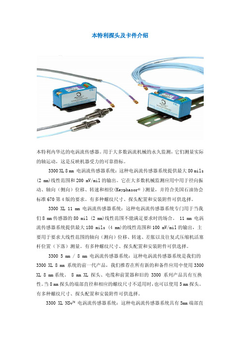
本特利探头及卡件介绍本特利内华达的电涡流传感器。
用于大多数涡流机械的永久监测,它们测量实际的轴运动,这是反映机器受力的可靠指标。
3300 XL 8 mm 电涡流传感器系统:这种电涡流传感器系统提供最大80 mils (2 mm)线性范围和200 mV/mil的输出。
它在大多数机械监测应用中用于径向振动、轴向(侧向)位移、转速和相位(Keyphasor® )测量,并符合美国石油协会标准670第4版的要求。
有多种螺纹尺寸、探头配置和安装附件可供选择。
3300 XL 11 mm 电涡流传感器系统:这种电涡流传感器系统专门用于当我们8 mm传感器的80 mil (2 mm)线性范围不能满足要求时的场合。
11 mm 电涡流传感器系统提供最大180 mils (4 mm)的线性范围和100 mV/mil的输出,主要用于要求大线性范围的轴向(测向)位移、转速、差胀以及往复式压缩机活塞杆位置(下落)测量。
有多种螺纹尺寸、探头配置和安装附件可供选择。
3300 5 mm / 8 mm 电涡流传感器系统:这种电涡流传感器系统是我们的3300 XL 8 mm 系统的前一代产品,我们推荐在所有新的和备件应用中使用3300 XL 8 mm系统。
8 mm XL 探头、电缆和前置器和旧的 3300 系列产品具有互换性。
当8 mm探头的端部直径和相应的螺纹尺寸不适用时,也可以使用5 mm探头。
有多种螺纹尺寸、探头配置和安装附件可供选择。
3300 XL NSv™ 电涡流传感器系统:这种电涡流传感器系统具有5mm端部直径和60 mils (1.5 mm)的更短线性范围,适用于被测靶面区域小、侧视或沉孔间隙减小以及其它限制使用我们标准的 5 mm / 8 mm 电涡流传感器的情况。
3300 16 mm 高温电涡流传感器系统:这种电涡流传感器系统用于最高350℃ (662°F)的高温环境,如温度超过我们标准电涡流探头和电缆能够承受的极限的某些燃气和蒸汽轮机应用。
p+f倍加福传感器的特点_2

p+f倍加福传感器的特点德国倍加福P+F(Pepperl+Fuchs)接近传感器的工作原理1、概述Pepperl+Fuchs P+F接近传感器可以检测到靠近传感器的金属物体,而无需实际接触目标。
工作原理上,接近传感器大致可分为以下三类:电磁感应使用高频振荡型,电磁磁铁使用型和电容变电容式。
特性:①非接触式检测,以避免损坏传感器本身和目标。
②无触点输出,使用寿命长。
③在有水或油溅出的恶劣环境中稳定检测。
④反应快。
⑤小传感器头,安装灵活。
2、类型(1)根据配置(2)根据测试方法①通用类型:主要检测黑色金属(铁)。
②所有金属类型:在相同的检测距离内检测任何金属。
③有色金属类型:主要检测铝等有色金属。
3、高频振荡型Pepperl+Fuchs P+F接近传感器的工作原理Pepperl+Fuchs P+F电感式接近传感器由高频振荡,检测,放大,触发和输出电路组成。
振荡器传感器检测表面产生交变电磁场。
当金属物体接近传感器检测表面时,金属中的涡流会吸收振荡器能量,从而使振荡减弱并停止。
振荡器振荡和停止振动的两种状态都转换为电信号。
整形放大并转换为二进制开关信号,在功率放大后输出。
以下是详细的介绍:(1)Pepperl+Fuchs P+F通用接近传感器有效振幅变化的程度根据靶的金属的种类而变化,检测距离也根据靶的金属的种类而变化。
(2)所有金属传感器的工作原理所有金属型传感器基本上都是高频振荡型的。
像普通类型一样,它也有一个振荡电路,由于目标电流中感应电流的流失而导致能量的损失,因此会影响振荡频率。
当目标接近传感器时,目标金属类型将增加并且振荡频率将增加。
传感器检测到此变化并输出检测信号。
(3)有色金属传感器的工作原理有色金属传感器基本上是高频振荡类型的。
它具有一个振荡电路,该振荡电路由于感应电流在物体中的流动而导致的能量损耗而影响振荡频率。
当铝或铜之类的有色金属目标靠近传感器时,振荡频率为增高。
当铁等黑色金属物体靠近传感器时,振荡频率会降低。
- 1、下载文档前请自行甄别文档内容的完整性,平台不提供额外的编辑、内容补充、找答案等附加服务。
- 2、"仅部分预览"的文档,不可在线预览部分如存在完整性等问题,可反馈申请退款(可完整预览的文档不适用该条件!)。
- 3、如文档侵犯您的权益,请联系客服反馈,我们会尽快为您处理(人工客服工作时间:9:00-18:30)。
Specifications and Ordering InformationPart Number 178554-01Rev. NC (10/07)PROXPAC XL Proximity Transducer AssemblyDescriptionThe design of the PROXPAC XL® Proximity Transducer Assembly is similar to our 31000/32000 Proximity Probe Housing Assemblies. The assembly offers the same advantages and features as the 31000 and 32000 housings for accessing and externally adjusting proximity probes. However, the housing cover of the PROXPAC XL Assembly also contains its own 3300 XL Proximitor® sensor. This design makes the PROXPAC XL Assembly a completely self-contained proximityprobe system, and eliminates the need for an extension cable between the probe and its associated Proximitor sensor. It also eliminates the need for a separate Proximitor housing, as the field wiring connects directly between the monitors and PROXPAC XL Assemblies.The PROXPAC XL housing is made of Polyphenylene Sulfide (PPS), which is an advanced, molded thermoplastic. This material replaces the steel and aluminum in previous housings offered in the Bently Nevada product line, It alsoincorporates glass and conductive fibers in the PPS to strengthen the housing and more effectively dissipate electrostatic charges. The PROXPAC XL housing is rated for Type 4X and for IP66 environments and provides extra protection in severe environments.SpecificationsElectricalProximitorSensor Input3300 XL 8 mm Proximity Probewith a 1-metre cable lengthinstalled in the probe sleeve. PowerRequires -17.5 Vdc to -26 Vdcwithout barriers at 12 mAmaximum consumption, -23 Vdcto -26 Vdc with barriers.Operation at a more positivevoltage than -23.5 Vdc can resultin reduced linear range.SupplySensitivityLess than 2 mV change in outputvoltage per volt change in inputvoltage.Outputresistance:50 ΩNominal ProbeDC Resistance(R PROBE):See Table 1.Table 1: Resistance from the Center Conductor tothe Outer ConductorProbe Length (m) R PROBE (O)1.0 7.59 ± 0.50Field wiring:0.2 to 1.5 mm2(16 to 24 AWG) .Recommend using 3-conductorshielded triax cable and tinnedfield wiring. Maximum length of305 metres (1,000 feet) betweenthe 3300 XL Proximitor Sensorand the monitor. See thefrequency response graph (Figure1, page 7) for signal rolloff at highfrequencies when using longerfield wiring lengths.Linear Range:2 mm (80 mils). Linear rangebegins at approximately 0.25 mm(10 mils) from target and is from0.25 mm to 2.3 mm (10 mils to 90mils) (approximately –1 Vdc to –17Vdc).RecommendedGap Setting:1.27 mm (50 mils)IncrementalScale Factor(ISF)7.87 V/mm (200 mV/mil) ±5%including interchangeability errorwhen measured in increments of0.25 mm (10 mils) over the 80 millinear range from 0 °C to +45 °C(+32 °F to +113 °F).Deviation from best fit straight line (DSL) Standard 1metre systemLess than ±0.025mm (±1 mil) withcomponents at 0 °C to +45 °C(+32 °F to +113 °F).FrequencyResponse0 to 10 kHz: +0, -3 dB, with up to305 metres (1000 feet) of fieldwiring.MinimumTarget Size15.2 mm (0.6 in) diameter (flattarget)Shaft DiameterMinimum50.8 mm (2.0 in)Specifications and Ordering InformationRecommendedminimum76.2 mm (3.0 in)When gapped at the center of thelinear range, the interactionbetween two separate transducersystems (cross-talk) will be lessthan 50 mV on shaft diameters ofat least 50 mm (2.0 in) or greater.Care should be taken to maintainminimum separation oftransducer tips, generally at least40 mm (1.6 in) for axial positionmeasurements or 38 mm (1.5 in)for radial vibration measurementsto limit cross-talk to 50 mV or less.Radial vibration or positionmeasurements on shaftdiameters smaller than 76.2 mm(3.0 in) will generally result in achange in scale factor. ConsultPerformance Specification159484 for additional information. Effects of 60 HzMagnetic FilesUp To 300GaussSee Table 2.Table 2: Output Voltage in Mil pp/GaussGap (mils) 1-metre ProximitorSensorProbe10 0.0124 0.000450 0.0110 0.001490 0.0126 0.0045Electrical Classification:Complies with the European CEmark.Hazardous Area ApprovalsNorth America:Ex ia IIC T4/T5; Class I Zone 0 orClass 1 Division 1; Groups A, B, C,and D, when installed withintrinsically safe zener barriersper drawing 141092 or wheninstalled with galvanic isolators.Certificate number 1109248 (LR26744-222)Ex nA IIC T4/T5 Class I Zone 2 orClass I, Division 2, Groups A, B, C,and D when installed withoutbarriers per drawing 140979.T5 @ Ta = -35 °C to +85 °C.T4 @ Ta= -51 °C to +100 °C.Certificate number 1109248 (LR26744-222)Europe:II 1 G EEx ia IIC T4/T5. ECcertificate numberBAS99ATEX1101, when installedper drawing 141092.II 3 G EEx nAII T4/T5. ECcertificate number BASEEFA 07ATEX 0189 X,when installed perdrawing 140979T5 @ Ta= -35 °C to +85 °CT4 @ Ta= -51 °C to +100 °C.IEC Ex3300 XL Proximitor Sensor, iaIECEx BAS04.0055XEx ia IIC T4 / T5 (-51ºC = Ta =+100ºC / -35ºC = Ta = +85ºC) Terminal BlockConnectionsUi= -28 V Ci = 0 nFIi= 140 mA Li =10 µHPi= 0.84 WCoaxialConnectionUi = -28 V Ci= 5.7 nFIi = 140 mA Li = 0.85 mHPi = 0.84 WLoadParametersThe capacitance and either theinductance or the inductance toresistance (L/R) ratio of the loadconnected to the probe coaxialSpecifications and Ordering Informationterminal, must not exceed thevalues in Table 3.Table 3: Maximum Load ParametersGroup Capacitance(µF)Inductance(mH)L/R Ratio(uH/O)IIC 0.077 0.99 35IIB 0.644 7.41 142IIA 2.144 15.6 295 3300 XLProximitorSensor, nAIECEx BAS04.0057XAEx nA II T4 / T5 (-51 ºC = Ta =+100 ºC / -35 ºC = Ta = +85 ºC)Ui = -28 V3300 XL 8mmEddy CurrentProbe, iaIECEx BAS04.0056AEx ia IIC TemperatureClassification per Table 4 below. Table 4: Aex ia IIC Temperature Classifications TemperatureClassificationAmbient Temperature T1 -51 ºC to +232 ºCT2 -51 ºC to +177 ºCT3 -51 ºC to +120 ºCT4 -51 ºC to +80 ºCT5 -51 ºC to +40 ºCUi = -28 V Ci = 1.5 nFIi = 140 mA Li = 200 µHPi =0.84 W3300 XL 8mmEddy CurrentProbe, nAIECEx BAS04.0058XEx nA II TemperatureClassification per the table above.Must be supplied from a voltagelimited source.EEx nA for Zone 2, Group IIC, ECcertificate numberBAS99ATEX3100U.Brazil:3300 XL 8mmEddy CurrentProbe,Br-EX ia IICMC, AEX-81023300 XLProximitorSensor,Br-EX ia IICMC, AEX-8294MechanicalHousing RatingsFor North America, Type 4Xwateproof andcorrosion-resistant rating certifiedby Canadian StandardsAssociation. IP66 rating verifiedby CSA report number LR26744-C224. CENELEC standardEN50014 rating for electrostaticdissipation of a plastic materiallocated in a hazardous area. Probe TipMaterialPolyphenylene Sulfide (PPS) Probe CaseMaterialAISI 304 stainless steelProbe Cable1-metre length, 75 Ω triaxial,fluoroethylene propylene (FEP)insulated.Specifications and Ordering InformationProbeConnectorGold-plated brass ClickLoc™connector.Probe TensileStrength330 N (75 lb) between probe cableand case, maximum.HousingMaterialUltraviolet (UV) resistant, glass-reinforced polyphenylene sulfide(PPS) thermoplastic containingconductive fibers.Sleeve Materialand RetainingChainAISI 304 stainless steelOuter Sleeveand RetainingScrewsAISI 303 stainless steelSleeve O-RingMaterialNeoprene®Grounding Linerand RetainingPlate MaterialAISI 304 Stainless Steel VibrationIsolationMaterialExtra Soft Cellular SiliconeLid LabelMaterialGloss Radiant White Polyester RecommendedTorqueRetaining Nut29.5 N·m (260 in·lb) Probe SleeveLocknut39.3 N·m (350 in·lb)HousingStrength TypicalOuter sleeve was mounted on atest stand with its axis parallel tohorizontal and the housingmounted on the outer sleevethrough an end hole. The housingsupported 912 N (205 lbf) placedapproximately 38 mm (1.5 in)from the unsupported end withthe cover fastened in place andgrounding liner installed. Housing ImpactStrengthCertified by BASEEFA to withstandtwo separate 4 Joule (5.4 ft·lb)impacts at -39°C (-38°F) and at115°C (239°F). CSA verified thatsamples of the housing and covercould withstand a 7 Joule (9.5ft·lb) impact at ambient roomtemperature.Total SystemWeight1.44 kg (3.2 lbm) typical with 0.3metre (12 in) sleeve length. Environmental LimitsProbeTemperatureRangeOperatingTemperature:-51 °C to +177 °C (-60 °F to +350°F).Note: Exposing the probe totemperatures below –34 °C(-29 °F) may causepremature failure of thepressure seal.Specifications and Ordering InformationProbe Housingand ProximitorSensorOperatingTemperature:-51 °C to +100 °C (-60 °F to +212°F).ProxpacStorageTemperature:-51 °C to +105 °C (-60 °F to +221°F).RelativeHumidity(PROXPAC XLSensor andprobe):100% condensing, non-submersible when connectors areprotected. When properly sealed,moisture should not enter thehousing. Users should takeprecautions to prevent moisturefrom traveling through theconduit into the housing.Hot Water andSteam ExposureEffects:(Specification not guaranteed)Brief periods (up to one week) ofcontact with hot water 95 °C (203°F) and/or condensing steamshould not significantly affect thestrength of the plastic housing.Longer contact with hot water orsteam may weaken the plastichousing during the first 6 to 8weeks of exposure and ultimatelyreduce the housing strength toapproximately half of the initialvalue. Tests of actual housingperformance after contact withhot water and condensing steamhave not been conducted. Probe Pressure:The PROXPAC XL design sealsdifferential pressure between theprobe tip and the housing mainbody when used with a 3300 XL 8mm probe. The sealing materialinside the probe case consists ofa Viton® O-ring, whereas the O-ring between the sleeve and thehousing is Neoprene® The plastichousing design is certified to sealagainst hose-directed wateraccording to Type 4X and IP66standards but will not resistinternal or external pressure.Probes are not pressure testedprior to shipment.Contact our custom designdepartment if you require a testof the pressure seal for yourapplication.Note: It is the responsibility of thecustomer or user to ensurethat their installatin willcontain and safely controlall liquids and gases shouldthe PROXPAC XL transducerleak. Solutions with high orlow pH values may erodethe tip assembly of theprobe, causing media toleak into surroundingareas. Bently Nevada LLCwill not be held responsiblefor any damages resultingfrom leaking ProximityProbe Housing Assemblies.In addition, PROXPAC XLtransducers will not bereplaced under the serviceplan due to probe leakage.PatentsOne or more of the followingpatents apply to this product:5,016,343; 5,126,664; 5,351,388;and 5,685,884Specifications and Ordering InformationFigure 1Ordering InformationNotes:Order -00 or –01 (for multi approvals) for the A option and –00 or -000 for all other options to receive just a spare housing with Proximitor Sensor. PROXPAC XL Proximity Transducer, English 330880-AXX-BXX-CXXX-DXX-EXXA: Probe and Approvals Option0 0No probe; Proximitor Sensorwithout approvals0 1No probe; Proximitor sensorwith Multiple Approvals1 63300 XL 8 mm probe withoutapprovals2 83300 XL 8 mm probe withMultiple ApprovalsB: Standoff Adapter Option (B Dimension)Order in increments of 0.5 in (13 mm ).Minimum length: 1.5 in (38 mm)Maximum length: 7.5 in (191 mm )Examples:0 0 = No standoff adapter1 5 = 1.5 in (38 mm) C: Probe Penetration Option (C Dimension)For penetration lengths between 1.0 and 2.0inches, counterbore may be required in machinecase to reduce probe side view and/or rear vieweffects.Order in increments of 0.1 in (2 mm).Minimum length: 1.0 in (25 mm)Maximum length: 30 in (762 mm )Examples:0 0 0 = No probe sleeve0 3 7 = 3.7 in (94 mm)2 2 4 = 22.4 in (569 mm)D: Fittings OptionFor 1/2-14 NPT fittings, order option -03 or spare26650-01 reducers for either option -01 or -02.0 0No fittings; two plugs and twowashers0 1One 3/4-14 NPT fitting, twoplugs0 2Two 3/4-14 NPT fittings, oneplug0 3One 3/4-14 NPT fitting, one3/4-14 NPT to 1/2-14 NPT SSTreducer and two plugsE: Mounting Thread Option0 0No outer sleeve assembly0 23/4-14 NPT (Required ifordering Standoff AdapterOption.)0 57/8-14 UNF-2A PROXPAC XL Proximity Transducer, Metric 330881-AXX-BXX-CXXX-DXX-EXXA: Probe and Approvals Option0 0No probe; Proximitor sensorwithout approvals0 1No probe; Proximitor sensorwith Multiple Approvals1 63300 XL 8 mm probe withoutapprovals2 83300 XL 8 mm probe withMultiple ApprovalsB: Standoff Adapter Option (B Dimension)Order in increments of 10 mm.Minimum length: 40 mmMaximum length: 200 mmExamples:0 0 = No standoff adapterSpecifications and Ordering Information0 4 = 40 mm2 0 = 200 mmC: Probe Penetration Option (C Dimension)For penetration lengths between 25 and 50 mm,counter bore may be required in machine case toreduce probe side view and/or rear view effects.Order in increments of 1 mm.Minimum length: 25 mmMaximum length: 760 mmExamples:0 0 0 = No probe sleeve0 5 0 = 50 mm7 6 0 = 760 mmD: Fittings Option (supplied as a kit)0 0No fittings; two plugs and twowashers0 1One M25 fitting, two plugs0 2Two M25 fittings, one plug0 3One M20 fitting, two plugs0 5 One PG21 to PG11 reducer,two plugs0 6One 3/4-14 NPT fitting, one3/4-14 NPT to 1/2-14 NPT SSTreducer and two plugs0 7One PG21 x M20 fitting, twoplugs0 8Two PG21 x M20 fittings, oneplugConduit fittings are necessary when hardlineconduit or metal piping is brought into thehousing. If using flexible conduit, you shouldorder with integral 3/4-14 NPT fittings so that youdo not require additional conduit fittings with thehousing. If using flexible conduit, order the D = 00 option.E: Mounting Thread Option0 0No outer sleeve assembly0 1M24 X 30 23/4-14 NPT (required ifordering Standoff AdapterOption) Accessories159484Performance Specification - 3300XL Proximity Transducer System 178761-01Operation manual 178850-00Upgrade Kit, Non-approved(Includes housing lid, 1-metreProximitor sensor, and supporttable)178850-05Upgrade Kit, Multi-Approvals(Includes housing lid, 1-metreProximitor sensor, and supporttable)178644-01Proximitor sensor support table330180-12-00Spare 3300 XL Proximitor sensor,non-approved330180-12-05Spare 3300 XL Proximitor sensor,Multiple Approvals330105-02-12-10-02-00Spare 3300 XL 8 mm probe,English, non-approved330105-02-12-10-02-05Spare 3300 XL 8 mm probe,English, approved330106-05-30-10-02-00Spare 3300 XL 8 mm probe,metric, non-approved330106-05-30-10-02-05Spare 3300 XL 8 mm probe,metric, approved02120015Bulk Field Wire1.0 mm² (18 AWG), 3-conductor,twisted shielded cable with drainwire. Specify length in feet.Specifications and Ordering Information37948-01Probe Support / Oil SleeveProvides seal along probe sleeve.May be used as a probe sleevesupport in certain installations. English Probe Sleeve (Spare)108883 –AXXXThis is the measured probe sleeve length. Order inincrements of 0.1 in (3 mm). Note that the individualprobe sleeve length does not include the distancefrom the end of the sleeve to the probe tip or the gapfrom the probe tip to the target material. If only thepart number of the original housing is known and thesleeve cannot be measured, use the following formula to determine the sleeve length:A: Standoff Adapter Option from original housing (330800 option B) + Probe penetration option fromoriginal housing (330800 option C) + 025.Example: Original part number is 330800-16-15-035-03-02. A option for replacement sleeve is (015 + 035 +025) = 0 7 5.Minimum Probe Sleeve Length:3.5 in (89 mm)= 0 3 5Maximum Probe Sleeve Length:32.5 in (826 mm) = 3 2 5 Metric Probe Sleeve (Spare)108882 –AXXXThis is the measured probe sleeve length. Order inincrements of 1 mm. Note that the individual probesleeve length does not include the distance from theend of the sleeve to the probe tip or the gap from theprobe tip to the target material. If only the partnumber of the original housing is known and thesleeve cannot be measured, use the following formula to determine the sleeve length:A Standoff Adapter Option from original housing (330801option B) * 10 + Probe penetration option from original housing (330801 option C) + 063.Example: Original part number is 330801-16-08-205-03-02. A option for replacement sleeve is (080 + 205 +063) = 3 4 8.Minimum Probe Sleeve Length:88 mm (3.5 in) = 0 8 8Maximum Probe Sleeve Length:823 mm (32.4 in) = 8 2 3English Standoff Adapter (Spare)Hex = 1-3/8 in; threads = 3/4-14 NPT109319 –AXXXOrder in increments of 0.5 in (13 mm).Minimum length: 1.5 in (38 mm)Maximum length: 7.5 in (191mm)Example:0 2 0 = 2 in (51 mm) Metric Standoff Adapter (Spare)Wrench flats = 35 mm; threads = 3/4-14 NPT.109318 –AXXOrder in increments of 10 mm.Minimum length: 40 mmMaximum length: 200 mmExample: 0 5 = 50 mm104968-01English sleeve plug threaded, 303stainless steel.104968-02Metric Sleeve Plug Threaded, 303stainless steel.Plugs fill opening when sleeve isremoved from machine case. 104288-01English Blanking Plug104288-02Metric Blanking Plug.Blanking plugs are included withthe Fittings Option "D". Spareplugs fill conduit holes in plastichousing where needed. Heavy Duty Cable Fittings03813103Chrome-plated zinc conduitfitting, 3/4-14 NPTSpecifications and Ordering Information03818100AISI 316 stainless steel conduitfitting, 3/4-14 NPT03818101AISI 316 stainless steel conduitfitting, PG21 x M2503818102AISI 316 stainless steel conduitfitting, PG21 x M2003818111Nickel-plated brass conduit fitting,PG21 x M2026650-01AISI 303 stainless steel reducer3/4-14 NPT to 1/2-14 NPTSealtite® Flexible Conduit14847-AXX1/2-14 NPT assembly14848-AXX3/4-14 NPT assemblyA:Length OptionOrder in increments of 1 ft (0.3 m).Minimum length: 1 ft (0.3 m).Maximum length: 99 ft (30.2 m)Example: 0 5 = 5 ft (1.5 m)Specifications and Ordering InformationFigures and DrawingsNote: All dimensions in millimetres (inches) except as noted.1. Depth = 92.7 (3.65)2. Fitting “D”3. PROXPAC XL Housing4. 42 (1.75) hexagonal5. Dimension “B”6. Standoff adaptor (optional)7. 3/4-14 NPT8. Dimension “C”9. 12.7 (0.5) diameter stainless steel sleeve10. Probe11. Target surfaceFigure 1: Dimensions for PROXPAC XL Proximity Transducer AssemblySpecifications and Ordering InformationFigure information• "B" plus "C" dimensions greater than 305 mm (12.0 in) require additional sleeve support near the probe to stiffen the assembly and avoid the influence of resonance.• For desired probe penetration lengths of less than 51 mm (2.0 in), order a separate Individual Standoff Adapter. The effective probe penetration length will then be reduced by the length of the Individual Standoff Adapter, plus an additional 13 mm (0.5 in) due to the NPT thread engagement.Example: The customer desires a probe penetration length of 25 mm (1.0 in). To do this, they order a 330800 housing with CXXX (probe penetration) option of 0 3 0 [76 mm (3 in)] and a separateindividual standoff adapter that is 38 mm (1.5 in) in length (part number 109319-015). Thestandoff adapter would cover 38 mm (1.5 in) of the probe sleeve, plus an additional 13 mm (0.5in). Therefore, the effective probe penetration length would drop to 25 mm (1.0 in).• "B" plus "C" dimension represents mid-setting distance between mounting surface and target surface.Threaded sleeve allows ±12.7 mm (0.5 in) adjustment from this point. "B" plus "C" dimension is 760 mm (30 in) maximum.Bently Nevada, PROXPAC XL, Proximitor and ClickLOC, are trademarks of General Electric Company.Viton and Neoprene are trademarks of DuPont Dow Elastomers L.L.C.Sealtite is a trademark of Aldi Corporation.Copyright 2007. Bently Nevada LLC.1631 Bently Parkway South, Minden, Nevada USA 89423Phone: 775.782.3611 Fax: 775.215.2873/bentlyAll rights reserved.Specifications and Ordering Information。