3LP03S中文资料
联合国危险品货物一览表 中文

P130
无
P130
PP67
LP101
L1
无
P130
PP67
LP101
L1
无
P115
PP53
PP54
PP57
PP58
无
P115
PP45
PP55
PP56
PP59
PP60
无
P112 (a), (b)
or (c)
无
P112 (b)
无
P112 (a)
or (b)
无
P112 (a), (b)
or (c)
无
P112 (b)
PP71 PP72
P140
P134 LP102
P112 (a)
PP45
便携式罐体和散 装货箱
规范
特殊 规定
(10) (11)
无
P133
无 P110 (a) or PP42 (b)
无
P115
PP53
PP54
PP57
PP58
无 P112 (a), (b) PP26 or (c)
无
P114 (a) PP26
无
P101
无
P113
PP50
无
P113
PP51
无
P131
PP68
无
P131
无
P130
无
P130
PP67
LP101
L1
无
P130
PP67
LP101
L1
无
P130
无
P130
PP67
LP101
L1
- 191 -
联合国 编号
3 LP问题的对偶理论
他/她——生产资料租用 者的投入: 租赁工厂的生产设备, 支付工时费和材料费, 考虑怎样的租赁价格可 以接受?
我——生产资料所有 者, 如何为每种资源定价?
产品A 产品B 资源限量 劳动力 设 备 原材料 利润元/kg 9 4 3 70 4 5 10 120 360 200 300
仅为理解“对偶规划”的意义 而设,现实生活中不存在“不劳 而获”的案例。如有发现“不劳 而获”存在,纯属巧合! 切勿认为“不劳而获”发生在 别人身上,也会发生在自己身上。
对偶问题(或原问题) 目标函数 MinW
对偶变量数:m个 第i个变量≥0 第i个变量≤0 第i个变量是自由变量 约束条件数:n 第i个约束条件类型为“≥” 第i个约束条件类型为“≤” 第i个约束条件类型为“=”
1、给每个原始约束条件定义一个非负对偶变量yi(i=1,2,…,n); 2、使原问题的目标函数系数cj变为其对偶问题约束条件的右端 常数; 3、使原问题约束条件的右端常数bi变为其对偶问题目标函数的 系数; 4、将原问题约束条件的系数矩阵转置,得到其对偶问题目标 函数的系数; 5、改变约束条件不等号的方向,即将“≤”改为“≥”; 6、原问题“max”型,对偶问题为“min”型
思路
在考虑定价时,肯定要和生产A、B时的情 况进行比较,起码应当使两种情况下的总 利润相等。
产品A 产品B 资源限量
价格嘛…… 好商量, 好商量。只 是…... 王 老 板 李 老 板
Hi:王老板,听 说近来家具生意 好惨了,也帮帮 兄弟我哦!
劳动力 设 备 原材料 利润元/kg
9 4 3 70
m aij yi cj j 1,2,, n s.t. i 1 i 1,2,, m yi符号不限,
智能水泵控制器GYXF330-3LP产品手册

感谢您选用本产品,本设备属精密电子仪器,为确保您的人身、设备以及财产的安全, 在使用本设备前,请您务必阅读本手册, 并在以后的搬运、安装、运行、调试 与检修过程中 遵照执行。
13、参数 P14 (页面显示切换时间)
该参数定义:水泵启动时,显示页面电压和电流轮换显示时间(出厂默认为“3” ) 可设置范围:1~30,单位为:秒
检测负载电流对照表
额定
额定电流
过流115%
过流150%
出厂默认
功率
(A)
不保护
0.55 KW
0.9
1.1
0.75 KW
1.2
1.4
1.1 KW
1.7
2.0
互感器
选择 GY20/10 GY20/10 GY20/10 GY20/10 GY20/10 GY20/10 GY20/10 GY20/10 GY100/50 GY100/50 GY100/50 GY100/50 GY100/50 GY100/50
1.5 KW
2.3
2.7
2.2 KW
3.4
3.9
3 KW
4.6
5.3
4 KW
6.1
7.1
5.5 KW
8.4
9.7
7.5 KWபைடு நூலகம்
11.4
13.1
11 KW
16.7
19.2
15 KW
22.8
26.2
18.5 KW
28.2
32.4
22KW
33.5
38.5
LP3型号灯具说明书

LP3_2x4_3lp_18_24cell 01/17 page 1 of 4Ordering guideExample: 2LP3GA332-36AL-UNV-1/3-EBLHE-LPT835HLRecessedLP3 paralouver 2x43 Lamp, T8, T5, or T5HO 18 or 24 cellto provide the optimum balance of visual comfort, luminaire efficiency, and low cost.LP3_2x4_3lp_18_24cell 01/17 page 2 of 4• Low-brightness troffer for most ceilings: – Grid inverted T (NEMA “G”)– Flange-type for concealed mechanical suspension (NEMA “F”)– Modular and “Z” spline (NEMA “M/Z”)• Designed for air supply/return throughside slots and/or heat transfer. Select the appropriate catalog no. for air function desired. Air pattern control blades in side slots must be ordered as an option. Air boots by others.• Excellent visual comfort and inconspicuous appearance.Construction/Finish• Housing is multi-stage phosphate treated for maximum corrosion resistance and finish coat is high reflectance baked white enamel.• Flat black finish inside perimeter reveal for “floating door” appearance.• Built in grid clips designed for use with standard 1-1/2" high grid ceiling members.• Supplied with one wireway cover. Twowireway covers (2WC, 2DWC) are available.• Standard wireway cover is designed to accommodate small can ballasts. Use of emergency ballasts or specification of ballasts other than generic ballasts may require the use of a larger wireway cover.Deep wireway cover (DWC) accommodates 2-3/8" W x 1-1/2" H ballasts and may be specified when ordering.Electrical• cULus listed for damp locations.• Self-contained fluorescent emergencypower packs can be incorporated. LP series emergency ballasts are recommended for use with the standard wireway cover. Standard series emergency ballasts may be used with the larger wireway cover.• Parabolic-shaped louvers closely controlled for uniform low-brightness appearance, and interlocked to avoid vibration.• Choice of semi-specular (AL) low iridescence anodized aluminum or matte white paint louver finishes.• 18 Cell: Lengthwise shielding is 19°. Crosswise shielding is 36°.• 24 Cell: Lengthwise shielding is 25°. Crosswise shielding is 36°.• Bottom aluminum flange has mitered corners and fits flush with ceiling.• Can be hinged and latched from either side.• Shipped with plastic film to keep out construction dirt.• Guide-post spring loaded latches standard.Some luminaires use fluorescent or high intensity discharge (HID) lamps that contain small amounts of mercury. Such lamps are labeled, “Contain Mercury” and/or the symbol “HG”. Lamps that contain mercury must be disposed of in accordance with local requirements. Information regarding lamp recycling and disposal can be found at DimensionsStandard Wireway Cover ShownDeep Wireway Cover ShownOptional Air Pattern Control (on Air and Combination Units)•F ully adjustable – Closed= Static– 45°= Horizontal Air Supply– 90°= (fully open) – Vertical Air Supply • S ide Slots may also be used f or Return Air to Plenum • S nap-in Air Slot Covers (ASC) also available0(By Others)To 90 and Then Over 90LP3_2x4_3lp_18_24cell 01/17 page 3 of 42G(NEMA Type G)Lay-in acoustical ceilings using exposed gridsuspension, with tees for luminaires on 24" x 48" spacing.G = Grid (NEMA G)F = Flange (NEMA F)Z = Modular & “Z” Spline (NEMA M/Z)(NEMA Type F)Flange for acoustical ceilings using concealed mechanical suspension. Swing-jack mounting brackets: adjustment 3-1/2" max.and 1" min. Refer to sheet 801-CL for output information.(NEMA M/Z)Modular and “Z” Splineusing concealed mechanical suspension. Swing-jack mounting brackets:adjustment 3-1/2" max. and 1" min.Ceiling type3-1/2" Max.1" Min.SIDE3-1/2" Max.1" Min.PhotometryEfficiency – 72.2%LP3 2x4 3 Lamp T8 18 CellLP3_2x4_3lp_18_24cell 01/17page 4 of 4© 2017 Philips Lighting Holding B.V. All rights reserved.Philips reserves the right to make changes in specifications and/or to discontinue any product at any time without notice or obligation and will not be liable for any consequences resulting from the use of this publication. /luminairesPhilips Lighting North America Corporation200 Franklin Square Drive, Somerset, NJ 08873Tel. 855-486-2216Philips Lighting Canada Ltd.281 Hillmount Rd, Markham, ON, Canada L6C 2S3Tel. 800-668-9008。
3W3中文手册(通用)

U n i n t e r r u p t i b l eP o w e r S u p p l y用户手册U S E R′S M A N U A L10-40KVA三相输出Three-phase Outputpag. 2 / 29安全规范注意事项本手册包含安装与操作本产品的说明.。
请在安装前由经过专业训练的人员详细阅读本手册。
因为本手册包含基本的使用说明。
请妥善保存!安全规范■ 本产品安装时必须接地请确保地线牢固地索附在有右图标示的接地铜条上:■ 所有关于本产品内部的维修保养工作必须由经过专业训练的人员操作■ 在需要更换保险丝的情形时,请更换同样型式与规格的保险丝(请参阅”设置输出入配线”章节). ■ 在必须切断UPS 的输入市电时,请断开前面板内的所有开关,或者经由UPS 的控制面板选择”SYSTEM OFF”电瓶更换必须由专业人员执行.更换之后的废电瓶请交由专业的废电的处置,因为电池内 可能有对环境造成污染的物质!由于本产品不断的改良与研发,对于本手册内容有所修正时将不另行通知.欢迎您随时与我们联系以取得最新信息.电磁干扰要求本产品”不断电式电源供应器”(UPS),符合基本的电磁干扰要求:EMC 指令89/336e 92/31 a 93/68 ECC.使用说明警告:本产品属于A 等级的UPS.在居住的环境中,本产品可能会造成无线电干扰,此情况下,使用者可能必须采取适当的措施.例如:当电视或者收音机受到干扰时,可将本产品搬移到适当的距离以减少干扰情形.索引外观位置图 (5)储存 (5)安装环境 (6)前置作业 (6)安装环境 (6)安装位置 (6)设置输出入配线 (7)保护 (7)UPS内部 (7)UPS输入 (7)UPS 输出,短路与选择性 (7)差异 (8)配线与连接 (8)启动UPS前置作业 (8)市电与负载连接 (9)三相输出(输入:三相) (9)电瓶 (9)外接电瓶箱 (9)内接电瓶箱 (9)连接状况 (9)开机程序 (9)功能检查 (10)关机 (10)配置模式 (10)在线式(ON - LINE) (10)待机经济模式(STANDBY-ON operation) (10)操作模式 (11)电瓶操作模式(不属于稳压器配置模式) (11)旁路操作模式 (12)手动旁路维护模式 (12)维护 (13)UPS 部件 (13)输入 / 输出过滤器 (13)转换器 (13)pag. 3 / 29逆变器 (14)旁路 (14)SWMB (手动维护开关), SWIN, SWOUT (14)电瓶 (14)RS232 n.1 与 n. 2 介面 (14)讯号及指令面板 (14)EPO连接器 (15)规格 (16)系统 (16)转换器输入 (16)转换器输出 (17)电瓶 (17)输出逆变器 (17)旁路 (17)状态讯息显示 (18)概述 (18)警示灯号: LED (18)警告讯息 (19)控制面板 (20)基本选单 (20)Key menu 1, "?", HELP (20)Key menu 2 "测量" (20)Key menu 2, 2 : “输出测量” (21)Key menu 3 "KEY", 指令 (21)Key menu 3, 2: 电瓶测试 (21)Key menu 3, 5: 使用者自订 (22)Key menu 3, 5, 436215, 2: 工作模式和功率设定 (22)Key menu 3, 5, 436215,3:输出电压,旁路电压范围,旁路频率范围的设定 (22)Key menu 3, 5, 436215, 4:电池数量,电池浮充电压,电池容量设定 (22)Key menu 3, 5, 436215,5:电池定时自测试设定 (22)Key menu 3, 6: 逆变器关闭 / 切至旁路模式 (23)Key menu 3, 7: 系统完全关机设定 (23)Key menu 4:事件记录 (23)故障代码表 (25)附录 (27)尺寸 / 重量 (28)pag. 4 / 29pag. 5 / 29外观位置图1. 控制面板2. 上面板3. 前面板4. 滑轮5. 背面通风孔6. 散热孔7. 风扇网格 8. EPO 连接器9. REMOTE 连接器 10. RS232-2 通讯端口 11. RS232-1 通讯端口 12. 侧面板储存本产品的储存条件如下:温 度:0°- 40°C (32°- 104°F) 相对湿度:< 95%UPS 内含电瓶时:UPS 内部的电瓶会因为化学变化而自我放电.假如您并非要立即使用本产品,请注意外装箱上标示的再充电日期(此标示只有在UPS 内含电瓶时才会有),并在期限内再充电!再充电只要提供UPS输入电源并开机限内再充电,保持在”正常模式”下运作至少24小时安装环境三相输出额定容量 [kVA] 10 15 20 30 40 操作温度0 ± 40 °C最大相对湿度95 % (无冷凝)最大操作高度4000m尺寸 (长 x 宽 x 高) [mm] 505 x 720 x 1140 505 x825 x 1215 UPS 重量100 114 120 126 140在标称负载及电瓶充电时的能量损失.[kW / kcal /B.T.U.]0.760024001.0490036001.39120048002.1180071002.824009600允许通过的空气流速(室内装置)[立方公尺/小时] 370 557 742 1100 1400 最大漏电流 (mA) < 100 mA保护等级IP20配线箱体底部前置作业本产品出厂时附有:- 保证书- 使用手册·-Nr. 3输入电瓶保险丝,-Nr. 2 输入电瓶箱保险丝(假如内接电瓶存在时)安装环境· 避免灰尘量太大,或者空气内有其它粉尘类的物质.· 确认安装的地板可以承受UPS以及电瓶箱的重量(请参照”尺寸与重量”章节) · 请检查安装的地点有足够的空间,不会造成日后维修的困扰· UPS操作时的环境必须在0-40℃之间.本产品可以在0-40℃之间正常操作.建议最佳的UPS与电瓶操作温度是20-25℃之间.事实上,电瓶在20℃下的平均寿命是4年,而在30℃之下则寿命会减半.· 避免阳光直接照射及靠近热源.为了保持安装环境的温度如上所述,请装设适当的排热系统(请参照“规格”章节确认kcal/kW/B.T.U.参考值).你可以参考下列的做法:· 自然散热;· 强制散热:当外界温度(例如20℃比UPS的操作环境低(例如25℃);· 空调设备:当外界温度(例如30℃比UPS的操作环境高(例如25℃)安装位置对于安装位置请注意下列事项:• UPS 的前面板请留至少1公尺的空间以便日后维护方便.pag. 6 / 29• UPS后背板与墙壁间至少留下20公分的距离以保持散热风扇的排热效果;至少40公分以便维护.• 请勿放置任何物品于UPS的上方• 交流/直流输出入电源线可以从UPS的底部或者后方进入设置输出入配线保护UPS内部输出入的保护开关与保险丝如下所列(请查询方块图).更换保险丝时请依照下表所示的规格与型号.三相输出UPS开关及内部保护装置UPS型式开关保险丝[kVA] UPS输入UPS 输出 / 维护整流器输入保险丝电瓶保险丝旁路保险丝输入电流.输出电流.[A]SWIN SWOUT/SWMB FBAT FBY 最大值额定值10 32A(4P) 32A(4P) 25AgR(10x38)25A gR(10x38)25A gG(10x38) 18 14 15 32A(4P) 32A(4P) 32AgR(10x38)32A gR(10x38)32A gG(10x38) 26 2620 32A(4P) 32A(4P) 32AgR(10x38)32A gR(10x38)50A gR(14x51)32A gG(10x38) 35 3530 63A(4P) 63A(4P) 50AgR(14x51)50A gR(14x51)50A gG(14x51) 52 4440 80A(4P) 80A(4P) 63AgR(14x51)80A gR(14x51)63A gG(14x51) 70 61 UPS 输入.当安装输入保护装置时,请考量下列两种模式的最大可能电流:• 在"正常操作"模式, 由输入电源至整流器, “最大输入电流” 如上表所列.断路器在整流器输入位置, 如上表中的"SWIN".• 在"旁路操作"模式, 旁路的最大电流值由断路器"SWBY”保护.UPS 输出, 短路与选择性额定的输出入电流如上表所示.短路当 UPS的负载发生异常状况时,也就是短路,UPS将会经由限制供应的输出电流值做自我保护 (短路电流).视短路发生时的操作状况.可以分成两方面:• UPS 在正常模式下:UPS将马上切换到旁路模式,在保险丝动作前,电流值如同“旁路规格” 表所示.• UPS 在电瓶供电模式下:UPS 提供两倍的额定输出电流(0.1秒)选择性在正常操作模式下,选择性参照第二行。
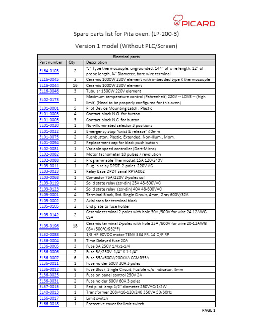
LP-200-3 Pita Oven 零件清单说明书
ME84-0011 TUN31904 TUN31920 VE68-0036
FO75-0015
FO75-00XX
Qty 2 6 2.9 1
2.63 1
13
2 2 4 2 2 1 4 1 1 1
2.1
15 1 1 1
A/R
A/R
Mechanical parts Description Split chain link #35 129033/012 Main Conveyor graphite bushing #40 riveted rollers Chain (Sold per Foot length) Connecting link #40 #35 riveted rollers Chain (Sold per Foot length) Connecting link #35 Chain Z-40-P76.2 (over size roller flange type) A2 attachment ( LP200 ) P/M SLEEVE .502 X .753 X 3/4 Pillow block with bearing UC202 5/8" (pita) Y HUB 1'' kw & 2ss (pita) 4" white nylon pivoting wheel with brake 330LBS (pita) 4" white nylon pivoting wheel 330LBS (pita) Sprocket #35, type B, 12 teeth x 5/8 Sprocket for metallic conveyor belt #1245 Conveyor Oven Sprocket #35 type B 48 teeth x 3/4" (with key way + set screw) Sprocket #40 type B 26 teeth x 3/4" (with key way + set screw) Sprocket #40 type B 13 teeth x 3/4" (with key way + set screw) Stainless steel mesh conveyor 48x0.50,22.00w,9sp,sle,ss(pita) (Sold per Foot length) Hard stone brick 9” x 4” x 1¼” Tempered glass door 6 '' x 20 '' x 10mm (pita) Tempered glass door 17 '' x 23-7/8 '' x 10mm (pita) Small fan 4 "dia 230v 110cfm (axial fan) White food grease high temperature Haynes 500 (10 cartridges (tube) x 14 Oz / cs) (Chain grease for #35 and #40 chains) (Can be sold as a single cartridge as 0.1 Qty) Food grade high temperature smokeless oil for main conveyor (chain oil for Z-40-P76.2 chain)
变频器品牌型号大全

变频器品牌型号多年收藏整理的变频器说明书,全部为高清PDF版本,有需要的请发邮件到*****************索取!说明书部分目录如下:1.台安(TAIAN)变频器说明书E2 N2 V2 SV300 N310 S310 EV300 K1/N1 K200/K400 9300JS E2-EN 2.台达(DELTA)变频器说明书VFD-A VFD-B VFD-E VFD-F VFD-G VFD-L VFD-MVFD-S VFD-V VFD-VE VFD-EL VFD-B/P VFD-VL3.英威腾(INVT)变频器说明书G9/P9/GS/GL CHE CHF CHV CHV110 CHV160 CHV1804.汇菱(HUILING)变频器说明书 H30005.信捷(XINJE)变频器说明书 V5/F56.凯迪华能变频器说明书 CD20007.酷马(QMA)变频器说明书 Q5000 Q7000 Q90008.黎升同步控制器说明书 SAD240 SAD280 SAD280i9.三品(SANPIN)变频器说明书 SKJ SPRQ-33310.能士(NSA)变频器说明书 NSA20 NSA8011.台凌(TAILING)变频器说明书 TL80 TL100 TL100H12.力普变频器说明书 LP10013.安普(AMPLE)变频器说明书 AMP100014.誉强(YUQIANG)变频器说明书YQ3000-M YQ3000-A YQ3000-G YQ3000-A7(上) A7(中) A7(下)15.格立特(GREAT)变频器说明书VF10 VF11 VF15 VC300 VC3100 VC320016.RICH(利佳/艾瑞克)变频器说明书EI-MINI EI-450EI-450M EI-500EI-550EI-600EI-700EI-7001 EI-8001 EI Super N17.汇川(INOVANCE)变频器说明书MD021 MD280 MD300 MD300A MD320 MD33018.远川(YCDZ)变频器说明书YC-G YC-P TE580 软启动器19.紫日(CHZIRI)变频器说明书ZVF7 ZVF9 ZVF9V ZVF11 软启动20.森兰(SENLAN)变频器说明书SB12 SB40 SB50 SB60/61 SB60+/61+ SB61Z SB61Z+ SB70 SB80 SB100 SB200 BT12 BT4021.安邦信(AMBITION)变频器说明书G7/P9 G9/P9 V11 G11 E11 Z9/Z11 HVI22.普传(POWTRAN)变频器说明书168 PI97G PI7000/7100 PI7600/7800 PI766023.日业(SUNYE)变频器说明书。
3LP01SS中文资料

IT00082
Forward Transfer Admittance, yfs -- S
7 5 3 2
VDS= --10V
Static Drain-to-Source On-State Resistance, RDS(on) -- Ω
-I D=
A 30m
,
= -V GS
2.5
V
25°C
2 Ta= -5°C
Electrical Characteristics at Ta=25°C
Parameter Drain-to-Source Breakdown Voltage Zero-Gate Voltage Drain Current Gate-to-Sourse Leakage Current Cutoff Voltage Forward Transfer Admittance Symbol V(BR)DSS IDSS IGSS VGS(off) yfs Conditions ID=--1mA, VGS=0 VDS=-30V, VGS=0 VGS=± 8V, VDS=0 VDS=-10V, ID=--100µA VDS=-10V, ID=--50mA Ratings min --30 --10 ± 10 --0.4 80 110 --1.4 typ max Unit V µA µA V mS
unit : mm 2179
[3LP01SS]
1.4
0.3
Low ON-resistance. Ultrahigh-Speed Switching. 2.5V drive.
0.25
0.1
3
0.8 1.4
0.2
0.3
1 0.45
2
1 : Gate 2 : Source 3 : Drain
- 1、下载文档前请自行甄别文档内容的完整性,平台不提供额外的编辑、内容补充、找答案等附加服务。
- 2、"仅部分预览"的文档,不可在线预览部分如存在完整性等问题,可反馈申请退款(可完整预览的文档不适用该条件!)。
- 3、如文档侵犯您的权益,请联系客服反馈,我们会尽快为您处理(人工客服工作时间:9:00-18:30)。
1.6 0.5 0.5
1 2
3
0.1
0 to 0.1
0.1 MIN
1 : Gate 2 : Source 3 : Drain SANYO : SMCP
0.75 0.6
3LP03S P.G 50Ω S
--0.30
ID -- VDS
0V
V
--3. 5
--0.50
ID -- VGS
Ta= --25 °
75° C 25° C
Ambient Temperature, Ta -- °C
IT07656
No. A0010-2/4
元器件交易网
3LP03S
1.0
yfs -- ID
VDS= --10V
Forward Transfer Admittance, yfs -- S
7 5 3 2
--1.0 7 5 3 2 --0.1 7 5 3 2 --0.01 7 5 3 2
Ta=7 5°C 25°C --25°C
--0.6 --0.8
°C
Source Current, IS -- A
--1.0
--1.2
--1.4
Diode Forward Voltage, VSD -- V
IT07658
SW Time -- ID
VDS= --15V VGS= --4V
Ciss, Coss, Crss -- pF
C
VDS= --10V
--3.5
Drain-to-Source Voltage, VDS -- V
5.0 4.5
IT07653
RDS(on) -- VGS
Gate-to-Source Voltage, VGS -- V
4.0 3.5 3.0 2.5 2.0 1.5 1.0 0.5 0 --60
IT07654
元器件交易网
3LP03S
Continued from preceding page.
Parameter Turn-ON Delay Time Rise Time Turn-OFF Delay Time Fall Time Total Gate Charge Gate-to-Source Charge Gate-to-Drain “Miller” Charge Diode Forward Voltage Symbol td(on) tr td(off) tf Qg Qgs Qgd VSD Conditions See specified Test Circuit. See specified Test Circuit. See specified Test Circuit. See specified Test Circuit. VDS=--10V, VGS=-4V, ID=--250mA VDS=--10V, VGS=-4V, ID=--250mA VDS=--10V, VGS=-4V, ID=--250mA IS=--250mA, VGS=0V Ratings min typ 9.5 5 15 13 0.8 0.3 0.2 --0.9 --1.2 max Unit ns ns ns ns nC nC nC V
(*1) : Note, when designing a circuit using this product, that it has a gate (oxide film) protection diode connected only between its gate and source.
SANYO Electric Co.,Ltd. Semiconductor Company
TOKYO OFFICE Tokyo Bldg., 1-10, 1 Chome, Ueno, Taito-ku, TOKYO, 110-8534 JAPAN
81005PE MS IM TA-101200 No. A0010-1/4
Electrical Characteristics at Ta=25°C
Parameter Drain-to-Source Breakdown Voltage Zero-Gate Voltage Drain Current Gate-to-Source Leakage Current Cutoff Voltage Forward Transfer Admittance Static Drain-to-Source On-State Resistance Input Capacitance Output Capacitance Reverse Transfer Capacitance Symbol V(BR)DSS IDSS IGSS VGS(off) yfs RDS(on)1 RDS(on)2 RDS(on)3 Ciss Coss Crss Conditions ID=--1mA, VGS=0V VDS=-30V, VGS=0V VGS=--8V, VDS=0V VDS=-10V, ID=--100µA VDS=-10V, ID=--120mA ID=--120mA, VGS=--4V ID=--60mA, VGS=--2.5V ID=--10mA, VGS=--1.5V VDS=-10V, f=1MHz VDS=-10V, f=1MHz VDS=-10V, f=1MHz Ratings min --30 --1 --1 --0.4 0.24 0.4 1.5 2.0 4.0 40 8 4.5 1.9 2.8 8.0 --1.4 typ max Unit V µA µA V S Ω Ω Ω pF pF pF
--60mA
--6 I D=
, VG 0mA
--2 S=
.5V
I D= --
A, 120m
= --4. VGS
0V
--2
--3
--4
--5
--6
--7
--8
--9--10--40 Nhomakorabea--20
0
20
40
60
80
100
120
140
Gate-to-Source Voltage, VGS -- V
IT08162
VGS= --1.5V
--0.10
--0.05 0 0 --0.1 --0.2 --0.3 --0.4 --0.5 --0.6 --0.7 --0.8 --0.9 --1.0 0 0 --0.5
25°
--0.05
C
--0.10
--1.0
Ta= 75° C --25 °C
--0.15
--1.5
--2.0
Drain Current, ID -- A
Drain-to-Source Voltage, VDS -- V
--4.0 --3.5 --3.0 --2.5 --2.0 --1.5 --1.0 --0.5 0 0
VGS -- Qg
RDS(on) -- ID
Static Drain-to-Source On-State Resistance, RDS(on) -- Ω
Specifications
Absolute Maximum Ratings at Ta=25°C
Parameter Drain-to-Source Voltage Gate-to-Source Voltage (*1) Drain Current (DC) Drain Current (Pulse) Allowable Power Dissipation Channel Temperature Storage Temperature Symbol VDSS VGSS ID IDP PD Tch Tstg PW≤10µs, duty cycle≤1% Conditions Ratings --30 --10 --0.25 --1 0.15 150 --55 to +150 Unit V V A A W °C °C
Package Dimensions
unit : mm 7027-004
1.6 0.8
Switching Time Test Circuit
VIN 0V --4V VDD= --15V
0.4
0.2
0.4
0.3
VIN PW=10µs D.C.≤1% G D
ID= --120mA RL=125Ω VOUT
元器件交易网
Ordering number : ENA0010
3LP03S
P-Channel Silicon MOSFET
3LP03S
Features
• • • •
General-Purpose Switching Device Applications
Low ON-resistance. Ultrahigh-speed switching. 2.5V drive. High ESD Voltage (TYP 300V) [Built-in one side diode for protection between Gate-to-Source].
RDS(on) -- Ta
Ta=25°C
Static Drain-to-Source On-State Resistance, RDS(on) -- Ω
4.0 3.5 3.0 2.5 2.0 1.5 1.0 0.5 0 0 --1
ID= --120mA
Static Drain-to-Source On-State Resistance, RDS(on) -- Ω
Ciss, Coss, Crss -- VDS
Switching Time, SW Time -- ns
2
50
td (off) tf
10
40
Ciss
td(on)
7 5