AVGA476M06C12T-F中文资料
艾膈xStorage家型单相,3.6kW,4.2kWh,AC耦合,灰色 蜂窝模式,PV6说明书
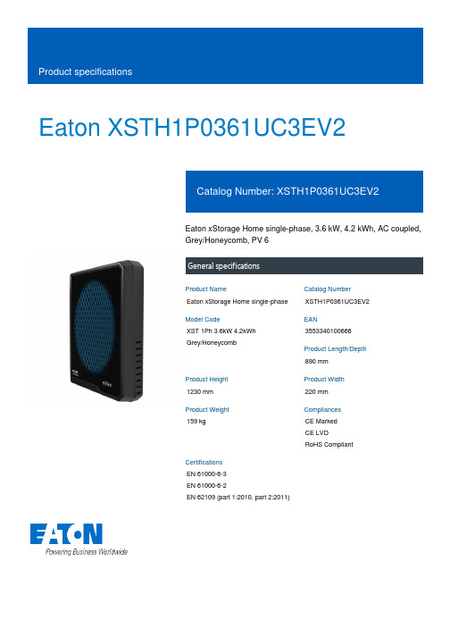
Eaton XSTH1P0361UC3EV2Eaton xStorage Home single-phase, 3.6 kW, 4.2 kWh, AC coupled, Grey/Honeycomb, PV 6General specificationsEaton xStorage Home single-phase XSTH1P0361UC3EV2XST 1Ph 3.6kW 4.2kWh Grey/Honeycomb3553340100666890 mm1230 mm 220 mm 159 kgCE Marked CE LVD RoHS CompliantEN 61000-6-3 EN 61000-6-2EN 62109 (part 1:2010, part 2:2011)Product NameCatalog Number Model CodeEANProduct Length/Depth Product Height Product Width Product Weight Compliances Certifications0.99 (Grid-Tie), 0.8 (ind) - 0.8 (cap) (Grid Tie-PF regulation, Off-Grid)3,6 kW17.4 A230V97%Residual current circuit breaker (RCCB)Overload-/temperature protectionShort-circuit protectedBuilt-in batteryWith data loggingEthernetWLANEmergency power compatible3600 VA550 V20 AIP20Power metering of critical loads and PV production Eaton xstorage Home Brochure enxStorage Home BrochurexStorage Home Product team guidelinesxStorage Home Installation manualEaton xStorage Home Quick Start Guide xStorage Home User Interface Manual xStorage Home User manualEaton xStorage Home Safety GuidelinesHow to onboard xStorage Home into the Cloud xStorage Home - Technical data sheetOutput power factorPower rangeAC current - maxAC inputEfficiency (PV to grid) - max Fitted with:Nominal output powerDC voltage on PV input - max Input Current on PV Input – Max Degree of ProtectionLED indicator colorMetering capability BrochuresCase studiesManuals and user guidesMultimediaTechnical data sheetsGreen (ON): Normal status. Red (ON): Fault status. Inverter is unable to connect to the grid.Green (Blinking): Communication activitySpecial featuresThe xStorage Home system offers three different power inverter ranges.Nominal DC Operating Voltage – Max550 VCoolingNatural airflowStorage temperature - max40 °CTopologyTransformerlessBattery nominal capacity4,2 kWhProtective classIAC wiring systemsSingle phase/N/PE, TN, TT, IT (additional fuse or CB required)Relative humidity - min5 %C/D DC current - Max70 ANominal AC output current15.6 AStandby losses< 10WStorage temperature - min-10 °CDC battery voltage - min74.4 VOver voltage categoryOVC II (PV and Battery), OVC III (AC grid/load)PhaseSingle phaseOperating temperature - min0 °CRelative humidity - maxEfficiency (Battery to AC) - Max>90%Grid integrationDC and AC coupledNumber of MPPT Trackers2Noise level35 dB (indoor application)Rated MPP-voltage – min240 VMaterial coverPlasticNominal DC Operating Voltage – Min 100 VPower consumption3.6 kWOperating temperature - max30 °CHazard substance restrictionLead free, compliance with RoHS GP2Initial feeding voltage150 VProtocolHTTPAPIRESTMPPT efficiency> 99%Recommended PV power3 kWp - 7 kWpSolar DC switchYesNominal AC grid voltage230 V (Grid-Tie), 230 V ± 3 % (Off-Grid)DC battery voltage - max98.4 VEaton Corporation plc Eaton House30 Pembroke Road Dublin 4, Ireland © 2023 Eaton. All rights reserved. Eaton is a registered trademark.All other trademarks areproperty of their respectiveowners./socialmedia35 A90 V< 3%AC Synchronized operation 50 Hz / 60 Hz ± 1 Hz 2000 m Standard550 VBattery voltage rating Total Harmonic Distortion (THD)Nominal frequencyAltitude Display Rated MPP-voltage – max。
18 G3VM-62C1 F1 MOS FET 开关电路器件说明书

G3VM-62C1/F1 MOS FET RelaysAnalog-switching MOS FET Relays forHigh Switching Currents, with DielectricStrength of 2.5 kVAC between I/O.•New 2-channel model included in the 60-V load voltageseries.•Switches minute analog signals.•Dielectric strength of 2,500 Vrms between I/O.•Surface-mounting models included in series.RoHS compliant!■Application Examples•Measurement devices•Security systemsNote:The actual product is marked differently from the imageshown here.■List of Models■DimensionsNote:All units are in millimeters unless otherwise indicated.■■PCB Dimensions (Bottom View)Contact form Terminals Load voltage (peak value)Model Number per stick Number per tape DPST-NO PCB terminals60 VAC G3VM-62C150---Surface-mountingterminalsG3VM-62F1G3VM-62F1(TR)---1,500G3VM-62C1G3VM-62F1Note:ly from the imageshown here.Note:The actual productis marked different-ly from the imageshown here.G3VM-62C1G3VM-62C1G3VM-62C1/F1G3VM-62C1/F1■Absolute Maximum Ratings (Ta = 25°C)■Electrical Characteristics (Ta = 25°C)■Recommended Operating ConditionsUse the G3VM under the following conditions so that the Relay will operate properly.■Engineering DataLoad Current vs. Ambient TemperatureG3VM-62C1(F1)■Safety PrecautionsRefer to “Common Precautions” for all G3VM models.ItemSymbol Rating Unit Measurement ConditionsInputLED forward currentI F 50mARepetitive peak LED forward currentI FP 1A 100 µs pulses, 100 pps LED forward current reduction rate∆ I F /°C −0.5mA/°C Ta ≥ 25°CLED reverse voltageV R 5V Connection temperatureT j 125°C OutputOutput dielectric strength V OFF 60V Continuous load current I O 500mA ON current reduction rate ∆ I ON /°C −5.0mA/°C Ta ≥ 25°CConnection temperatureT j 125°C Dielectric strength between input and output (See note 1.)V I-O 2,500Vrms AC for 1 minOperating temperature T a −40 to +85°C With no icing or condensation Storage temperature T stg −55 to +125°CWith no icing or condensation Soldering temperature (10 s)---260°C10 s Note:1.The dielectric strength between the input andoutput was checked by applying voltage be-tween all pins as a group on the LED side and all pins as a group on the light-receiving side.ItemSymbol Mini-mum Typical Maxi-mum UnitMeasurement conditions InputLED forward voltage V F 1.0 1.15 1.3V I F = 10 mA Reverse currentI R ------10µA V R = 5 V Capacity between terminals C T ---30---pF V = 0, f = 1 MHz Trigger LED forward currentI FT --- 1.63mA I O = 500 mA OutputMaximum resistance with output ON R ON --- 1.0 2.0ΩI F = 5 mA, I O = 500 mA Current leakage when the relay is openI LEAK ------ 1.0µA V OFF = 60 V Capacity between I/O terminals C I-O ---0.8---pF f = 1 MHz, Vs = 0 V Insulation resistance R I-O 1,000------M ΩV I-O = 500 VDC, RoH ≤ 60%Turn-ON time tON ---0.8 2.0ms I F = 5 mA, R L = 200 Ω, V DD = 20 V (See note 2.)Turn-OFF timetOFF---0.10.5ms Note:2.Turn-ON and Turn-OFFTimesItemSymbol MinimumTypicalMaximumUnitOutput dielectric strength V DD------48V Operating LED forward current I F 57.525mA Continuous load current I O ------500mA Operating temperatureT a− 20 ---65°CCommon Precautions!WARNINGBe sure to turn OFF the power when wiring the Relay, other-wise an electric shock may be received.!WARNINGDo not touch the charged terminals of the SSR, otherwise an electric shock may be received.!CautionDo not apply overvoltage or overcurrent to the I/O circuits of the SSR, otherwise the SSR may malfunction or burn.!CautionBe sure to wire and solder the Relay under the proper soldering conditions, otherwise the Relay in operation may generate ex-cessive heat and the Relay may burn.Typical Relay Driving Circuit ExamplesUse the following formula to obtain the LED current limiting resis-tance value to assure that the relay operates accurately.Use the following formula to obtain the LED forward voltage value to assure that the relay releases accurately.Protection from Surge Voltage on the Input TerminalsIf any reversed surge voltage is imposed on the input terminals, insert a diode in parallel to the input terminals as shown in the fol-lowing circuit diagram and do not impose a reversed voltage value of 3V or more.Surge Voltage Protection Circuit ExampleProtection from Spike Voltage on the Output TerminalsIf a spike voltage exceeding the absolute maximum rated value isgenerated between the output terminals, insert a C-R snubber or clamping diode in parallel to the load as shown in the following circuit diagram to limit the spike voltage.Spike Voltage Protection Circuit ExampleUnused Terminals (6-pin models only)Terminal 3 is connected to the internal circuit. Do not connect anything to terminal 3 externally.Pin Strength for Automatic Mountingn order to maintain the characteristics of the relay, the force imposed on any pin of the relay for automatic mounting must not exceed the following.In direction A: 1.96 NIn direction B: 1.96 NLoadTransistor10 to 100 kΩLoadR1 =V CC− V OL− V F (ON) 5 to 20 mAV F (OFF) = V CC− V OH < 0.8 VLoad ConnectionDo not short-circuit the input and output terminals while the relay is operating or the relay may malfunction.Solder MountingPerform solder mounting under the following recommended con-ditions to prevent the temperature of the Relays from rising.<Flow Soldering>Through-hole Mounting (Once Only)Note:We recommend that the suitability of solder mounting be verified under actual conditions.<Reflow Soldering>Surface Mounting DIP or SOP Packages (Twice Max.) Surface Mounting SSOP Packages (Twice Max.)Note: 1.We recommend that the suitability of solder mounting be verified under actual conditions.2.Tape cut SSOPs are packaged without humidity resis-tance. Use manual soldering to mount them.Manual Soldering (Once Only)Manually solder at 350°C for 3 s or less or at 260°C for 10 s or less.SSOP Handling Precautions<Humidity-resistant Packaging>Component packages can crack if surface-mounted components that have absorbed moisture are subjected to thermal stress when mounting. To prevent this, observe the following precau-tions.1.Unopened components can be stored in the packaging at 5to 30°C and a humidity of 90% max., but they should be used within 12 months.2.After the packaging has been opened, components can bestored at 5 to 30°C and a humidity of 60% max., but they should be mounted within 168 hours.3.If, after opening the packaging, the humidity indicator turnspink to the 30% mark or the expiration data is exceeded, bake the components while they are still on the taping reel, and use them within 72 hours. Do not bake the same com-ponents more than once.Baking conditions: 60±5°C, 64 to 72 hExpiration date: 12 months from the seal date(given on the label)4. f the same components are baked repeatedly, the tapedetachment strength will change, causing problems when mounting. When mounting using dehumidifying measures, always take countermeasures against component damage from static electricity.5.Do not throw or drop components. If the laminated packag-ing material is damaged, airtightness will be lost.6.Tape cut SSOPs are packaged without humidity resistance.Use manual soldering to mount them.AC ConnectionDC Single Connection DC Parallel Connection LoadLoadLoadLoadSolder type Preheating SolderingLead solderSnPb150°C60 to 120 s230 to 260°C10 s max.Lead-free solderSnAgCu150°C60 to 120 s245 to 260°C10 s max.Solder type Preheating SolderingLead solderSnPb140→160°C60 to 120 s210°C30 s max.Peak240°C max.Lead-free solderSnAgCu180→190°C60 to 120 s230°C30 to 50 sPeak260°C max.Solder type Preheating SolderingLead solderSnPb140→160°C60 to 120 s210°C30 s max.Peak240°C max.Lead-free solderSnAgCu150→180°C120 s max.230°C30 s max.Peak250°C max.。
超低电压大电流直流电子负载

1.2.
主要特点 ............................................................................................................ 1
1.3.
主机面板介绍 .................................................................................................... 2
2.6.2. 控制连接 ............................................................................................................ 6
2.6.3. 采样连接 ............................................................................................................ 6
3.1.
控制模式 ............................................................................................................ 8
3.2.
恒电流测试功能(CC) ................................................................................... 8
2.6.
连接方式 ............................................................................................................ 5
航嘉电源2013年产品手册
C:\Documents and
外观结构图:Settings\liyis\桌
C:\Documents and
线材接口图(仅供参考,以实物为准):Settings\liyis\桌
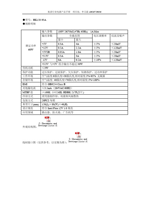
航嘉行业电源产品手册 项目处:李义霜 18926759036
●型号:HK250-93FP
●规格明细
输入参数 90V-265VAC(47Hz-63Hz) 3A Max
≤3W
过压保护、过流保护、欠压保护、短路保护、过功率保护
空气温度:0摄氏度~40摄氏度,相对湿度:5%~85% 无凝露
空气温度:-40摄氏度~70摄氏度,相对湿度:5%~95%
符合 GB9254 Class B
≤3.5mA(264VAC/60HZ)
≥100K 小时.MIL-HDBK-217F(25℃)
冷却方式
采用强制冷却、双滚珠风扇散热
包装方式
20PCS 每箱
典型尺寸(mm) 150(L)×80(W)×40(H)
设计规范
符合 Intel Flex 12V 1.0 规范
应用领域
路由器、防火墙、广告机等
纹波及噪声
≤50mV ≤120mV ≤50mV ≤50mV ≤120mV
C:\Documents and
≤3W
过压保护、过流保护、欠压保护、短路保护、过功率保护
空气温度:0摄氏度~50摄氏度,相对湿度:5%~95% 无凝露
空气温度:-40摄氏度~70摄氏度,相对湿度:5%~100%
符合 GB9254 Class B
≤3.5mA(264VAC/60HZ)
≥100K 小时.MIL-HDBK-217F(25℃)
C:\Documents and
IS104GPS-2F 6-port Gigabit managed PoE switch User

User ManualIS104GPS-2F6-port Gigabit managed PoE switchInstallation Manual Introduction<User Manual>mainly introduces the hardware features, installation methods,and precautions during the installation of IS104GPS-2F.This manual includes the following sections:Chapter1:Product introduction.Briefly describe the basic functions and features of the switch,detailed hardware and software specifications and appearance information.Chapter2:Hardware Connections.Guide the connection of switch with other devices and precautions.Chapter3:Product Installation.Guide the hardware installation method and precautions.Chapter4:Product Packaging and Use Recommendations.Chapter1Product Introduction1.1Product introductionThe IS104GPS-2F is a6-port Gigabit-managed industrial PoE switch that provides4Gigabit ports and2Gigabit SFP ports.Each PoE port can provide up to46W for IEEE802.3af/at compatible powered devices(PDs).It is especially suitable for applications where AC power is not easily available or high wiring costs.It support EMC industrial grade4protection;corrugated high-strength aluminum profile housing,IP40grade,low power design,seismic rail mounting,-40°C-75°C operating temperature, can work in harsh environments;IS104GPS-2F also supports Apollo cloud one-stop management platform for status checking and management monitoring,to make it become a reliable solution for Intelligent transportation,video surveillance and other harsh industrial environments.21.2FeaturesFull Gigabit Ethernet port4full Gigabit RJ45PoE network port,and2Gigabit SFP ports, breaking the traditional100M limitation,data transmission will not stuckBroadcom high performance industrial grade chip for more stable performanceBroadcom high-performance industrial-grade chips that dramatically increase network data processing ratesPowerful working environmentEMC industrial grade4protection;corrugated high-strength aluminum profile housing,IP40grade,low power design,seismic rail mounting,-40°C-75°C operating temperature,can work in harsh environments3Support Apollo cloud platform one-stop management Support cloud platform to visualize management of switches and attached power devices,making operation and maintenance management easier1.3Software and hardware specificationsHardware specificationChipBroadcom high performance chipFlash16MBRAM64MBDDRPort410/100/1000M RJ45Port21000M SFP PortPoE Power supply 410/100/1000MbpsRJ45Port support 802.3af/atPoE power supplyThe maximum power per port is46W4Indicator 6Link/Act indicator4POEindicatorALM Alarm indicatorP1、P2Power Indicator1SYS indicatorPerformance Forward mode:store and forward Backplane bandwidth:12Gbps Packet forwarding rate:8.9Mpps Support8K MAC address table depthStandard protocol IIEEE802.3:Ethernet Media Access Control (MAC)ProtocolIEEE802.3i:10BASE-T EthernetIEEE802.3u:100BASE-TX Fast EthernetIEEE802.3ab:1000BASE-T Gigabit Ethernet IEEE802.3z:1000BASE-X Gigabit Ethernet (optical fiber)5IEEE802.3ad:Standard method for performing link aggregationIEEE802.3x:Flow ControlIEEE802.1p:LAN Layer2Qos/Cos protocol for traffic prioritization(multicast filtering)IEEE802.1q:VLAN Bridge OperationIEEE802.1d:STP spanning treeIEEE802.1s:MSTP Spanning TreeIEEE802.1w:RSTP Spanning TreeIEEE802.3afIEEE802.3atIndustry Standard EMI:FCCCFR47Part15,EN55022/CISPR22, Class AEMS:IEC61000-4-2(ESD):±8kV(contact),±15kV6(air)IEC61000-4-3(RS):10V/m(80MHz-2GHz)IEC61000-4-4(EFT):Power Port:±4kV;Data Port:±2kVIEC61000-4-5(Surge):Power Port:±2kV/DM,±4kV/CM;Data Port:±6kVIEC61000-4-6(CS):3V(10kHz-150kHz);10V (150kHz-80MHz)IEC60068-2-6(Vibration)IEC60068-2-27(Shock)IEC60068-2-32(Free Fall)Operation environment Working temperature:-40~75°CStorage temperature:-40to75°CRelative humidity:5%to95%(no condensation)7Certification CE,FCC,RoHSMean timebetweenfailures(MTBF)100,000hrsWarranty3yearsLightningprotectionNetwork port:±6KV power port:±4KV ESD Contact:±8KV Air:±15KVPhysical specification Input:48-56VDCHousing:IP40grade protection,corrugated high strength metal housingInstallation:DIN rail mountingSize:163mm×46.5mm×110mm,Weight:1kg8Software specification101112131.4AppearanceIndicator StatusDescriptionP1、P2On The corresponding power supply working normally.Off The corresponding power supply is not connected or working abnormal.SYS Blink System is running normally14ingOff/ alwa ys brig ht System operation is abnormal/start unsuccessfulALM On Alarm start upOff Alarm not triggeredLink/ACT F1-F4BlinkingSFP port is working normalOff SFP port is working abnormally/port is not connected1516Chapter 2.Hardware Connection2.1Connect to RJ45portUse the network cable to connect the switch to the RJ45port of network device.Normally,the switch's downlink port has POE power supply enabled by default.It can support POE power supply to AP ,bridge,network camera and other PDs which comply with IEEE802.3af and IEEE802.3atstandards.2.2Connect to the SFP portThe SFP port of the IS104GPS-2F supports only Gigabit fiber modules.It is recommended to use standard SFP module products. The process of installing a fiber module on a switch is as follows:1.Grasp the fiber module from the side and insert it smoothly along the SFP port slot of the switch until the fiber module is in close contact with the switch;2.Confirm the Rx and Tx ports of the fiber module when connecting.Insert one end of the fiber into the Rx and Tx ports to ensure that the Tx and Rx ends of the interface are correctly connected,and the other end of the fiber is connected to another device.3.After power-on,check the status of the corresponding indicator.If the indicator is on,the link is up.If not,please check the line and confirm that the peer device is enabled.1718Attention:It is not allowed to excessively bend the fiber,and its radius of curvature should be no less than 10cm;Ensure the cleanliness of the fiber end face;Please do not look directly into the fiber optic connector with your eyes,as this may cause eye damage.2.3Check before power-onCheck that the power supply of the power outlet meets the switch specifications.Check that the power supply,switch,and rack are properly grounded.Check whether the switch is connected to other network devices.2.4Device initializationThe switch will automatically initialize after the power is turnedonand the power switch is turned on.The indicator light will appear as follows:After the power is turned on,the power indicator remains steady, the SYS light enters the blinking state,and the system runs normally.The indicator of each port indicates the connection status of each port,indicating that the switch has started to work normally.Chapter3,Product InstallationBefore installation,confirm the operating environment of the equipment:power supply voltage,installation space,installation method,etc.Please carefully confirm the following installation requirements:-Check for cables and connectors required for19installation♦-Check whether the cable is in place(not more than100m)according to reasonable configuration requirements.♦-The product does not provide mounting components,the user must prepare the components of the selected installation type:screws,nuts and tools to ensure reliable installationPower requirements:12-56V DC(12-48V nonsupportPoE,support date exchange only)Environmental requirements:Working temperature:-40~75°CStorage temperature:-40to75°CRelative humidity:5%to95%(no condensation) Power input20215pin 5.08mmterminalInput range:12-56VDCP1&P2dual redundant power supply,Support reverse connection protectionGround protectionGroundprotectionConnect to groundRail mountingChapter4,Packing list and use recommendations 4.1Product packagingItem Quantity Description Switch1set\Phoenix terminal1*5,1*2eachper one unit Connect to power and alarm switchWarranty card1piece For after-sales maintenance User Manual1copy Used to guide users to installswitches4.2Recommendations1.For safety reasons,non-professionals should not open the product casing;2.Pay attention to the danger of strong electricity and safe protection when the product is powered on;223.Do not use the switch in a humid environment to prevent water from entering the fuselage through the casing,resulting in damage to the machine;4.In the state of power-on of the product,please do not plug and unplug the cable if non special case;5.Please do not place heavy objects on the switch to avoid accidents;6.It is recommended to use the switch indoors.It is recommended to add a waterproof box when using it outdoors. Note:The pictures in the manual are for reference only,whichever is subject to the actual product.23。
476h钽电容

476h钽电容476h钽电容是一种常见的电子元件,用于电路中的储能和滤波等功能。
钽电容具有优良的电容性能和稳定性,因此在各种电子设备中得到广泛应用。
钽电容的名称中的476h代表了其电容量的大小。
电容量是电容器存储电荷的能力,通常以法拉(F)为单位表示。
而钽电容的电容量为476微法(μF),这是一个相对较大的数值,意味着它能够存储较多的电荷,具有较大的储能能力。
钽电容的电容量大小对于电路的性能和稳定性有着重要的影响。
在电路中,钽电容常用于滤波电路中,能够过滤掉电源中的高频噪声,使得电路的工作更加稳定。
此外,钽电容还可以用于储能电路,将电能储存起来,并在需要时释放出来。
这在一些需要瞬间大电流输出的电路中非常重要,例如电源启动电路、电机驱动电路等。
钽电容与其他类型的电容器相比具有一些明显的优点。
首先,钽电容器的体积相对较小,能够在有限的空间内提供较大的电容量。
这使得钽电容在一些小型电子设备中得以广泛应用,如手机、平板电脑等。
其次,钽电容具有较低的ESR(等效串联电阻),能够提供更好的电流响应特性。
这对于需要高频响应的电路非常重要,如无线通信设备、高速数据传输设备等。
钽电容的制作材料是钽,这是一种稀有金属。
钽具有良好的化学稳定性和耐腐蚀性,能够在各种恶劣环境下工作。
此外,钽还具有良好的导电性能和热传导性能,能够有效地传递电荷和散热,提高钽电容的工作效率和稳定性。
然而,钽电容也存在一些限制和注意事项。
首先,钽电容相对于其他类型的电容器来说价格较高,这增加了电路成本。
其次,钽电容对于过电压和过电流比较敏感,一旦超出其额定值,可能会导致电容器短路、烧毁甚至爆炸。
因此,在使用钽电容时,需要仔细选择合适的工作电压和电流,并做好电路保护措施,以确保电容器的安全可靠运行。
476h钽电容是一种常见的电子元件,具有较大的电容量和稳定性。
它在电路中承担着储能和滤波等重要功能,被广泛应用于各种电子设备中。
钽电容的优点包括体积小、ESR低等,但也需要注意其价格较高和对过电压、过电流的敏感性。
FS100R12KT3中文资料

,-. m,o U U 2W W ,:
2 3- ( U,A.W ,-. ( ,
200 180 160 140 120 100 80 60 40 20 0
A5ZZ ( :I O: ,-. ( K
25
20
" m#[o
5 6 7 8 9 10 11 12
Vorläufige Daten preliminary data
Diode-Wechselrichter / diode-inverter
Höchstzulässige Werte / maximum rated values
8 1 1+ 8 = 3d $ > 2 > $ 2 $ 2 # # 9(0# ,; ( ,: 9 ( 0 # : %&' ( 0 )*+ $ %&' ( )*+ ,;;< 3c 3c;< 3d # ,: %&' ( )*+ ,: %&' ( 0 )*+ ,c 0:K) 0:K) 0 0 0 : : ): I: : 0I) # D :0) 0 0 , 7 7 7d
"54 0 : "5ZZ 0 : 3/?Jb: K
7
2 $
$
8
! +
2 \
2
3 @E # > 2 # :`
!C@
1
元器件交易网
Technische Information / technical information
IGBT-Module IGBT-modules
7MBP100TEA060资料

Short operating
Collector-Emitter voltage *1
Collector current
DC
Inverter
1ms
Duty=72.3% *2
Collector power dissipation One transistor *3
Collector current
DC
元器件交易网
7MBP100TEA060
Econo IPM series
600V / 100A 7 in one-package
Features
· Temperature protection provided by directly detecting the junction temperature of the IGBTs
Symbol
Condition
Min.
Brake
Inverter
Collector current at off signal input Collector-Emitter saturation voltage
Forward voltage of FWD
Collector current at off signal input Collector-Emitter saturation voltage
Symbol Iccp ICCN Vin(th)
Input zener voltage
VZ
Alarm signal hold time
tALM
Current limit resistor
RALM
Condition Switching Trequency : 0 to 15kHz Tc=-20 to 125°C Fig.7 ON OFF Rin=20k ohm Tc=-20°C Fig.2 Tc=25°C Fig.2 Tc=125°C Fig.2 Alarm terminal
- 1、下载文档前请自行甄别文档内容的完整性,平台不提供额外的编辑、内容补充、找答案等附加服务。
- 2、"仅部分预览"的文档,不可在线预览部分如存在完整性等问题,可反馈申请退款(可完整预览的文档不适用该条件!)。
- 3、如文档侵犯您的权益,请联系客服反馈,我们会尽快为您处理(人工客服工作时间:9:00-18:30)。
Specifications–40 °C to +105 °C6.3, 10, 16, 25, 35, 50, 63 Vdc 0.1µF to 4700 µF±20% @ 120 Hz and +20 °CFor Filtering, Bypassing and Power Supply Decoupling with High Capacitance RequirementsHighlights• +105 °C, Up to 2000 Hours Load Life • Capacitance Range: 0.1 µF to 4700 µF • Voltage Range: 6.3 Vdc to 63 VdcOperating Temperature: Rated Voltage:Capacitance:Capacitance Tolerance:Leakage Current (at 20 ºC):Dissipation Factor:(Tan δ at 120 Hz, 20 ºC )Low TemperatureCharacteristic (at 120 Hz):Shelf LifeTest: Type AVGA Capacitors are rated for 2000 hours at 105 ºC and up to 63 Vdc. They are ideal for high density PC board packaging. The Type AVGA offers a low in-place-cost for a high quality performer. The vertical cylindrical cases facilitate automatic mounting and reflow soldering into the same footprint of like-rated tantalum capacitors except without the need for voltage derating. Type AVGA is RoHS compliant.6.3 – 63 V4 – 10 ØI = 0.01 CV or 3 µA, whichever is greater, after 2 minutes at +20 ºC 12.5 ~ 16 ØI = 0.03 CV or 4 µA, whichever is greater, after 2 minutes at +20 ºCI = leakage current C = rated capacitance in µF V = rated DC Working voltage in VRated Voltage 6.31016253550634 ~ 10 Ø0.450.350.280.180.160.140.1212.5 ~ 16 Ø0.40.380.340.260.220.180.14When the capacitance exceeds 1000 µF, .02 shall be added for every 1000 µF increaseRated Voltage 6.3101625355063Impedance Ratio Z(–25 ºC)4 ~ 10 Ø4322222/Z(+20 ºC)12.5 ~ 16 Ø5432222Z(–40 ºC) 4 ~ 10 Ø12864333/Z(+20 ºC)12.5 ~ 16 Ø10864333Impedance ratio shall not exceed the values given in the table above.Test Time 2,000 HoursCapacitance Change 4 ~ 6.3 Ø : Within ±25 % of initial value 8 ~ 16 Ø : Within ±20 % of initial valueDissipation Factor < 200% of specified value Leakage CurrentWithin specified value* The above specifications shall be satisfied when the capacitors are restored to 20 ºC after the rated voltage is applied for 2,000 hrs at 105 ºCLoad Life Test:Test time: 1000 hours; other items are the same as those for life test.Complies with the EU Directive 2002/95/EC requirement restricting the use of Lead (Pb), Mercury (Hg), Cadmium (Cd), Hexavalent chromium (Cr(VI)), PolyBrominated Biphenyls (PBB) and PolyBrominated Diphenyl Ethers(PBDE).Outline Drawings, Case Code & Dimensions TableCase Ø D L A B C W P ±0.2Fig.Code (mm)(mm)(mm)(mm)(mm)(mm)(mm)No.B4.05.7 ±0.3 4.3 4.3 2.00.5 to 0.8 1.01C 5.0 5.7 ±0.3 5.3 5.3 2.30.5 to 0.8 1.51D6.3 5.7 ±0.3 6.6 6.6 2.70.5 to 0.8 2.01X 6.37.7 ±0.3 6.6 6.6 2.70.5 to 0.8 2.01F8.010 ±0.58.48.43.00.7 to 1.1 3.11G 10.010 ±0.510.410.43.30.7 to 1.14.71Q 10.010.3 ±0.510.410.4 3.30.7 to 1.1 4.71H12.513.5 ±0.512.812.8 4.9 1.1 to 1.4 4.22L 12.516 ±0.512.812.84.9 1.1 to 1.4 4.22P16.016.5 ±0.516.316.35.8 1.1 to 1.46.02Part Numbering SystemAVGA 227M 25F 24T–F Type Capacitance Capacitance Voltage CodeCase Packaging CodeRoHs Tolerance Code CompliantAVGA104 = .1 µF M = ±20%06 = 6.3 Vdc See 24 = Carrier tap 475 = 4.7 µF 10 = 10 Vdc TableWidth (mm)106 = 10.0 µF 16 = 16 Vdc T = Tape & Reel 227 = 220 µF 25 = 25 Vdc Y = Tray Pack 478 = 4700 µF35 = 35 Vdc (available for H,L, & P case codes)50 = 50 Vdc 63 = 63 VdcFig. 1Fig. 2High Capacitance SMT Aluminum Electrolytic CapacitorsRatingsMax.Catalog Max. DF Max. ESR Ripple Current Case Size Quantity Cap Part Number Max. DCL@ 120 Hz@ 120 Hz/20 ºC@ 120 Hz/105 ºC Code D x L Per Reel (µF)(µA)(ohms)(ma)(mm)(ea)6.3 Vdc (8 Vdc Surge)47AVGA476M06C12T-F 3.00.4515.8730C5x5.71000 100AVGA107M06D16T-F 6.30.457.4669D 6.3x5.71000 220AVGA227M06X16T-F140.45 3.39120X 6.3x7.71000 330AVGA337M06F24T-F210.45 2.26290F8x10500 470AVGA477M06F24T-F300.45 1.59320F8x10500 1000AVGA108M06G24T-F630.450.75410G10x10500 2200AVGA228M06H32T-F4160.420.32680H12.5x13.5200 3300AVGA338M06L32T-F6240.440.22850L12.5x16150 4700AVGA478M06P44T-F8880.460.161000P16x16.512510 Vdc (13 Vdc Surge)33AVGA336M10C12T-F 3.30.3517.5830C5x5.71000 47AVGA476M10D16T-F 4.70.3512.3548D 6.3x5.71000 100AVGA107M10D16T-F100.35 5.8069D 6.3x5.71000 220AVGA227M10X16T-F220.35 2.64120X 6.3x7.71000 330AVGA337M10F24T-F330.35 1.76290F8x10500 470AVGA477M10F24T-F470.35 1.23320F8x10500 470AVGA477M10G24T-F470.35 1.23410G10x10500 1000AVGA108M10Q24T-F1000.350.58410Q10x10.3500 2200AVGA228M10L32T-F6600.400.30750L12.5x16150 3300AVGA338M10P44T-F9900.420.211000P16x16.5125 4700AVGA478M10P44T-F14100.440.161000P16x16.512516 Vdc (20 Vdc Surge)10AVGA106M16B12T-F 3.00.2846.4217B4x5.72000 22AVGA226M16C12T-F 3.50.2821.1030C5x5.71000 33AVGA336M16D16T-F 5.30.2814.0745D 6.3x5.71000 47AVGA476M16D16T-F7.50.289.8848D 6.3x5.71000 100AVGA107M16D16T-F160.28 4.6469D 6.3x5.71000 220AVGA227M16X16T-F350.28 2.11120X 6.3x7.71000 330AVGA337M16F24T-F530.28 1.41290F8x10500 470AVGA477M16F24T-F750.280.99320F8x10500 1000AVGA108M16H32T-F4800.340.56550H12.5x13.5200 2200AVGA228M16P44T-F10560.360.27950P16x16.5125 3300AVGA338M16P44T-F15840.380.19950P16x16.512525 Vdc (32 Vdc Surge)4.7AVGA475M25B12T-F 3.00.1863.4913B4x5.7200010AVGA106M25C12T-F 3.00.1829.8423C5x5.71000 22AVGA226M25D16T-F 5.50.1813.5638D 6.3x5.71000 33AVGA336M25D16T-F8.30.189.0450D 6.3x5.71000 47AVGA476M25D16T-F120.18 6.3560D 6.3x5.71000 100AVGA107M25X16T-F250.18 2.98100X 6.3x7.71000 220AVGA227M25F24T-F550.18 1.36320F8x10500 330AVGA337M25G24T-F830.180.90375G10x10500 470AVGA477M25G24T-F1180.180.64410G10x10500 1000AVGA108M25L32T-F7500.260.43550L12.5x16150 2200AVGA228M25P44T-F16500.280.21820P16x16.5125Contact factory for tray pack (Y) quantitiesMax.Catalog Max. DF Max. ESR Ripple Current Case Size Quantity Cap Part Number Max. DCL@ 120 Hz@ 120 Hz/20 ºC@ 120 Hz/105 ºC Code D x L Per Reel (µF)(µA)(ohms)(ma)(mm)(ea)35 Vdc (44 Vdc Surge)4.7AVGA475M35B12T-F 3.00.1656.4416B4x5.7200010AVGA106M35C12T-F 3.50.1626.5327C5x5.71000 22AVGA226M35D16T-F7.70.1612.0644D 6.3x5.71000 33AVGA336M35D16T-F120.168.0454D 6.3x5.71000 47AVGA476M35X16T-F160.16 5.6480X 6.3x7.71000 100AVGA107M35F24T-F350.16 2.65320F8x10500 220AVGA227M35G24T-F770.16 1.21375G10x10500 330AVGA337M35Q24T-F1160.160.80410Q10x10.3500 470AVGA477M35H32T-F4940.220.78520H12.5x13.5200 1000AVGA108M35P44T-F10500.220.36750P16x16.512550 Vdc (63 Vdc Surge)0.1AVGA104M50B12T-F 3.00.142320.962B4x5.720000.22AVGA224M50B12T-F 3.00.141054.983B4x5.720000.33AVGA334M50B12T-F 3.00.14703.324B4x5.720000.47AVGA474M50B12T-F 3.00.14493.825B4x5.720001.0AVGA105M50B12T-F 3.00.14232.1010B4x5.720002.2AVGA225M50B12T-F3.00.14105.5016B4x5.720003.3AVGA335M50B12T-F 3.00.1470.3318B4x5.720004.7AVGA475M50C12T-F 3.00.1449.3820C5x5.7100010AVGA106M50D16T-F 5.00.1423.2132D 6.3x5.71000 22AVGA226M50D16T-F110.1410.5547D 6.3x5.71000 33AVGA336M50X16T-F170.147.0365X 6.3x7.71000 47AVGA476M50X16T-F240.14 4.9480X 6.3x7.71000 100AVGA107M50F24T-F500.14 2.32230F8x10500 100AVGA107M50G24T-F500.14 2.32375G10x10500 220AVGA227M50Q24T-F1100.14 1.06375Q10x10.3500 330AVGA337M50H32T-F1650.180.90500H12.5x13.5200 470AVGA477M50L32T-F2350.180.64550L12.5x1615063 Vdc (79 Vdc Surge)0.47AVGA474M63B12T-F 3.00.12423.275B4x5.720001AVGA105M63B12T-F 3.00.12198.948B4x5.720002.2AVGA225M63B12T-F3.00.1290.4312B4x5.720003.3AVGA335M63C12T-F 3.00.1260.2817C5x5.710004.7AVGA475M63D16T-F 3.00.1242.3322D 6.3x5.7100010AVGA106M63D16T-F 6.30.1219.8932D 6.3x5.71000 22AVGA226M63X16T-F140.129.0458X 6.3x7.71000 33AVGA336M63F24T-F210.12 6.03140F8x10500 47AVGA476M63F24T-F300.12 4.23170F8x10500 47AVGA476M63G24T-F300.12 4.23310G10x10500 100AVGA107M63Q24T-F630.12 1.99310Q10x10.3500 220AVGA227M63H32T-F4160.14 1.06470H12.5x13.5200 330AVGA337M63P44T-F6240.140.70700P16x16.5125 470AVGA477M63P44T-F8880.140.49700P16x16.5125Contact factory for tray pack (Y) quantitiesRecommended Land Patterns by case size for AVGA seriesCBBAHigh Capacitance SMT Aluminum Electrolytic Capacitors For case diameters4 thru 6.3 mm with voltage ratings of 6.3 to 50VdcFor case diameters8 to 16 mmFor case diameters 4 thru 6.3 mm with a volt-age rating of 63 VdcCase sizes 4 thru 6.3 mm dia. (4 to 50V) should be subjected to just one reflow soldering process.The 8 thru 16 mm dia. case sizes(and 4 thru 6.3 mm dia. at 63V) should be subjected to a maximum of two reflow soldering processes.Soldering with a solder iron should be performed with a maximum soldering iron tip temperature of 350±5°C for 3 to 4 seconds.Recommended Soldering MethodsRecommended Reflow Soldering Profile:。