MGPM80-100资料下载
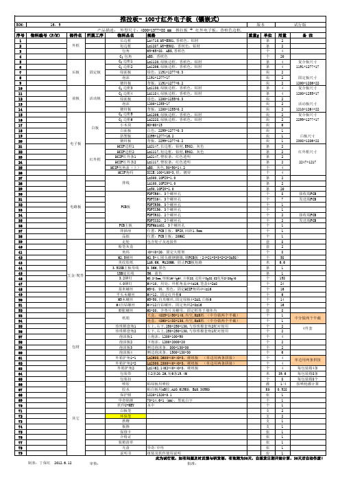
推拉板-BOM(85-100)
包材
其它
2012.6.12
条 2 条 2 个 4 个 20 条 4 复合板尺寸 条 4 1191*1277*17 块 2 块 2 固定板尺寸 块 2 1200*1286*22 条 4 复合板尺寸 条 4 1200*1255*17 块 2 块 2 活动板尺寸 块 2 1210*1264*22 块 2 复合板尺寸 块 2 2299*1277*17 块 6 块 1 块 1 白板尺寸 块 1 2308*1286*22 条 2 条 2 红外框尺寸 条 2 条 2 2247*1217 个 4 个 4 条 2 条 2 条 20 个 8 接收端PCB 个 7 发送端PCB 个 1 个 1 个 2 接收端PCB 个 2 发送端PCB 个 1 个 1 个 1 套 8 套 2 40*40*20,固定大框架 个 8 M2.5*4,圆头碳钢镀镍,锁PCB板(24+21+3+3+2+2+3=58) 个 58 L=6.6M, W=20MM,防止PCB板短路 米 6.6 0.36M,黑色 条 1 5M,蓝色 条 1 M3.2*8mm,绿板16*4=64,白板22,走轮4*8=32,C2包角2*20=40 个 158 M4*10, 用处:外框角盖4*4=16,笔盒4*2=8 个 24 M5*8,钢,黑色,固定HCIP角码4*4=16 个 16 M4*12,固定红外框6 个 6 M5*50,自攻螺丝,固定绿板4*2=8,白板6 个 14 M4*12自钻螺丝,固定角码2*8=16 个 16 M8*80,含垫片及螺母,固定框体于墙体内 套 8 天盒,4885*1450*140,内空,K=K纸 (中分做两个半截) 个 1 中分做两个半截 地盒,4860*1438*130,内空,K=K纸 (中分做两个半截) 个 1 左上,右下,250*250*130,与珍珠棉套角2配对使用 个 2 4件套 左下,右上,250*250*130,与珍珠棉套角1配对使用 个 2 上泡沫,1200*100*90 个 4 下泡沫,1200*2000*20 个 2 侧边泡沫条,800*130*30 个 2 侧边泡沫条,1500*130*30 个 6 L=2600,2600*40*40*3,硬纸板 (单边用两条拼接) 个 4 单边用两条拼接 L=2300,2300*40*40*3,硬纸板 (单边用两条拼接) 个 4 L=1462,1462*40*40*3,硬纸板 个 4 每包装箱4条 长2条20.2M,短6条19.4M 米 39.6 每包装箱8条 个 8 每包装箱8个 贴绿板用喷胶 灌 1/4 按喷枪灌计算 贴白板用AB胶,A=0.619KG,B=0.309KG KG 0.928 1820*1320*0.1 张 1 70*14.6*1 (mm),黑底白字 个 1 永中 个 1 支 2 支 2 支 1 支 1 张 1 张 1 张 1 华奇/中性 张 1 组装及软件使用说明 份 1 此为试行版,如有问题及时反馈与研发部,有效期为30天,自签发日期开始计算,30天后自动作废! 批准:
SAFE STEP 100 说明书

SAFE STEP ®100Part Code: Grey-43266, Tile Red-43267, Safety Yellow-43277 Pack Size: 5 LitresDescriptionSAFE STEP ® 100 is a single pack, epoxy ester anti-slip floor coating designed for application in areas of heavy pedestrian traffic. This high performance safety coating is easy to apply and offers optimum adhesion to metal, concrete and timber surfaces.SAFE STEP ® 100 has a shelf life of up to two years if stored in unopened containers. A partially used container may be resealed and retained for future use.SAFE STEP ® 100 resists petrol, oil, acids and aliphatic solvents.Technical Data (Typical)Colour:Tile Red, Grey and Safety Yellow Chemical Type: Single pack epoxy ester Density (Kg/L): BS3900A191.67 Pot Life:IndefiniteAverage Curing Times: the figures are given as a guide only. Factors such as air movement and humidity must also be consideredLight Traffic: Heavy Traffic:Full Chemical Resistance:12 hours @ 21°C 72 hours @ 21°C 7 days Theoretical Coverage Per Pack per coat: This figure makes no allowance for substrate profile, uneven application or losses in containers or rollers/brushes. Spray: Roller: Trowel:6.6 m 2 5.0 m 2 6.0 m 2Shelf Life: 2 years Flash Point:27°C Application Temperature: 10-30°C Storage Conditions:10-30°CEU limited valve for this product (CAT A/i):600g/l(2007) / 500g/l (2010)This product contains max. 385 g/l VOCVolume Solids: 61%Pendulum Slip Resistance (4S Slider – Product applied byroller) (BS7976)Pendulum Test Values (PTV) Parallel:Perpendicular: Slip potential classification Dry – 94 (Low slip potential)* Wet – 86 (Low slip potential)* Oily – 75 (Low slip potential)* Dry – 103 (Low slip potential)* Wet – 99 (Low slip potential)* Oily – 87 (Low slip potential)*Heat Resistance: -20 to 90°CChemical Resistance: Refer to separate Guide ‘Chemical Resistance Guide for ROCOL® SafeStep Anti-slip Coatings’*Potential to slip as interpreted in the guideline from UKSRG, 2011 recommended by the HSESlip potential classification, based on pendulumtest values (PTV)PTVHigh slip potential 0-24Moderate slip potential 25-35Low slip potential 36 +Surface PreparationApply SAFE STEP®100 to clean, dry surfaces only. Remove all paint, rust and mill scale preferably by grit-blasting. Remove oil, dirt, wax by dissolving in a suitable water washable cleaner/degreaser.All surfaces must be completely dry before application. Porous surfaces such as concrete and wood should be primed first using SAFE STEP®Non-Metal Primer to seal the surface. Metal surfaces should be primed with SAFE STEP®Metal Primer. New concrete should be allowed to cure for a minimum of 28 days before coating.Application1. SAFE STEP®100 is a single component, epoxy ester coating.2. Thoroughly mix contents preferably with a mechanical mixer such as a pneumatic drill motor with a jiffy-mixing blade until mixed materialassumes a uniform colour and appearance.3. SAFE STEP®100 can be applied at surface temperatures between 10o C and 40o C. Application is not recommended when surfacetemperature is above 40o C or below 10o C. At below 10o C curing time will increase substantially.4. SAFE STEP®100 can be applied by hard roller, trowel or spray equipment.Application TechniquesFor a tidy edge, mask off the area to be coated with masking tape. Remove masking tape whilst SAFE STEP®100 is still wet by pulling away from the area.Roller ApplicationRolled application provides the most aggressive non-slip characteristics with an irregular, ridged surface.1. Only use a hard, phenolic coated, roller supplied by ROCOL® Site Safety Systems for applying SAFE STEP®100.2. Pour a pool of the mixed product onto the prepared substrate.3. Roll material in one direction only, towards body in slow straight strokes using moderate pressure on the handle. Do not over-roll toomany times or press down too heavily.4. For maximum effect, rolling should be carried out perpendicular to the direction of traffic. Roll across ramps not down.Trowel ApplicationTrowelled applications provide excellent anti-slip characteristics with a rough textured finish.1. Use a flexible bladed plasterer’s finishing trowel approximately 10 x 30 cm. Wetting trowel with xylene will help improve surface finish.2. Pour a pool of SAFE STEP® 100 onto the prepared surface.3. Hold the trowel at 45 degrees angle to the surface. Pull material towards body with a sweeping motion reversing the angle on theopposite stroke.Spray ApplicationSprayed applications will result in a uniform appearance with good anti-slip characteristics and is an ideal method for large areas.There are two types of spray equipment recommended for spraying SAFE STEP®100. The choice depends on the size of the area to be coated.Hopper Gun (for small areas up to 50m2)Gun Type: Gravity fed hopper gun incorporating a 5mm nozzle, 5-litre hopper and elbow adapter for aiming at the floor.Air supply: 40-60psi air pressure. Ensure the air is oil free.Spray the product in a linear motion at a distance of 40cm from the surface with an overlap of approximately 30%.To clean equipment use xylene immediately after use.Pressure Pot Sprayer (for large areas over 50m2)Machine type: bottom outlet pressure pot nominally 30-50 litre capacity equipped with a double regulator and air driven agitator.Air supply: typically 50cubic feet per minute.Fluid pressure: typically 2-3 bar (30-45 psi)Fluid hose: 25mm diameter bore reinforced pvc pipeAtomising air pressure: typically 3-4 bar (45-60 psi)Tip diameter: 6mmFluid inlet to receive 25cm bore diameter PVC pipe. Air inlet to receive a 6mm-diameter airline.With the spray nozzle removed and atomising air isolated slowly build up the fluid pressure to allow product to flow along the fluid pipe and through the gun into a container. This is done to prime the pipelines and remove any air. Note the pressure reading when the product is just flowing easily (i.e. jet of material reaching 40-50cm from gun). Switch off the air supply. Replace the spray nozzle and then rebuild the fluidpressure to the noted reading. Once product is flowing out of the nozzle begin to increase the atomising air pressure at the gun. As this pressure is built up the flow of product will form a spray pattern.It is essential to match up the atomising air with the product fluid pressure, i.e. if the spray gun is not forming a spray pattern then there is not enough atomising air for the flow-rate. This can be remedied in one of two ways:1. Reduce fluid pressure.2. Increase atomising pressure.Once an even spray pattern is achieved spraying can commence in a linear manner with approximately 30% overlap on each pass.All components of the machine should be cleaned with xylene solvent immediately after use.Surface MaintenanceIt is essential that the SAFE STEP®100 coating is cleaned regularly to maximise anti-slip performance. The use of a water-based biodegradable detergent cleaner and a long handled fibre bristled brush or a suitable floor cleaning machine is recommended. After cleaning the surface should be rinsed thoroughly with clean water and allowed to dry.LimitationsHigher temperatures will shorten drying time and conversely, lower temperatures and high relative humidity will lengthen drying time. Exterior applications must be protected from rain for at least 12 - 24 hours after application according to humidity. Protect from heavy rain or extended exposure to water, oil and chemicals for 5 to 7 days. Although extremely durable, SAFE STEP® 100 is not a permanent coating and will require occasional touching up, especially in heavily trafficked areas.Health & SafetyRefer to Safety Data Sheet before use. If further copies are required or for further information, please contact ROCOL at the address below:Safety Data Sheets – Safety data sheets are available for download from our website or may be obtained from your usual ROCOL® contact.。
ASIA PP-M20 8010-M20 Datasheet
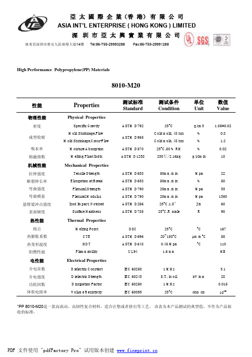
性能Properties测试标准Standard 测试条件Condition 单位Unit 数值Value物理性能Physical Properties密度Specific Gravity ASTM D79223°C g/cm3 1.05±0.02Mold Shrinkage,Flow Cold mold, 48 hrs %0.8Mold Shrinkage,Cross-Flow Cold mold, 48 hrs % 1.2吸水率Moisture Absorption ASTM D57023°C,50 % RH %0.02熔融指数Melting Float IndtxASTM D1238230℃/ 2.16kgg/10min10机械性能Mechanical Properties拉伸强度Tensile Strength ASTM D63850mm/min Mpa 22断裂伸长率Elongation at Break ASTM D63850mm/min %50弯曲强度Flexural Strength ASTM D79020mm/min Mpa 33弯曲模量Flexural Modulus ASTM D79020mm/min Mpa 1350悬臂梁冲击强度Izod Impact, Notched ASTM D25623°C,1/8〞J/m 60表面硬度Surface HardnessASTM D78523°C,R scaleR90热性能Thermal Properties熔点Melting PointDSC 23°C °C 167热膨胀系数CTE ASTM D69620~150°C µm/m °C 55热变形温度HDT ASTM D6480.45 Mpa °C110阻燃性能FlammabilityUL941.6 mmHB电性能Electrical Properties介电常数Dielectric Constant IEC 60250 1 MHz 3.1介电强度Dielectric Strength IEC 60243S/T, in oil kV/mm28功耗因数Dissipation Factor IEC 60250 1 MHz 0.015体积电阻率Volume ResistivityIEC 6009323°Cohm ·cm 1016High Performance Polypropylene(PP) Materials成型收缩*PP 8010-M20是一款高流动、高韧性复合材料,适合注塑或者挤出等工艺。
汉高脱脂剂讲义
PacZAC 1003
表面清洗
VR
Parco
P3
钢铁工业用汉高脱脂剂
PacZAC 1003
冷轧板表面的污染物
冷轧时使用的轧制油和乳化液 轧制过程中产生的
--金属颗粒 --分解的碳氢化合物 --附带的化学反应产物(如铁皂化物)
退火时产生的碳及分解的碳氢化合物 钢铁储运过程中使用的防锈油 机械油的泄漏等
COO-R
(硬脂酸酯)
CH3-CH2-CH2-CH2-CH2-CH2-CH2-CH2-CH2-CH2-CH2-CH2-CH2-CH2-CH2-CH2-CH2-+CORO-O-NHa
(硬脂酸钠皂)
(醇)
PacZAC 1003
无机组分/表面活性剂协同作用
100
80
60
40
20
0
01 3 5
10
处理时间 (min)
无机组分
无机组分浓度: 2,0 %
+ 表面活性剂 表面活性剂浓度: 0,1 %
温度: 60 °C
无机组分 表面活性剂
水
PacZAC 1003
温度和浓度的影响
[ mg C /m² ]
30
25
20
15
10
5
0
3%
4%
浓度
50°C 60°C 70°C
5%
pressure 2bar 2 min treatment time P3-percy 704
- 减少表面张力,使表面润湿 - 去除油污 - 有一定程度的消泡作用
PacZAC 1003
轧制油和脱脂剂中的成分
脱脂剂:
轧制油
碱 (NaOH, KOH)
锂离子-Materials for high-energy density batteries

Chapter14Materials for High-energy Density Batteries Arumugam ManthiramAbstract Lithium-ion batteries have emerged as the choice of rechargeable power source as they offer much higher energy density than other systems.However, their performance factors such as energy density,power density,and cycle life depend on the electrode materials employed.This chapter provides an overview of the cathode and anode materials systems for lithium-ion batteries.After pro-viding a brief introduction to the basic principles involved in lithium-ion cells, the structure-property-performance relationships of cathode materials like layered LiMO2(M=Mn,Co,and Ni)and their soiled solutions,spinel LiMn2O4,and olivine LiFePO4are presented.Then,a brief account of the carbon,alloy,oxide, and nanocomposite anode materials is presented.14.1IntroductionBatteries are the main energy storage devices used in modern society.They power invariably the portable devices we use in our daily life.They are also being pursued and developed intensively for widespread automobile applications.With respect to the topic of this book,batteries are also critical to store the energy harvested from various sources like solar,wind,thermal,strain,and inertia and to use the harvested energy efficiently when needed.In all of these applications,the energy density of the battery,which is the amount of energy stored per unit volume(W h/L)or per unit weight(W h/kg),is a critical parameter.The amount of energy stored depends on the capacity(amount of charge stored)per unit volume(A h/L)or per unit weight(A h/kg)and the voltage(V)each cell can deliver.In addition,rechargeability,charge–discharge cycle life,and the rate at which the cell can be charged and discharged are also important parameters.Moreover,cost and environmental impact considerations need to be taken into account.All of these parameters and properties are related to the battery chemistry and materials involved.A.Manthiram(B)Electrochemical Energy Laboratory,Materials Science and Engineering Program,The University of Texas at Austin,Austin,TX78712,USAe-mail:rmanth@365 S.Priya,D.J.Inman(eds.),Energy Harvesting Technologies,DOI10.1007/978-0-387-76464-114C Springer Science+Business Media,LLC2009366A.Manthiram50100150200250G r a v i m e t r i c E n e r g y D e n s i t y (W h /k g )Volumetric Energy Density (Wh/L)Fig.14.1Comparison of the gravimetric and volumetric energy densities of lithium–ion batteries with those of other rechargeable systemsAmong the various rechargeable battery chemistries known to date,lithium–ion batteries offer the highest energy density when compared with the other recharge-able battery systems such as lead–acid,nickel–cadmium,and nickel–metal hydride batteries as shown in Fig.14.1.The higher volumetric and gravimetric energy den-sities of the lithium–ion cells are due to the higher cell voltages (∼4V)achievable by the use of non-aqueous electrolytes in contrast to <2V achievable with most of the aqueous electrolyte-based cells.This chapter,after briefly providing the basic principles involved in lithium–ion cells,focuses on the various materials systems employed or being currently pursued to maximize the energy density,power den-sity,or both,while keeping in mind the other parameters like cycle life,cost,and environmental concerns.14.2Principles of Lithium–Ion BatteriesLithium–ion batteries involve a reversible insertion/extraction of lithium ions into/from a host matrix during the discharge/charge process as shown in Fig.14.2.The host matrix is called as a lithium insertion compound and serves as the elec-trode material in the cell.The present generation of lithium–ion cells mostly uses graphite and layered LiCoO 2as the lithium insertion compounds,which serve,respectively,as the anode and cathode materials.A lithium-containing salt such as LiPF 6dissolved in a mixture of aprotic solvents like ethylene carbonate (EC)and diethyl carbonate (DEC)is used as the electrolyte.During the charging process,the lithium ions are extracted from the layered LiCoO 2cathode,flow through the electrolyte,and get inserted into the layers of the graphite anode,while the electrons flow through the external circuit from the LiCoO 2cathode to the graphite anode in order to maintain charge balance.Thus,the charging process is accompanied by14Materials for High-energy Density Batteries367 Fig.14.2The charge/discharge process involved in a lithium–ion cell consisting of graphite as ananode and layered LiCoO2as a cathodean oxidation reaction(Co3+to Co4+)at the cathode and a reduction reaction at the anode.During discharge,exactly the reverse reactions occur at the anode and cathode with theflow of lithium ions(through the electrolyte)and electrons from the anode to the cathode.The free energy change involved in the relevant chemical reaction14.1is taken out as electrical energy during the discharge process:LiCoO2+C6→Li1−x CoO2+Li x C6(14.1)The open-circuit voltage V oc of such a lithium–ion cell shown in Fig.14.2is given by the difference in the lithium chemical potential between the cathode(μLi(c))and the anode(μLi(a))as follows:V oc=μLi(c)−μLi(a)F(14.2)where F is the Faraday constant.Figure14.3shows a schematic energy diagram of a cell at open circuit.The cell voltage V oc is determined by the energies involved in both the electron transfer and the Li+transfer.While the energy involved in electron transfer is related to the work functions of the cathode and the anode,the energy involved in Li+transfer is determined by the crystal structure and the coordination geometry of the site into/from which Li+ions are inserted/extracted(Aydinol and Ceder,1997).Although the cell voltage is a function of the separation between the redox energies of the cathode(E c)and anode(E a),thermodynamic stability consid-erations require the redox energies E c and E a to lie within the bandgap E g of the electrolyte,as shown in Fig.14.3,so that no unwanted reduction or oxidation of the electrolyte occurs during the charge–discharge process.Thus,the electrochemical stability requirement imposes a limitation on the cell voltage as follows:FV oc=μLi(c)−μLi(a)<E g(14.3)368A.ManthiramocElectrolyte/separator HOMOE E c E Fig.14.3Schematic energy diagram of a lithium cell at open circuit.HOMO and LUMO refer,respectively,to the highest occupied molecular orbital and lowest unoccupied molecular orbital in the electrolyteSeveral criteria should be satisfied in order for a lithium insertion compound to be successful as a cathode or an anode material in a rechargeable lithium cell.Some of the most important criteria are listed below.rThe cathode should have a low-lithium chemical potential (μLi(c))and the anode should have a high-lithium chemical potential (μLi(a))to maximize the cell volt-age (V ).This implies that the transition metal ion M n +in the lithium insertion compound Li x M y X z should have a high oxidation state to serve as a cathode and a low oxidation state to serve as an anode.rThe lithium insertion compound Li x M y X z should allow an insertion/extraction of a large amount of lithium per unit weight or per unit volume to maximize the cell capacity (A h/L or A h/kg).This depends on the number of lithium sites available in the lithium insertion/extraction host for reversible lithium inser-tion/extraction and the accessibility of multiple valences for M in the lithium insertion/extraction host.A combination of high capacity and cell voltage can maximize the energy density (W h/L or W h/kg),which is given by the product of the cell capacity and cell voltage.rThe lithium insertion compound Li x M y X z should support a reversible inser-tion/extraction of lithium with no or minimal changes in the host structure over the entire range of lithium insertion/extraction in order to provide good cycle life for the cell.This implies that the insertion compound Li x M y X z should have good structural stability without breaking any M–X bonds.r The lithium insertion compound should support both high-electronic conductiv-ity (σe )and high-lithium–ion conductivity (σLi )to facilitate fast charge/discharge (rate capability)and offer high-power capability,i.e.,it should support mixed ionic–electronic conduction.This depends on the crystal structure,arrangement of the MX n polyhedra,geometry,and interconnection of the lithium sites,nature,and electronic configuration of the M n +ion,and the relative positions of the M n +and X n −energies.14Materials for High-energy Density Batteries369 r The insertion compound should be chemically and thermally stable without undergoing any reaction with the electrolyte over the entire range of lithium insertion/extraction.r The redox energies of the cathode and anode in the entire range of lithium insertion/extraction process should lie within the bandgap of the electrolyte as shown in Fig.14.3to prevent any unwanted oxidation or reduction of theelectrolyte.r The lithium insertion compound should be inexpensive,environmentally benign, and lightweight from a commercial point of view.This implies that the M n+ion should preferably be from the3d transition series.In addition to the criteria outlined earlier for the cathode and the anode materials, the electrolyte should also satisfy several criteria.The electrolyte should have high lithium–ion conductivity,but should be an electronic insulator in order to avoid internal short-circuiting.A high-ionic conductivity in the electrolyte is essential to minimize IR drop or ohmic polarization and realize a fast charge–discharge process (high rate or power capability).With a given electrolyte,the IR drop due to elec-trolyte resistance can be reduced and the rate capability can be improved by having a higher electrode interfacial area and thin separators.The electrolyte should also have good chemical and thermal stabilities without undergoing any direct reaction with the electrodes.It should act only as a medium to transport efficiently the Li+ ions between the two electrodes(anode and cathode).Additionally,the engineer-ing involved in cell design and fabrication plays a critical role in the overall cell performance including electrochemical utilization,energy density,power density, and cycle life(Linden,1995).For example,although ideally high-electronic con-ductivity and lithium–ion diffusion rate in the electrodes are preferred to minimize cell polarizations,the electronic conductivity of the electrodes can be improved by adding electronically conducting additives such as carbon.However,the amount of additive should be minimized to avoid any undue sacrifice in cell capacity and energy density.Finally,cell safety,environmental factors,and raw materials and processing/manufacturing costs are also important considerations in materials selec-tion,cell design,and cell fabrication.14.3Cathode MaterialsIntensive materials research during the past three decades has led to the identi-fication and development of several lithium insertion compounds as cathodes for lithium–ion batteries(Whittingham and Jacobson,1982;Gabano,1983;Venkatasetty, 1984;Pistoia,1994;Julien and Nazri,1994;Wakihara and Yamamoto,1998;Nazri and Pistoia,2003).Although initial efforts were focused on transition metal chalco-genides(sulfides and selenides),their practical use was limited as it is difficult to achieve high-cell voltages with the chalcogenide cathodes.The cell voltage is limited to<2.5V versus metallic lithium anode with the chalcogenides due to an overlap of the higher valent M n+:d band with the top of the nonmetal:p band370 A.Manthiram and the inability to stabilize higher oxidation states of the transition metal ions in chalcogenides.For example,an overlap of the M n+:3d band with the top of the S2−:3p band results in an introduction of holes into the S2−:3p band to form S22−ions rather than oxidizing the transition metal ions and accessing higher valent M n+.Recognizing this difficulty with chalcogenides,Goodenough’s group at the University of Oxford focused on oxide cathodes during the1980s(Mizushima et al., 1980;Goodenough et al.,1980;Thackeray et al.,1983).The location of the top of the O2−:2p band much below the top of the S2−:3p band and a larger raising of the M n+:d energies in an oxide when compared with that in a sulfide due to a larger Madelung energy make the higher valent states accessible in oxides.For example, while Co3+can be readily stabilized in an oxide,it is difficult to stabilize Co3+in a sulfide since the Co2+/3+redox couple lies within the S2−:3p band.Accordingly,several transition metal oxide hosts crystallizing in different struc-tures have been identified as cathode materials during the past25years.Among them,oxides with a general formula LiMO2(M=Mn,Co,and Ni)having a layered structure,LiMn2O4having the spinel structure,and LiFePO4having the olivine structure have become appealing cathodes for lithium–ion batteries.These three systems of cathodes are discussed in the sections below.14.3.1Layered Oxide CathodesLiMO2with M=Co and Ni crystallize in a layered structure in which the Li+ and M3+ions occupy the alternate(111)planes of the rock salt structure so that the MO2sheets alternate with Li+layers along the c-axis as shown in Fig.14.4.The structure consists of a cubic close-packed oxygen array with the Li+ions occupying the octahedral interstitial sites and three MO2sheets per unit cell.Accordingly,this structure is designated as the O3layer structure in which the letter“O”refers to the presence of the alkali metal ions in the octahedral sites and the number“3”refers to the number of MO2sheets per unit cell.While the interconnected lithium–ion sites through the edge-shared LiO6octahedral arrangement between the stronglyMO2LiMO2LiMO2LiMO2Fig.14.4Crystal structure of layered LiMO2(M=Co or Ni)showing the arrangement of Li+ ions between the strongly bonded MO2sheets14Materials for High-energy Density Batteries 371bonded MO 2layers provide high lithium–ion conductivity σLi ,the edge-shared MO 6octahedral arrangement with a direct M–M interaction provides good electronic conductivity σe ,which are critical to realize fast charge–discharge rates.A large charge and ionic radii differences between the Li +and Co 3+ions offer a good ordering without any mixing between the cations in the lithium and transition metallayers.Also,a strong preference of the low spin Co 3+:3d 6(t 62g e 0g )ions for theoctahedral sites prevents the migration of the Co 3+ions from the transition metal layer to the lithium layer via the neighboring tetrahedral sites during the charge–discharge process unlike in the case of other layered oxides like LiMnO 2.On the other hand,the highly oxidized Co 3+/4+redox couple with a large work function offers a high-discharge voltage of around 4V versus Li /Li +(Mizushima et al.,1980).Moreover,with a direct Co–Co interaction and a partially filled t 2g orbital forCo 4+(t 52g e 0g )ions,Li 1−x CoO 2becomes a metallic conductor on partially charging it.As a result LiCoO 2has become an attractive cathode,and most of the lithium–ion cells presently use LiCoO 2as the cathode.However,only 50%of the theoretical capacity of LiCoO 2,which corresponds to a reversible extraction of 0.5lithium ions per LiCoO 2formula and around 140A h/kg,could be utilized in practical cells.Although early studies attributed this limi-tation in practical capacity to an ordering of lithium ions and consequent structural distortions (hexagonal to monoclinic transformation)around x =0.5in Li 1−x CoO 2(Reimers and Dahn,1992),more recent characterizations of chemically delithi-ated samples suggest that the limitation is primarily due to the chemical insta-bility at deep charge for (1−x )<0.5in Li 1−x CoO 2(Venkatraman et al.,2003;Choi et al.,2006).This is supported by the fact that the reversible capacity of LiCoO 2has been increased significantly close to 200A h/kg with a reversible extrac-tion of 0.7lithium ions per formula unit on modifying the surface of LiCoO 2by other oxides like Al 2O 3,ZrO 2,and TiO 2(Cho et al.,2001a,b).The surface modifi-cation prevents the direct contact of the highly oxidized Co 3+/4+with the electrolyte and thereby improves the chemical stability.The chemical instability of Li 1−x CoO 2at deep charge also leads to safety concerns.The chemical instability of Li 1−x CoO 2is due to a significant overlap of the redox active Co 3+/4+:t 2g band with the top of the O 2−:2p band as shown in Fig.14.5and the consequent introduction of significant amount of holes into the O 2−:2p band at deep charge (i.e.(1−x )<0.5).Although the analogous layered Li 1−x MnO 2and Li 1−x NiO 2offer better chemical stability than Li 1−x CoO 2as the redox active Mn 3+/4+:e g and Ni 3+/4+:e g bands lie well above the O 2−:2p band or barely touches the top of O 2−:2p band (Fig.14.5),Li 1−x MnO 2suffers from a migration of the Mn 3+ions from the transition metal plane to the lithium plane to form a spinel-like phase while Li 1−x NiO 2suffers from phase changes during the charge–discharge process.As a result,both LiMnO 2and LiNiO 2are not promising cathodes.Although both LiMnO 2and LiNiO 2by themselves could not be used as cath-odes,solid solutions among LiMnO 2,LiCoO 2,and LiNiO 2have become attractive cathodes.For example,layered LiNi 1/3Mn 1/3Co 1/3O 2has emerged as a replace-ment for LiCoO 2as it offers a lower cost and better safety when compared with372A.ManthiramLiNiO 2O 2–: 2p Ni 3+/4+: e g Ni 3+/4+: t 2gLiMnO 2O 2–: 2pMn 3+/4+: e g Mn 3+/4+–: t2g LiCoO 2Co 3+/4+: t 2gO 2–: 2p Co 3+/4+: egFig.14.5Comparison of the energy diagrams of LiCoO 2,LiNiO 2,and LiMnO 2LiCoO 2.While the lower cost arises from a lower raw material cost of Mn and Ni when compared with that of Co,the better safety is due to the lying of the Mn 3+/4+:e g and Ni 3+/4+:e g bands above the O 2−:2p band when compared with the Co 3+/4+:t 2g band as seen in Fig.14.5.The better chemical stability also allows Li 1−x Ni 1/3Mn 1/3Co 1/3O 2to be charged to higher cutoff charge voltages with a higher reversible capacity of around 180A h/kg when compared with Li 1−x CoO 2(Choi and Manthiram,2004).More recently,solid solutions between layered Li[Li 1/3Mn 2/3]O 2,which is com-monly designated as Li 2MnO 3,and layered Li[Ni 1−y −z Mn y Co z ]O 2have also become interesting as they exhibit much higher capacities of around 250A h/kg,which is nearly two times higher than that found with LiCoO 2(Lu et al.,2002;Armstrong et al.,2006;Thackeray et al.,2007;Arunkumar et al.,2007a,b).These layered solid solutions between Li[Li 1/3Mn 2/3]O 2and Li[Ni 1−y −z Mn y Co z ]O 2exhibit an initial sloping region A,which corresponds to the oxidation of the transition metal ions to 4+state,followed by a plateau region B,which corresponds to an oxidation of the O 2−ions and an irreversible loss of oxygen from the lattice,during the first charge as seen in Fig.14.6.After the first charge,the material cycles with a sloping discharge–charge profile involving a reversible reduction–oxidation of the transition metal ions.010020030012345V o l t a g e (V )Capacity (mAh/g)B A Fig.14.6First charge–discharge profiles of solid solutions between layered Li[Li 1/3Mn 2/3]O 2and Li[Ni 1−y −z Mn y Co z ]O 214Materials for High-energy Density Batteries 37305010015020025030035023452345234523452345V o l t a g e (V )Specific capacity (mAh/g)x = 0.3Unmodified Al 2O 3 modified x = 0.5x = 0.4x = 0.6x = 0.7Fig.14.7First charge–discharge profiles of the layered (1−x )Li[Li 1/3Mn 2/3]O 2−x Li[Ni 1/3Mn 1/3Co 1/3]O 2solid solutions before and after surface modification with Al 2O 3followed by heating at 400◦CHowever,these layered solid solution cathodes tend to exhibit a large irreversible capacity loss in the first cycle,i.e.,a large difference between the first charge capac-ity and the first discharge capacity as seen in Fig.14.6.This large irreversible capac-ity loss is generally believed to be due to the extraction of lithium as “Li 2O”in the plateau region B in Fig.14.6and an elimination of the oxide ion vacancies formed to give an ideal composition “MO 2”without any oxide ion vacancies existing in the lattice at the end of first charge,resulting in a less number of lithium sites avail-able for lithium insertion/extraction during the subsequent discharge–charge cycles (Armstrong et al.,2006;Thackeray et al.,2007).However,a careful analysis of the first charge and discharge capacity values recently with a number of compositions suggests that part of the oxide ion vacancies should be retained in the layered lattice to account for the high-discharge capacity values observed in the first discharge (Wu et al.,2008).The irreversible capacity loss observed during the first cycle could also be reduced by a modification of the cathode surface with other oxides like Al 2O 3(Wu et al.,2008;Park et al.,2001).For example,Fig.14.7shows the first charge–discharge profiles of a series of solid solutions between layered Li[Li 1/3Mn 2/3]O 2and Li[Ni 1/3Mn 1/3Co 1/3]O 2before and after surface modification with Al 2O 3,while374 A.Manthiram200250300D i s c h a r g e C a p a c i t y (m A h /g )Cycle number 200250300200250300200250300200250300Fig.14.8Cyclability of the layered (1−x )Li[Li 1/3Mn 2/3]O 2−x Li[Ni 1/3Mn 1/3Co 1/3]O 2solid solutions before and after surface modification with Al 2O 3followed by heating at 400◦CFig.14.8shows the corresponding cyclability data.Clearly,the surface modified samples exhibit lower irreversible capacity loss and higher dis-charge capacity values than the pristine,unmodified samples.This improvement in the surface modified samples has been explained on the basis of the retention of more number of oxide ion vacancies in the layered lattice after the first charge when compared with that in the unmodified samples.It is remarkable that the surface modified (1−x )Li[Li 1/3Mn 2/3]O 2−x Li[Ni 1/3Mn 1/3Co 1/3]O 2composition with x =0.4exhibit a high-discharge capacity of 280mA h/g,which is two times higher than that of LiCoO 2.These oxides have high potential to increase the energy density values significantly.However,these layered oxides require charging up to about4.8V and more stable,compatible electrolyte compositions need to be developed.Moreover,oxygen is lost irreversibly from the lattice during the first charge,and it may have to be vented appropriately during cell manufacturing before sealing the cells.Furthermore,the long-term cyclability of these cathodes under more aggres-sive environments such as elevated temperatures need to be fully assessed.14.3.2Spinel Oxide CathodesLiMn 2O 4crystallizes in the normal spinel structure in which the Li +and the Mn 3+/4+ions occupy,respectively,the 8a tetrahedral and 16d octahedral sites ofthe cubic close-packed oxygen array(Fig.14.9)to give(Li)8a[M2]16d O4.While the interconnection of the8a tetrahedral sites via the neighboring empty16c octahedral sites offers a fast3D lithium–ion diffusion(highσLi)within the covalently bonded [Mn2]O4framework,the edge shared MnO6octahedra with a direct Mn–Mn interac-tion provide good electronic conductivityσe needed for high rate capability.Unlike the layered LiMO2cathodes that could suffer from the migration of the transition metal ions from the transition metal layer to the lithium layer,the3D[Mn2]O4 spinel framework provides excellent structural stability,supporting high rate capa-bility.Additionally,the lying of the Mn3+/4+:e g band well above the O2−:2p band as seen in Fig.14.5offers excellent chemical stability unlike the Co3+/4+couple. Moreover,Mn is inexpensive and environmentally benign.As a result,LiMn2O4 with a discharge voltage of about4V(Thackeray et al.,1983)has become appeal-ing as a cathode,particularly for high-power applications such as hybrid electric vehicles(HEV).However,only about0.8lithium ions per LiMn2O4formula unit could be reversibly extracted,which limit the practical capacity to<120A h/kg.Although an additional lithium could be inserted into the empty16c sites of(Li)8a[M2]16d O4 around3V versus Li/Li+to give the lithiated spinel{Li2}16c[M2]16d O4,it is accom-panied by a transformation of the cubic(Li)8a[M2]16d O4into tetragonal{Li2}16c[M2]16d O4due to the Jahn–Teller distortion associated with the high spin Mn3+:3d4(t32g e1g)ion.This results in poor capacity retention during cycling in the3Vregion due to huge volume changes,so the3V region cannot be utilized in practical cells.In addition to the lower capacity(<120A h/kg)when compared with that of the layered oxides,the LiMn2O4spinel cathode encounters severe capacity fade even in the4V region particularly at elevated temperatures.This has been attributedFig.14.9Crystal structure of LiMn2O4spinel with LiO4tetrahedra and edge-shared MnO6 octahedrato a disproportionation of Mn 3+ions into Mn 4+and Mn 2+ions in the presence of trace amounts of hydrofluoric acid generated by a reaction of the LiPF 6salt with the parts per million levels of water present in the electrolyte solution;while the Mn 4+ion remains in the solid,Mn 2+leaches out into the electrolyte and poisons the anode,resulting in capacity fade.Several efforts including cationic and anionic substitutions and surface mod-ifications (Park et al.,2001;Kannan and Manthiram,2002)have been pursued to overcome the capacity fade problem.Among them,optimized substitutions like Li[Mn 1.8Ni 0.1Li 0.1]O 4suppresses Mn dissolution drastically and improves the capacity retention significantly as seen in Fig.14.10(Shin and Manthiram,2003;Choi and Manthiram,2006,2007).However,such substitutions increase the man-ganese valence and decrease the capacity to around 80A h/kg.Nevertheless,the capacity values could be increased to around 100A h/kg without increasing the manganese dissolution by a partial substitution of fluorine for oxygen.For example,oxyfluoride compositions like Li[Mn 1.8Ni 0.1Li 0.1]O 3.8F 0.2exhibit excellent capacity retention at ambient and elevated temperatures (Fig.14.10)along with the high-rate capability (Choi and Manthiram,2006,2007).Although the capacity values708090100110120C a p a c i t y (m A h /g )010********6080100120Cycle NumberFig.14.10Comparison of the capacity retention of LiMn 2O 4(solid circles ),Li[Mn 1.8Ni 0.1Li 0.1]O 4(solid triangles ),and Li[Mn 1.8Ni 0.1Li 0.1]O 3.8F 0.2(open squares )spinel cathodes at 25and 60◦Cof the spinel cathodes are lower when compared with that of the layered oxides discussed in the previous section,the low cost of Mn and the high charge–discharge rate capabilities make the optimized oxyfluoride spinel cathodes appealing for high-power applications such as power tools and hybrid electric vehicles.Interestingly, the capacity values of the spinel cathodes could also be increased by blending with appropriate amounts of a layered oxide like LiNi1/3Mn1/3Co1/3O2without sacrific-ing the cost and rate capability benefits.One interesting way to increase the energy density of LiMn2O4spinel is to increase the operating voltage.For example,substitution of other transition metal ions like Ni2+for Mn3+/4+to give LiMn1.5Ni0.5O4has been found to increase the operating voltage to4.7V with a capacity of about130A h/kg(Zhong et al., 1997).In LiMn1.5Ni0.5O4,Mn is present as Mn4+and Ni is present as Ni2+,and the oxidation of Ni2+to Ni3+and Ni4+during the charging process and the oper-ation of the Ni2+/3+and Ni3+/4+couples along with an extraction/insertion of lithium from/into the tetrahedral sites offers a voltage of4.7V when compared with4V for the Mn3+/4+couple.It is interesting to note that while the Ni3+/4+ couple with an octahedral site lithium operates around4V in the layered oxides like LiNiO2,the same couple with a tetrahedral site lithium operates around4.7V in the spinel LiMn1.5Ni0.5O4.This is a direct reflection of the contributions of the energies involved in both the electron transfer(work function)and the Li+ion transfer(site energy)to the cell voltage as discussed in Section14.2.Although the synthesis of LiMn1.5Ni0.5O4encounters the formation of a small amount of NiO impurity,appro-priate cationic substitutions to give compositions like LiMn1.42Ni0.42Co0.16O4and LiMn1.5Ni0.42Zn0.08O4eliminate the impurity phase with a significant improvement in capacity retention(Arunkumar and Manthiram,2005).However,the major issue with this class of spinel cathodes is the electrolyte stability at4.7V.Development of more stable,compatible electrolytes could make these cathodes attractive for high power applications with a significantly increased energy density when compared with the LiMn2O4cathode.14.3.3Olivine Oxide CathodesOne disadvantage with layered oxide cathodes containing highly oxidized redox couples like Co3+/4+and Ni3+/4+is the chemical instability at deep charge and the associated safety problems.Recognizing this,oxides like Fe2(XO4)3that con-tain the polyanion(XO4)2−(X=S,Mo,and W)were initiated as lithium inser-tion/extraction hosts in the late1980s.Although the lower valent Fe2+/3+couple in a simple oxide like LiFeO2would be expected to offer a lower discharge voltage of<3V,the covalently bonded groups like(SO4)2−lower the redox energies of Fe2+/3+through inductive effect and increase the cell voltage to>3V(Manthiram and Goodenough,1987,1989).Following this,LiFePO4crystallizing in the olivine structure(Fig.14.11)and offering aflat discharge profile around3.4V with a theo-retical capacity of around170A h/kg was identified as a cathode(Padhi et al.,1997) in late1990s.Despite a higher capacity,the lower discharge voltage when compared。
PX804D非毒性通用防火胶封缴胶说明书

PX804D/BK/050PX804D/BK/100PX804D/BK/1000PX804D/BK/500PX804DA non-toxic general purpose flame retardant potting and encapsulating compound ApplicationKey Properties∙ PCB potting and encapsulation ∙ Capacitors ∙ Transformers∙ Deep sea electronics∙ High electrical insulating characteristics ∙ Non-toxic∙ Low shrinkage∙ Good thermal conductivity ∙ High adhesion∙Good chemical and water resistanceDescription● Basic Two-component epoxy system ● Resin RX804D ●HardenerHX804DPhysical Data (approx. – values) Resin Hardener Mixed Colour Black Amber Black Specific Gravity 1.8 1.00 1.7 Viscosity (mPas) @ 25°C 60000 500 9000Cure Schedule (150ml sample)TemperatureWorking Life (minutes) Gel Time (minutes) Light Handling (hours) Full Cure(hours)RT 90 360 24 48 60°C - - 2 480°C - - 1 2*RT is defined as 20-25°CThe above are typical values and will vary depending on the cured mass and application. Hotter temperatures may be used for faster cure but will result in higher post cure shrinkage and higher cure exotherm. Experimentation and testing is suggested to avoid side effects. For maximum properties a post cure may be required – Contact our technical service department for advice.Mix ratio by weight 8.6:1 Mix ratio by volume4.8:1Test Result Unit Peak exotherm (150g @ 25°C) 40 °C Shrinkage (volume) 0.3 % Thermal conductivity 0.85 W/m K Operating temperature range -55 to +130 °C (application & geometry dependent) Electric strength 18 kV/mm Volume Resistivity 1110 ohm.cm Hardness 80 Shore D Flammability Approvable to UL94-V0 Tensile strength 50 MPa Compressive strength 60 MPa Deflection Temperature 50 °C Co-efficient of expansion 35-55 ppm/°C Loss Tangent 0.060 50Hz Permittivity 4.8 50 Hz Continuous tracking index (Method IEC 60112) >850 V Water absorption (30 days @ 20°C) 0.3 % Elongation at break 2-5%Processing Typical PropertiesRoHS compliant YesUL94-V0 NoREACH (SVHC concentration) 0%PX804D is available in Bulk, Twinpacks, kits and sets*******************************************************************.ukNot availablePX804D/BK/025 PX804D/RD/1000PX804D/BK/050PX804D/BK/100PX804D/BK/250PX804D/BK/500PX804D/BK/750PX804D/BK/1000Twinpacks are pre-weighed resin and hardener components contained in a tough flexible film, separated by a removable clipand rail.Once the clip and rail is removed the resin and hardener is thoroughly mixed within the bag and is immediately ready for use.Mixing will normally take ~ 2 minutes due to the viscosity; but pay special attention to the corners.Twinpacks are ideal for small to medium production runs, prototyping and on-site or field use.The twinpack weight/volume may also be tailored to a specific size on request.For further details please visit RX804D/BK/4.5KG HX804D/NC/525GRX804D/BK/5KG HX804D/NC/5KGRX804D/BK/25KG HX804D/NC/10KGHX804D/NC/25KG Both resin and hardener are supplied in 5kg, 25kg and 200ltr drums and fully evacuated and ready for use.Care should be taken to ensure when mixing the resins air is not entrained in the mixture.If this is unavoidable the mixed resin and hardener should be re-evacuated before dispensing.The bulk resin and hardener materials can be dispensed from suitable dispensing machinery and Robnor Resins produce arange of these machines, details that can be provided on request.PX804D/BK/1KGKITPX804D/BK/25KGKITKits and Sets are provided in separate containers to the correct ratio.In Kit form, pour the hardener into the larger resin container and use it as a mixing vessel.Stir well using an appropriate mixer until homogeneous.Note: Incomplete mixing will be characterised by erratic or partially incomplete cure even after extended time periods.All equipment contaminated with mixed material should be cleaned before the material has hardened.TS130 is a suitable non-flammable cleaning agent, although other solvents may be found suitable.TS130 will also remove cured material provided it is allowed to soak for a number of hours.Material stored in the original unopened containers under cool dry condition between 15° and 25°C will have a shelf life of atleast 12 months.Once used the containers must be kept sealed to prevent effects from water, air or contaminants.Epoxy resin systems may cause sensitisation by skin contact or inhalation may be corrosive, harmful or toxic.It is therefore strongly recommended that skin and eye contact is avoided by the using of appropriate personal protective equipment such as gloves, safety glasses or goggles and overalls.Wash any contamination from the skin immediately and thoroughly and do not eat, smoke or drink in the working vicinity. Under normal working conditions a good source of ventilation is adequate, however if the material is heated, or where vapour levels are likely to exceed the occupational exposure limits appropriate respiratory protection must be worn.Local exhaust ventilation (LEV) may be required especially for curing ovens or where large volumes of material are curing. The above is given as a guide only; please refer to RX/HX804D Health and Safety data or our Technical Service Department for individual/specific advice.The results and information above does not constitute a specification and is given in good faith and without warranty.The information is derived from test/or extrapolations believed to be reliable and is quoted for guidance only.The product is offered for evaluation on the understanding the customer satisfies himself that the product is suitable for his intended by proper evaluation and testing.Robnor Resins LimitedHunts RiseSouth Marston ParkSwindon SN3 4TEUnited KingdomTel: +44 (0) 1793 823741Fax: +44 (0) 1793 827033Email:*****************.ukWeb: Buy Online: (UK only)PX804D/BK/050PX804D/BK/100PX804D/BK/1000PX804D/BK/500。
矿用防爆QBZ-80、120、200型1140(660V)开关原理教材 ppt课件
无法停 止
1、中 间继电 器卡死 或熔焊
1、 排除故 障或更 换继电 器
阻 容保护 器 电 阻烧毁
1、电 源三相 严重不 平衡 2、电 容击穿 3、电 容容量 电阻阻 值降低
1、 调 整 负 荷 , 使 三 相 尽 量 平 衡 2、 更 换 被 击 穿 电 容 3、 更 换 电 容 式 电 阻
原因1修触点或更换接钮2检查hk是否合上rd是否烧断或接触不好kl绕组是否烧断3更换损坏的二极管4更换线圈或接触器5找出并排除负载漏电处6排除故障或更换继电器处理方法起动后无法维持无法停止阻容保护器电阻烧毁三相严重不同步过载时保护器不动作rd熔断1电源电压低于75额定电压2反力弹簧调节过紧3辅助触点接触不良1换大截面电缆减少线路压降2放松反力弹簧但要保持一定的分闸速度3调整辅助触点使其接触良好1kl高压线圈短路或引线短路1保护器整定电流太大2保护器动作不可靠1接触器动导杆锁紧螺母松动2三相触头磨损程度不同1电源三相严重不平衡2电容击穿3电容容量电阻阻值降低1中间继电器卡死或熔焊1查出短路处排除故障更换rd1按电机容量的额定电流值调整保护器的合适整定电流2更换保护器1按说明书调整三相触头开距并拧紧锁螺母2调整或更换1调整负荷使三相尽量平衡2更换被击穿电容3更换电容式电阻1排除故障或更换继电器
ppt课件
4
技术数据
1 起动器的主要技术参数如表1所示:
起动器型号
Q B Z - 80
Q BZ- 12 0
QBZ-200
额 定电压 (V) 1140、660、380 1 140、66 0、380 1140、660、380
额 定电流 (A)
80
12 0
8002301FA中文资料
Copyright © 1988, Texas Instruments Incorporated PRODUCTION DATA information is current as of publication date.PACKAGING INFORMATIONOrderable Device Status(1)PackageType PackageDrawingPins PackageQtyEco Plan(2)Lead/Ball Finish MSL Peak Temp(3)5962-7603701VEA ACTIVE CDIP J161TBD Call TI Level-NC-NC-NC 5962-7603701VFA ACTIVE CFP W161TBD Call TI Level-NC-NC-NC 5962-7603701VFA ACTIVE CFP W161TBD Call TI Level-NC-NC-NC 7603701EA ACTIVE CDIP J161TBD Call TI Level-NC-NC-NC 7603701EA ACTIVE CDIP J161TBD Call TI Level-NC-NC-NC 7603701FA ACTIVE CFP W161TBD Call TI Level-NC-NC-NC 7603701FA ACTIVE CFP W161TBD Call TI Level-NC-NC-NC 76038012A ACTIVE LCCC FK201TBD Call TI Level-NC-NC-NC 76038012A ACTIVE LCCC FK201TBD Call TI Level-NC-NC-NC 7603801EA ACTIVE CDIP J161TBD Call TI Level-NC-NC-NC 7603801EA ACTIVE CDIP J161TBD Call TI Level-NC-NC-NC 7603801FA ACTIVE CFP W161TBD Call TI Level-NC-NC-NC 7603801FA ACTIVE CFP W161TBD Call TI Level-NC-NC-NC 8002301EA ACTIVE CDIP J161TBD Call TI Level-NC-NC-NC 8002301EA ACTIVE CDIP J161TBD Call TI Level-NC-NC-NC 8002301FA ACTIVE CFP W161TBD Call TI Level-NC-NC-NC 8002301FA ACTIVE CFP W161TBD Call TI Level-NC-NC-NCJM38510/07906BEA ACTIVE CDIP J161TBD Call TI Level-NC-NC-NCJM38510/07906BEA ACTIVE CDIP J161TBD Call TI Level-NC-NC-NCJM38510/07906BFA ACTIVE CFP W161TBD Call TI Level-NC-NC-NCJM38510/07906BFA ACTIVE CFP W161TBD Call TI Level-NC-NC-NCJM38510/30906B2A ACTIVE LCCC FK201TBD Call TI Level-NC-NC-NCJM38510/30906B2A ACTIVE LCCC FK201TBD Call TI Level-NC-NC-NCJM38510/30906BEA ACTIVE CDIP J161TBD Call TI Level-NC-NC-NCJM38510/30906BEA ACTIVE CDIP J161TBD Call TI Level-NC-NC-NCJM38510/30906BFA ACTIVE CFP W161TBD Call TI Level-NC-NC-NCJM38510/30906BFA ACTIVE CFP W161TBD Call TI Level-NC-NC-NC SN54LS257BJ ACTIVE CDIP J161TBD Call TI Level-NC-NC-NC SN54LS257BJ ACTIVE CDIP J161TBD Call TI Level-NC-NC-NC SN54LS258BJ ACTIVE CDIP J161TBD Call TI Level-NC-NC-NC SN54LS258BJ ACTIVE CDIP J161TBD Call TI Level-NC-NC-NC SN54S257J ACTIVE CDIP J161TBD Call TI Level-NC-NC-NC SN54S257J ACTIVE CDIP J161TBD Call TI Level-NC-NC-NC SN54S258J ACTIVE CDIP J161TBD Call TI Level-NC-NC-NC SN54S258J ACTIVE CDIP J161TBD Call TI Level-NC-NC-NC SN74LS257BD ACTIVE SOIC D1640Green(RoHS&no Sb/Br)CU NIPDAU Level-1-260C-UNLIMSN74LS257BD ACTIVE SOIC D1640Green(RoHS&no Sb/Br)CU NIPDAU Level-1-260C-UNLIMSN74LS257BDE4ACTIVE SOIC D1640Green(RoHS&no Sb/Br)CU NIPDAU Level-1-260C-UNLIMSN74LS257BDE4ACTIVE SOIC D1640Green(RoHS&no Sb/Br)CU NIPDAU Level-1-260C-UNLIMOrderable Device Status(1)PackageType PackageDrawingPins PackageQtyEco Plan(2)Lead/Ball Finish MSL Peak Temp(3)SN74LS257BDR ACTIVE SOIC D162500Green(RoHS&no Sb/Br)CU NIPDAU Level-1-260C-UNLIMSN74LS257BDR ACTIVE SOIC D162500Green(RoHS&no Sb/Br)CU NIPDAU Level-1-260C-UNLIMSN74LS257BDRE4ACTIVE SOIC D162500Green(RoHS&no Sb/Br)CU NIPDAU Level-1-260C-UNLIMSN74LS257BDRE4ACTIVE SOIC D162500Green(RoHS&no Sb/Br)CU NIPDAU Level-1-260C-UNLIMSN74LS257BN ACTIVE PDIP N1625Pb-Free(RoHS)CU NIPDAU Level-NC-NC-NCSN74LS257BN ACTIVE PDIP N1625Pb-Free(RoHS)CU NIPDAU Level-NC-NC-NC SN74LS257BN3OBSOLETE PDIP N16TBD Call TI Call TISN74LS257BN3OBSOLETE PDIP N16TBD Call TI Call TISN74LS257BNE4ACTIVE PDIP N1625Pb-Free(RoHS)CU NIPDAU Level-NC-NC-NCSN74LS257BNE4ACTIVE PDIP N1625Pb-Free(RoHS)CU NIPDAU Level-NC-NC-NCSN74LS257BNSR ACTIVE SO NS162000Green(RoHS&no Sb/Br)CU NIPDAU Level-1-260C-UNLIMSN74LS257BNSR ACTIVE SO NS162000Green(RoHS&no Sb/Br)CU NIPDAU Level-1-260C-UNLIMSN74LS257BNSRE4ACTIVE SO NS162000Green(RoHS&no Sb/Br)CU NIPDAU Level-1-260C-UNLIMSN74LS257BNSRE4ACTIVE SO NS162000Green(RoHS&no Sb/Br)CU NIPDAU Level-1-260C-UNLIMSN74LS258BD ACTIVE SOIC D1640Green(RoHS&no Sb/Br)CU NIPDAU Level-1-260C-UNLIMSN74LS258BD ACTIVE SOIC D1640Green(RoHS&no Sb/Br)CU NIPDAU Level-1-260C-UNLIMSN74LS258BDE4ACTIVE SOIC D1640Green(RoHS&no Sb/Br)CU NIPDAU Level-1-260C-UNLIMSN74LS258BDE4ACTIVE SOIC D1640Green(RoHS&no Sb/Br)CU NIPDAU Level-1-260C-UNLIMSN74LS258BDR ACTIVE SOIC D162500Green(RoHS&no Sb/Br)CU NIPDAU Level-1-260C-UNLIMSN74LS258BDR ACTIVE SOIC D162500Green(RoHS&no Sb/Br)CU NIPDAU Level-1-260C-UNLIMSN74LS258BDRE4ACTIVE SOIC D162500Green(RoHS&no Sb/Br)CU NIPDAU Level-1-260C-UNLIMSN74LS258BDRE4ACTIVE SOIC D162500Green(RoHS&no Sb/Br)CU NIPDAU Level-1-260C-UNLIMSN74LS258BN ACTIVE PDIP N1625Pb-Free(RoHS)CU NIPDAU Level-NC-NC-NCSN74LS258BN ACTIVE PDIP N1625Pb-Free(RoHS)CU NIPDAU Level-NC-NC-NCSN74LS258BN3OBSOLETE PDIP N16TBD Call TI Call TISN74LS258BN3OBSOLETE PDIP N16TBD Call TI Call TISN74LS258BNE4ACTIVE PDIP N1625Pb-Free(RoHS)CU NIPDAU Level-NC-NC-NCSN74LS258BNE4ACTIVE PDIP N1625Pb-Free CU NIPDAU Level-NC-NC-NCOrderable Device Status(1)PackageType PackageDrawingPins PackageQtyEco Plan(2)Lead/Ball Finish MSL Peak Temp(3)(RoHS)SN74LS258BNSR ACTIVE SO NS162000Green(RoHS&no Sb/Br)CU NIPDAU Level-1-260C-UNLIMSN74LS258BNSR ACTIVE SO NS162000Green(RoHS&no Sb/Br)CU NIPDAU Level-1-260C-UNLIMSN74LS258BNSRE4ACTIVE SO NS162000Green(RoHS&no Sb/Br)CU NIPDAU Level-1-260C-UNLIMSN74LS258BNSRE4ACTIVE SO NS162000Green(RoHS&no Sb/Br)CU NIPDAU Level-1-260C-UNLIMSN74S257D ACTIVE SOIC D1640Green(RoHS&no Sb/Br)CU NIPDAU Level-1-260C-UNLIMSN74S257D ACTIVE SOIC D1640Green(RoHS&no Sb/Br)CU NIPDAU Level-1-260C-UNLIMSN74S257DE4ACTIVE SOIC D1640Green(RoHS&no Sb/Br)CU NIPDAU Level-1-260C-UNLIMSN74S257DE4ACTIVE SOIC D1640Green(RoHS&no Sb/Br)CU NIPDAU Level-1-260C-UNLIMSN74S257N ACTIVE PDIP N1625Pb-Free(RoHS)CU NIPDAU Level-NC-NC-NCSN74S257N ACTIVE PDIP N1625Pb-Free(RoHS)CU NIPDAU Level-NC-NC-NC SN74S257N3OBSOLETE PDIP N16TBD Call TI Call TISN74S257N3OBSOLETE PDIP N16TBD Call TI Call TISN74S257NE4ACTIVE PDIP N1625Pb-Free(RoHS)CU NIPDAU Level-NC-NC-NCSN74S257NE4ACTIVE PDIP N1625Pb-Free(RoHS)CU NIPDAU Level-NC-NC-NC SN74S258DR OBSOLETE SOIC D16TBD Call TI Call TISN74S258DR OBSOLETE SOIC D16TBD Call TI Call TISN74S258N OBSOLETE PDIP N16TBD Call TI Call TISN74S258N OBSOLETE PDIP N16TBD Call TI Call TISN74S258N3OBSOLETE PDIP N16TBD Call TI Call TISN74S258N3OBSOLETE PDIP N16TBD Call TI Call TISNJ54LS257BFK ACTIVE LCCC FK201TBD Call TI Level-NC-NC-NC SNJ54LS257BFK ACTIVE LCCC FK201TBD Call TI Level-NC-NC-NC SNJ54LS257BJ ACTIVE CDIP J161TBD Call TI Level-NC-NC-NC SNJ54LS257BJ ACTIVE CDIP J161TBD Call TI Level-NC-NC-NC SNJ54LS257BW ACTIVE CFP W161TBD Call TI Level-NC-NC-NC SNJ54LS257BW ACTIVE CFP W161TBD Call TI Level-NC-NC-NC SNJ54LS258BFK ACTIVE LCCC FK201TBD Call TI Level-NC-NC-NC SNJ54LS258BFK ACTIVE LCCC FK201TBD Call TI Level-NC-NC-NC SNJ54LS258BJ ACTIVE CDIP J161TBD Call TI Level-NC-NC-NC SNJ54LS258BJ ACTIVE CDIP J161TBD Call TI Level-NC-NC-NC SNJ54LS258BW ACTIVE CFP W161TBD Call TI Level-NC-NC-NC SNJ54LS258BW ACTIVE CFP W161TBD Call TI Level-NC-NC-NC SNJ54S257FK ACTIVE LCCC FK201TBD Call TI Level-NC-NC-NC SNJ54S257FK ACTIVE LCCC FK201TBD Call TI Level-NC-NC-NCOrderable Device Status(1)PackageType PackageDrawingPins PackageQtyEco Plan(2)Lead/Ball Finish MSL Peak Temp(3)SNJ54S257J ACTIVE CDIP J161TBD Call TI Level-NC-NC-NC SNJ54S257J ACTIVE CDIP J161TBD Call TI Level-NC-NC-NC SNJ54S257W ACTIVE CFP W161TBD Call TI Level-NC-NC-NC SNJ54S257W ACTIVE CFP W161TBD Call TI Level-NC-NC-NC SNJ54S258FK ACTIVE LCCC FK201TBD Call TI Level-NC-NC-NC SNJ54S258FK ACTIVE LCCC FK201TBD Call TI Level-NC-NC-NC SNJ54S258J ACTIVE CDIP J161TBD Call TI Level-NC-NC-NC SNJ54S258J ACTIVE CDIP J161TBD Call TI Level-NC-NC-NC SNJ54S258W ACTIVE CFP W161TBD Call TI Level-NC-NC-NC SNJ54S258W ACTIVE CFP W161TBD Call TI Level-NC-NC-NC (1)The marketing status values are defined as follows:ACTIVE:Product device recommended for new designs.LIFEBUY:TI has announced that the device will be discontinued,and a lifetime-buy period is in effect.NRND:Not recommended for new designs.Device is in production to support existing customers,but TI does not recommend using this part in a new design.PREVIEW:Device has been announced but is not in production.Samples may or may not be available.OBSOLETE:TI has discontinued the production of the device.(2)Eco Plan-The planned eco-friendly classification:Pb-Free(RoHS)or Green(RoHS&no Sb/Br)-please check /productcontent for the latest availability information and additional product content details.TBD:The Pb-Free/Green conversion plan has not been defined.Pb-Free(RoHS):TI's terms"Lead-Free"or"Pb-Free"mean semiconductor products that are compatible with the current RoHS requirements for all6substances,including the requirement that lead not exceed0.1%by weight in homogeneous materials.Where designed to be soldered at high temperatures,TI Pb-Free products are suitable for use in specified lead-free processes.Green(RoHS&no Sb/Br):TI defines"Green"to mean Pb-Free(RoHS compatible),and free of Bromine(Br)and Antimony(Sb)based flame retardants(Br or Sb do not exceed0.1%by weight in homogeneous material)(3)MSL,Peak Temp.--The Moisture Sensitivity Level rating according to the JEDEC industry standard classifications,and peak solder temperature.Important Information and Disclaimer:The information provided on this page represents TI's knowledge and belief as of the date that it is provided.TI bases its knowledge and belief on information provided by third parties,and makes no representation or warranty as to the accuracy of such information.Efforts are underway to better integrate information from third parties.TI has taken and continues to take reasonable steps to provide representative and accurate information but may not have conducted destructive testing or chemical analysis on incoming materials and chemicals.TI and TI suppliers consider certain information to be proprietary,and thus CAS numbers and other limited information may not be available for release.In no event shall TI's liability arising out of such information exceed the total purchase price of the TI part(s)at issue in this document sold by TI to Customer on an annual basis.元器件交易网IMPORTANT NOTICETexas Instruments Incorporated and its subsidiaries (TI) reserve the right to make corrections, modifications, enhancements, improvements, and other changes to its products and services at any time and to discontinue any product or service without notice. Customers should obtain the latest relevant information before placing orders and should verify that such information is current and complete. All products are sold subject to TI’s terms and conditions of sale supplied at the time of order acknowledgment.TI warrants performance of its hardware products to the specifications applicable at the time of sale in accordance with TI’s standard warranty. T esting and other quality control techniques are used to the extent TI deems necessary to support this warranty. Except where mandated by government requirements, testing of all parameters of each product is not necessarily performed.TI assumes no liability for applications assistance or customer product design. Customers are responsible for their products and applications using TI components. T o minimize the risks associated with customer products and applications, customers should provide adequate design and operating safeguards.TI does not warrant or represent that any license, either express or implied, is granted under any TI patent right, copyright, mask work right, or other TI intellectual property right relating to any combination, machine, or process in which TI products or services are used. Information published by TI regarding third-party products or services does not constitute a license from TI to use such products or services or a warranty or endorsement thereof. Use of such information may require a license from a third party under the patents or other intellectual property of the third party, or a license from TI under the patents or other intellectual property of TI.Reproduction of information in TI data books or data sheets is permissible only if reproduction is without alteration and is accompanied by all associated warranties, conditions, limitations, and notices. Reproduction of this information with alteration is an unfair and deceptive business practice. TI is not responsible or liable for such altered documentation.Resale of TI products or services with statements different from or beyond the parameters stated by TI for that product or service voids all express and any implied warranties for the associated TI product or service and is an unfair and deceptive business practice. TI is not responsible or liable for any such statements. Following are URLs where you can obtain information on other Texas Instruments products and application solutions:Products ApplicationsAmplifiers Audio /audioData Converters Automotive /automotiveDSP Broadband /broadbandInterface Digital Control /digitalcontrolLogic Military /militaryPower Mgmt Optical Networking /opticalnetwork Microcontrollers Security /securityTelephony /telephonyVideo & Imaging /videoWireless /wirelessMailing Address:Texas InstrumentsPost Office Box 655303 Dallas, Texas 75265Copyright 2005, Texas Instruments Incorporated。