CS9946使用手册V1.4_S
protel99SE简明使用手册

23
内容要求:
元件图形的绘制
(1)元件子库(.Lib)的建立。 (2)元件库编辑器画图工具的使用。 (3)分立元件、集成电路(包括带子件IC)图 形的绘制。
§1.2 原理图元件制作
24
在原理图编辑过程中,由于下列原因之一,可能需要修改已有元件的
电气图形符号或创建新元件的电气图形符号:
(1) 在Protel99元件电气图形符号库文件中找不到所需元件的电 气图形符号。
§1.0 前言
8
电路板设计基本流程: ●电路原理图设计 ●产生网络表 ●印刷电路板PCB设计 ●报表输出
§1.0 前言
原理图设计基本流程: ●设置图纸 ●装载元件库 ●元件布局 ●电路布线 ●元件封装与序号 ●报表输出 ●存盘与打印
9
印刷电路板设计基本流程: ●规划电路板和环境参数 ●引入网络表 ●元件布局和调整 ●布线规则设置 ●自动布线和手工调整 ●报表输出 ●存盘与打印
此外,由已经设计好的PCB文件中可以 提取网络报表。
§1.0 前言
5
PCB设计
PCB包括:元件封装、导线、电源插座、输 入输出端口、安装孔
PCB设计步骤: 1、设置PCB模板; 2、检查网络报表,并导入; 3、对所有元件进行布局; 4、按照元件的电气连接进行布线; 5、敷铜,放置安装孔; 6、对整个PCB检错; 7、导出PCB文件,准备制作
30
左键:确定 右键:取消 Tab:查看属性 Space:翻转90度 Page up:放大 Page down:缩小 END:刷新
§1.2 原理图元件制作
31
画外框工具
将第一引脚定 位在工作区 (0,0)点, 放置位置偏移
光标定位于 (0,0)点
安规综合测试仪使用手册
洛雷斯4通道LCDDVR与预装硬盘的快速设置指南说明书

Now with ArrayQuiCk STaRT GuiDEW W W.L O R E X C C T V.C O MSystem Contents:PaCkaGE CONTENTS, iNSTaLLaTiON GuiDE, NaViGaTiON & CONTROLSTimeunder 30 minutes under 15 minutes under 60Hand ToolsHardwareSkills - IntermediateadvancedSkills - AdvancedIntermediate advanced☠ aTTENTiON:Broadband router and computers are required for local and remote monitoring iNSTRuCTiONS:for detailed setup information, please refer to your user’s manual.SOFTWaREREQuiREMENTS:for Lorex client software requirements, please refer to Lorex client software ☠ aTTENTiON:*number of channels,cameras and hard drive capacity may vary by model. check your MOUSE:LEFT BUTTON• Double click in viewing mode to display camera in RECOMMENDED FOR EaSY uSE aND NaViGaTiONRECOMMENDED FOR uSE FROM a DiSTaNCE*STEP 1 - SET uP YOuR MONiTOR FiRSTconnect the first camera to the cH1 input. follow the same steps to connect the additional cameras.CONNECT CaMERaS TO THE MONiTOR:connect one end of the ethernet cable to one of the router’s (not included) Lan ports and the other end to monitor’s network port located at the bottom of the monitor. see picture below showing a generic Lan/wan connection.CONNECT THE ETHERNET CaBLE:connect the mouse to the ps2 port of the monitor.CONNECT THE MOuSE:WAN (WIDEAREA NETWORK)LAN (LOCAL AREA NETWORK)TO YOUR COMPUTERTO YOUR MONITORBACK OF THE ROUTER SHOWNMOuSE CONTROL aVaiLaBLE1. Connect the Female BNC end of the supplied 60’ extension cable to the camera. Connect the male Power end of the extension cable to the camera.2. Connect the Female end of the supplied 60’ extension cable to an open BNC camera input on the back of the System. Connect the female Power end of the extension cable to one of end of the 4 in one power adaptor.1connect one end of the power adaptor to the monitor, the other end to an electrical outlet. this unit powers on once it is plugged in to the power outlet.CONNECT POWER CaBLE:IMPORTANT NOTE: The ends of the extension cable are NOT the same - one end has a Male power port, and the other has a Female power port. Before permanently running the Camera Extension Cable, make sure that the cable has been oriented between the Camera and the unit correctly34521. access the main menu setup screens, and navigate to the main menu - externaL device - tcp/ip setup - ip setup option.2. record the mac address of your system. this information is necessary for the ddns setup process.3. confirm that the dHcp mode is set to automatic. this will allow your system to lease an ip address from your router. if the system is not set to automatic, change the setting in the dHcp setup menu and click detect ip.4. the ip port is 50000 by default.STEP 2 - SET uP LOCaL ViEWiNG ON YOuR PCRETRiEVE SYSTEM iNFORMaTiON:RECORD THE iP aND MaC aDDRESSES iN THE SECTiON BELOW:note: the system will lease networking information from your router. if you wish to set your information manually, then set the dHcp mode to manuaL. please consult your Hardware manual for further menu options.insert the Lorex cLient 2.2 software cd into your local computer’s cd rom drive and proceed with the installation.iNSTaLL SOFTWaRE:(on your local computer for local viewing)follow the installation screens to complete Lorex client 2.2 software installation.LOREX CLiENT 2.2 SOFTWaRE:(on your local computer for local viewing)for Lorex client software requirements, please refer to the software user manual.12345123close the cd menu screen. a Lorex client icon will appear on your desktop.LOREX CLiENT 2.2 SOFTWaRE:(on your local computer for local viewing)double-click the Lorex cLient 2.2 software icon on your desktop to run the program.RuN THE LOREX CLiENT 2.2 SOFTWaRE:(on your local computer)4THIS STEP RELATES TO REMOTE VIEWING OVER THE LAN (LOCAL AREA NETWORK)STEP 2 - SET uP LOCaL ViEWiNG ON YOuR PCCONTiNuEDCongratulations! Youhave completed Stepsuccessfully. You cannow view and playbackimages on your localcomputer over the LocalArea Network (LAN).5ADMIN681. once you see the registered site, press the save button.2. click the oK button. you will be asked to key in the user id andpassword.user id: By default is adminpassword: Leave it blankLOREX CLiENT 2.2 iRS SETuP - REGiSTERiNG SiTE(on your local computer for local viewing)129123457STEP 3 - SET uP iNTERNET REMOTE SECuRiTY MONiTORiNGvisit /support to view tHe router configuration guideCOMPLETE NEW aCCOuNT iNFORMaTiON:1. for product License select the L15Ld420 / L17Ld420 series from the drop down menu.2. for product code enter the monitor’s mac address (recorded in step 2, section 1).3. for urL reQuest enter a unique urL name (e.g. tomsmith). note: urL name should not be more than 15 characters.12312345STEP 3 - SET uP iNTERNET REMOTE SECuRiTY MONiTORiNGENTER DDNS SET-uP ON YOuR SYSTEM:6• set the ddns enaBLe to on• domain - enter the ddns domain name from the registration email sent to you(e.g. )• user name - enter the user name from the registration email sent to you (e.g. tomsmith)• password - By default is left blank• ddns status - indicates the status of ddns connection.• click on register - this will register your system with Lorex ddns. if the information you haveENaBLE DDNS SETTiNGS:788follow the installation screens to complete Lorex client 2.2software installation.LOREX CLiENT 2.2 SOFTWaRE:(on your remote computer)123459close the cd menu screen. a Lorex client icon will appear on your desktop.LOREX CLiENT 2.2 SOFTWaRE:(on your remote computer for remote viewing)double-click the Lorex cLient 2.2 software icon on your desktop to run the program.RuN THE LOREX CLiENT 2.2 SOFTWaRE:(on your local computer)10CONTiNuEDSTEP 3 - SET uP iNTERNET REMOTE SECuRiTY MONiTORiNGCONTiNuEDCongratulations! You have completed Step successfully. You can now view and playback images on your remote computer over the internet.click on the “registering site” button to add a new site to your system.LOREX CLiENT 2.2 iRS SETuP - REGiSTERiNG SiTE(on your remote computer for remote viewing)1. once you see the registered site, press the save button.2. click the oK button. you will be asked to key in the user id and password. user id : By default is admin password : Leave it blankLOREX CLiENT 2.2 iRS SETuP - REGiSTERiNG SiTE(on your remote computer for remote viewing)121. click the H.264 viewer screen (as shown in the picture) and press the connect button to connect to the remote Live site.ViEW CaMERaS REMOTELY:(on your remote computer for remote viewing)123451112131415RECOMMENDED TiPStilt the monitor up to loacte your monitor’s connections.LOCaTE MONiTOR CONNECTiONS:DiSPLaY CONFiGuRaTiON / FuNCTiON iCONSthe system provides a storage calculator to calculate the amount of recording time available on your Hard drive, based on the system recording settings.click on the menu icon to enter main menu. on the main menu, click on the record menu. on the record menu, click onrecord set up.RECORD SETuP (storage calculator):1. [QuaLity]: set up the recording picture qualityQuality level: normal / High / Highest. data size of image in paL system is a little bigger than ntsc system, but the total recording time is same.2. [frame rate]: adjust recording frame rate.3. [pre aLarm record]: displays the amount of time included from the pre recording (in seconds).4. [Hdd remaining]: indicates Hdd capacity remaining by size (gB). / indicates total Hdd capacity (gB).5. [remain time]: indicates Hdd capacity remains by time. (d- days, H- hours, m- minutes).1234510formatting tHe new Hard drive:the new Hard drive must be formatted. if a new Hard drive is detected, the system will prompt you to format the drive. please refer to the system’s user manual for Hdd installation.HDD iNSTaLLaTiON:the system comes with a pre-installed Hard drive, however the unit will work with a replacement single sata Hard drive (up to 500gB).note: make sure that the system is off and the power cable has been disconnected before changing the Hard drive. for detailed instructions, check the user’s manual.TiP ON CaMERa MOuNTiNG:note: test the cameras prior to selecting a permanent mounting location by temporarily connecting the cameras and cables toyour system.RECOMMENDED TiPS CONTiNuEDnote: you must have an active internet connection to the system to be able to perform remote viewing or playback. remote access is dependant on your connection speed, internet traffic and other network factors - the speed is normally 1~2 fps (frames per second). this may impact the audio and ptZ functions.for faster playback, it is recommended to download previously recorded video using the backup function and play it back using Backup player 2.2 software - refer to the user manual for details. regardless of the network playback speed, video is being recorded on your system in real time, and can be viewed when you are at the system or through the backup player.TiP ON REMOTE ViEWiNG aND PLaYBaCk OVER THE iNTERNET (WaN):11 LOREX CLiENT 2.2 iNTERNET REMOTE SOFTWaRE (iRS)1. LOREX iRS SETuPsetting up irs is necessary in order to use the H.264 viewer.2. LOREX H.264 ViEWERremote monitoring software recommended for internet remote monitoring. H.264 video compressiontechnology allows for efficient data transfer over the internet. you can view your system remotely whileconsuming less bandwidth.3. LOREX SEaRCHsearch for recorded data to playback from a remote location.4. LOREX BaCkuPcreate a backup of your recorded data from a remote location.5. LOREX PLaYERplayback data that has been backed up either from the system using a usB thumbdrive or from thebackup software.6. LOREX REMOTE SETuPconfigure the system remotely (e.g. change recording settings or schedules).1PRODuCT SuPPORT it’s all on the Web for detailed setup information, please refer to your user’s manual. for additional information about determining your ip address, configuring your router, and port forwarding, please visit our website /support and clickconsumer guides section or view guides from the cd included with your system.emailsupport:*********************toll free technical support :north america: 1-888-42 Lorex (1-888-425-6739)toll free technical support :international (outside of north america): +800-425-6739-0(example: from the uK, dial 00 instead of +)Lorex international website - 。
THPCS16汽油链锯操作手册和零件清单说明书

• Beware of small branches and saplings whipping back towards you as you cut. When cutting a limb which is under tension, be alert to the possibility of the limb springing back when the tension is released.
• Use a ratio of 25:1 unleaded petrol to 2-stroke mineral oil. For semi-synthetic or synthetic use the manufacturer’s ratio. Mix in an appropriate mixing bot-
Ruler Gap
No gap Chain tilts
PARTS DIAGRAM AND LIST
(
I
I/ I" /
1/i 112
No Part No Description
Qty No Part No Description
Qty
1
TH159-1 Nut Muffler
2
2
TH159-2 Muffler Assy
• Ensure that bystanders, children and pets keep well away when starting or cutting - at least 10m.
X4使用说明

Impulse X4 系列便携式复合气体检测仪操作说明书!重要提示:!在首次使用仪器以前请认真阅读本手册,您将会掌握仪器正确的使用方法和了解仪器的功能,包括操作,维护,功能设置等内容。
!为了使操作者更安全,请按照手册中的要求,定期对仪器进行标定。
!如果在使用过程中,遇到的故障或问题在本手册中没有提到,请直接联系制造商Zellweger Analytics,或联系当地的代理商/服务商。
!警告和注意:·更换任何元器件都有可能损坏仪器的本质安全结构。
·如果需要使用存储卡,请选用Zellweger Analytics 提供的存储卡(订货号2566-0435),使用其它的存储卡有可能损坏仪器的本质安全结构。
·在允许的储存期之后激活检测器,有可能影响仪器的使用性能和保质期。
·应使用许可的5号干电池,如劲量电池,不要使用质量低下的干电池,以免影响仪器的本质安全性能。
·在更换电池时,应同时更换2节型号相同的新电池。
·在电池欠压提示后,应尽快更换新电池,以免旧电池漏液损坏仪器。
·在低温环境下,电池的寿命会缩短。
·更换电池时,应该在安全环境下进行。
·当更换任何一个传感器的情况下,都需要对仪器进行标定。
·在每天使用以前,应完成仪器的自检过程。
·定期的对仪器用标气进行测试,检查声、光、振动报警是否正常。
·标定时应选用厂家或国家认证合格企业提供的标准气体。
·标定时应在良好通风的环境下进行,以避免污染。
·不要在仪器电量不足的情况下标定。
·不要在富氧的环境下使用本仪器。
·可燃气体传感器的灵敏度会受到高浓度硫化物,卤素化合物,含硅化合物,以及含铅气体或蒸汽的影响,也叫“中毒”,应避免在以上的环境中使用仪器,如果必须使用,则使用完后应对仪器进行检测和标定,以免影响以后的使用。
ANVEO FSE 系列频谱分析仪产品手册说明书

Bandwidth error≤3 MHz<10%5 MHz<15%10 MHz+25%, –10%Shape factor 60:3 dB<1 kHz<61 kHz to2 MHz<12>2 MHz<7Video bandwidths 1 Hz to 10 MHz, 1/2/3/5 stepsLevelDisplay range noise floor displayed to 30 dBmMaximum input levelRF attenuation 0 dBDC voltage0 VCW RF power20 dBm (=0.1 W)Pulse spectral density97 dBµV (MHz)RF attenuation ≥10 dBDC voltage0 VCW RF power30 dBm (=1W)Max. pulse voltage150 V50VMax. pulse energy (10 µs)1mWs0.5 mWs1 dB compression of input mixer(0 dB RF attenuation)+10 dBm nominalDisplayed average noise floor in dBm (0 dB RF attenuation, RBW 10 Hz, VBW 1 Hz, 20 averages, trace average, span 0 Hz, termination 50 Ω) Frequency 20Hz<–80<–741 kHz<–110<–10410 kHz<–125<–119100 kHz<–135<–1291 MHz<–145, –150 typ. <–142, typ. –14510 MHz to 3.5/6 GHz<–145, –150 typ. <–142, –147 typ. <–138, –140 typ.6 GHz to7 GHz–<–139<–135, –138 typ.7 GHz to 18 GHz––<–138, –140 typ. <–134, –139 typ.18 GHz to 26.5 GHz––<–135, –138 typ. <–131, –136 typ.26.5 GHz to 30GHz–––<–120, –125 typ.30 GHz to 40GHz–––<–116, –122 typ. Max. dynamic range, bandwidth 1 HzDisplayed noise floor to 1 dB compression165 dB162 dB160 dBMax. harmonics suppression, f >50 MHz>90 dBMax. intermodulation-free range50 MHz to 3.5 GHz (nominal)115 dB––150 MHz to 7/26.5 GHz (nominal)–115 dB112 dBIntermodulationTOI, intermodulation-free dynamic range, level 2 ×−30 dBm, ∆f >5 × RBW or >10 kHz >84 dBc for f >50 MHz(TOI >12 dBm,18 dBm typ. )>90 dBc for f >150 MHz(TOI >15 dBm,20 dBm typ. )>94 dBc for f >100 MHz>80 dBc for f >7 GHz,(TOI >17 dBm, 22 dBm typ.;>10 dBm for f >7 GHz)Intermodulation-free range at –40 dBm mixer level105 dBIntercept point k2 (dBm)>25, >40 typ. forf <50 MHz, >45,>50 typ. for f >50 MHz >25 for f <150 MHz, >35 typ., >40 for f >150 MHz, >45 typ.Immunity to interferenceImage frequency (dB)>80, >90 typ. >80, >90 typ. for f <22 GHz>75, >80 typ. for f >22 GHz Intermediate frequency (dB)>100 dB>75 dBSpurious response (f >1 MHz, without input signal,0 dB attenuation)Span <30 MHz<–110 dBmSpan ≥30 MHz<–100 dBmf in = 25.06 MHz, 25.175 MHz, 5.7172 GHz<–100 dBmf in = 60 MHz<–110 dBm<–100 dBmf in = 14.1894 GHz, 15.6722 GHzSpan >10 MHz−90 dBmOther interfering signals (mixer level <–10 dBm)<–80 dB3)<–75 dB3)Level displayMeasurement display500 × 400 pixels (with one diagram displayed); max. 2 diagrams with independent settings Logarithmic level range10 dB to 200 dB, in steps of 10 dBLinear level range10% of reference level per division (10 divisions) or logarithmic scalingTraces max. 4 per diagram (max. 2 if 2 diagrams are displayed)quasi-analog display of all resultsTrace detector max peak, min peak, auto peak (normal), sample, rms, averageTrace functions clear/write, max hold, min hold, averageSetting range of reference levelLogarithmic level display–130 dBm to 30 dBm, in steps of 0.1 dBLinear level range7.0 nV to 7.07 V in steps of 1%Units of level axis dBm, dBµV, dBmV, dBµA, dBpW (logarithmic and linear level display);mV, µV, mA, µA, pW, nW (linear level display)The values are guaranteed for bandwidths from 10 Hz to 30 kHz and 100 kHz to 10 MHz. Level measurement uncertainty (–40 dBm, RF attenua-tion 20 dB, reference level –15 dB, RBW 5 kHz)Absolute error limit at 120 MHz<0.3 dBFrequency response (10 dB RF attenuation)<1 GHz<0.5 dB1 GHz to 3.5/7 GHz<1 dB7 GHz to 18 GHz–<2 dB4)18 GHz to 26.5 GHz–<2.5 dB4)26.5 GHz to 40GHz––<3 dB4) Attenuator error limit<0.3 dBIF gain error<0.2 dB (0.1 dB typ.)Display nonlinearityLogarithmic level display(RBW≥1kHz,analog)0 dB to –50 dB<0.3 dB–50 dB to –70 dB<0.5 dB–70 dB to –80 dB––70 dB to –95 dB<1 dBLinear level display5% of reference levelBandwidth switching error1 Hz to 30 kHz/100 to 500 kHz<0.2 dB1 MHz to 10 MHz<0.3 dBTotal measurement uncertainty (0 dB to 50 dB belowreference level, span/RBW <100, rss 95% reliability)<1 GHz<1 dB1 GHz to 3.5/7 GHz<1.5 dB7 GHz to 18 GHz–<2.5 dB4)18 GHz to 26.5 GHz–<3 dB4)26.5 GHz to 40GHz––<3.5 dB4)Pulse amplitude error (single pulses)Bandwidth <1 MHz/≥1 MHz<0.5 dB, nominal/<2 dB, nominalTrigger functionsTrigger free run, line, video, RF, externalDelayed sweepTrigger source free run, line, video, RF, externalDelay time100 ns to 10 s, resolution 1 µs min. or 1% of delay timeError of delay time±(1 µs + (0.1% x delay time))Delayed sweep time 2 µs to 1000 sGated sweepTrigger source external, RF levelGate delay 1 µs to 100 sGate length 1 µs to 100 s, resolution min. 1 µs or 1% of gate lengthError of gate length±(1 µs + (0.05% × gate length))Gap sweep (span = 0 Hz)Trigger source free run, line, video, RF, externalPretrigger 1 µs to 100 s, 50 ns resolution, dependent on sweep timeTrigger to gap time 1 µs to 100 s, 50 ns resolution, dependent on sweep timeGap length 1 µs to 100 s, 50 ns resolutionAudio demodulationAF demodulation types AM and FMAudio output loudspeaker and headphones output Marker stop time100 ms to 60 sInputs and outputs (front panel)RF input N female, 50 Ωadapter system, 50 Ω, Nmale and female, 3.5 mmmale and female adapter system, 50 Ω, N male and female, K male and female, 2.4 mm femaleVSWR (RF attenuation ≥10 dB)f <3.5 GHz<1.5f <7 GHz–<2.0f <26.5 GHz–<3<2.5f <37 GHz––<2.5f <40 GHz–– 2.5 typ. Attenuator0 dB to 70 dB, selectable in 10 dB stepsProbe power+15 V DC, –12.6 V DC and ground, max. 150 mAPower supply and coding connector for antennas etc(antenna code)12-contact TuchelSupply voltages±10 V, max. 100 mA, groundAF output Z out = 10 Ω , jack plugOpen-circuit voltage adjustable up to 1.5 VInputs and outputs (rear panel)IF 21.4 MHz Z out = 50 Ω , BNC female, bandwidth >1 kHz or resolution bandwidth Level0 dBm at reference level, mixer level >–60 dBmVideo output Z out = 50 Ω , BNC femaleVoltage (resolution bandwidth ≥1 kHz)0 V to 1 V, full scale (open-circuit voltage); logarithmic scaling Reference frequencyOutput, usable as input BNC femaleOutput frequency10 MHzLevel10 dBm nominalInput 1 MHz to 16 MHz, integer MHzRequired level>0 dBm into 50 ΩSweep output BNC female, 0 V to 10 V in sweep rangePower supply connector for noise source BNC female, 0 V and 28 V, selectableExternal trigger/gate input BNC female, >10 kΩVoltage–5 V to +5V, adjustableIEC/IEEE-bus control interface to IEC625-2 (IEEE 488.2), command set: SCPI 1994.0 Connector24-contact Amphenol femaleInterface functions SH1, AH1, T6, L4, SR1, RL1, PP1, DC1, DT1, C11Serial interface RS-232-C (COM 1 and COM 2), 9-contact female connectors Mouse interface PS/2 mouse compatiblePlotter5)via IEC/IEEE bus or RS-232-C; plotter language: HP-GL Printer interface parallel (Centronics compatible) or serial (RS-232-C) Keyboard connector5-contact DIN female for MF-2 keyboardUser interface25-contact Cannon femaleConnector for external monitor (VGA)15-contact femaleGeneral dataDisplay24 cm LC TFT colour display (9.5")Resolution640 × 480 pixels (VGA resolution)Pixel failure rate<2 x 10⁻⁵Mass memory 1.44 Mbyte 3 ½" diskette drive, hard diskOperating temperature rangeNominal temperature range+5°C to +40°CLimit temperature range0°C to +50°CStorage temperature range–40°C to +70°CHumidity+40°C at 95 % relative humidity (IEC68-2-3) Mechanical resistanceVibration, sinusoidal 5 Hz to 150 Hz, max. 2 g at 55 Hz; 55 Hz to 150 Hz, 0.5 g const.to IEC68-2-6, IEC68-2-3, IEC1010-1, MIL-T-28800D, class 5 Vibration, random10 Hz to 300 Hz, acceleration 1.2 g (rms)FFT filter Analog filter100 00010 00010001001010,10,01131010030030Sweep time for 10 kHz SpanS w e e p t i m e i n sRBW in HzSpecificationsFFT filterHigh frequency resolution due to very small shape factor of 2.5Extremely short measurement time, up to 150 times faster than with conventional filtersResolution bandwidths (RBW)3 dB bandwidth in 1/2/3/5 steps 1Hz to 1kHz Bandwidth error 2%, nominal Shape factor 60:3 dB2.5, nominalDisplay range for frequency axis Min. span 25 x RBWMax. span100000 x RBW, max. 2MHzLevel measurement error Additional total level error, referred to RBW 5kHz <1dB Max. display range 100dBImmunity to interference Spurious response≤100dBm1 dB Attenuator FSE-B13Frequency rangemax. 7 GHz (stop frequency ≤7 GHz)Setting range of RF attenuation 0 dB to 70 dB Step width1 dB Additional attenuator uncertainty<0.1 dBExternal Mixing FSE-B21LO output/IF input (front panel) SMA female, 50 ΩLO signal 7.5 GHz to 15.2 GHz Amplitude +15.5 dBm ±3 dB IF signal741.4 MHz Full-scale level –20 dBmIF input (front panel) SMA female, 50 ΩIF signal741.4 MHz Full-scale level–20 dBm Level measurement error at IF inputs (IF level –30 dBm,reference level –20 dBm, RBW 30 kHz)<1 dBIncreased Level Accuracy FSE-B22Total level error≤0.5 dB with 10 dB RF attenuation ≤0.6 dB with 20/30/40 dB RF attenua-tionSpecifications are valid for:Temperature range -/+20°C to +30°C Frequency range10 MHz to 2 GHzResolution bandwidths 5 kHz to 30 kHz/300 kHz/1 MHz Signal level 10 dB to 50 dB below reference level Stop frequency ≤2 GHzSweep time≥3 x auto sweep timeBroadband Output 741.4 MHz FSE-B23FSE-B23 reduces the suppression of other interference signals to –50 dBm and must not be combined with FSE-K10/-K11.FSEAFSEB FSEM FSEK Gain from RF input to IF output (dB)66443 dB BW (MHz)601501501)40 to 802)1) f <7 GHz.2)7 GHz to 26.5 GHz.1501)40 to 1203)3)7 GHz to 40 GHz.Shock40 g shock spectrum, to MIL-STD-810 D and MIL-T-28800 D, classes 3 and 5Recommended calibration interval 1 year (2 years for operation with external reference)RFI suppression to EMC directive of EU (89/336/EEC) and German EMC legislationPower supply AC supply200 V to 240 V: 50 Hz to 60 Hz, 100 V to 120 V: 50 Hz to 400 Hz, class of protection I to VDE 411Power consumption 180 VA 195 VA 230 VA 230 VASafety to EN61010-1, UL3111-1, CSA C22.2 No. 1010-1, IEC1010-1Test markVDE, GS, UL, cULDimensions in mm (W x H x D)435 x 236 x 460 (5 HU)435 x 236 x 570 435 x 236 x 570Weight in kg22.723.225.225.81)After 30 days of operation.2)Valid for span >100 kHz.3)For models with option FSE-B23: <–50 dBm.4)For frequencies >7 GHz: error after calling peaking function. For sweep times <10 ms/GHz: additional error 1.5 dB.5)The plot function is not available if option FSE-B15 is installed.Connector BNCImpedance50 ΩFor maximum bandwidth set instrument to 10 MHz RBW. The output level is a function of the mixer level, which equals the input signal level minus the set RF attenuation.The typical loss between mixer level and IF output is 2 dB for FSEM/K, and 0 dB for FSEA/B.44 GHz Frequency Extension for FSEK FSE-B24Frequency range20 Hz to 44 GHzLevelDisplayed average noise level (DANL)(0 dB RF attenuation, RBW = 10 Hz, VBW = 1 Hz, 20 averages, trace average, span 0 Hz, 50 Ω termination)40 GHz to 42 GHz<–112, –128 dBm typ.42 GHz to 43 GHz<–108, –113 dBm typ.43 GHz to 44 GHz<–105, –110 dBm typ. Intermodulation3rd-order intercept point (TOI)∆ f >5 x resolution bandwidth or >10 kHz>40 GHz+15 dBm typ.2nd harmonic intercept point (SHI)>25 dBm for f <150 MHz>40 dBm for f >150 MHzLevel measurement errorFrequency response (10 dB RF attenuation)40 GHz to 44 GHz<4.0 dB1)2)Total measurement error(0 dB to 50 dB below reference level)40 GHz to 44 GHz<4.5 dB1)2)Inputs and outputs (front panel)RF input adapter system, 50 Ω, N male undfemale, K male und female, 2.4 mmfemaleVSWR (RF attenuation >0 dB)f >40 GHz<3.0:1 typ.1)Error after running the preselector peaking function. For sweep <10 ms/GHz: additional error1.5 dB.2)Temperature range 20°C to 35°C.Ordering informationOrder designation Type Order No. Spectrum Analyzer 20 Hz to 3.5 GHz FSEA301065.6000.35 Spectrum Analyzer 20 Hz to 7 GHz FSEB301066.3010.35 Spectrum Analyzer 20 Hz to 26.5 GHz FSEM301079.8500.35 Spectrum Analyzer 20 Hz to 40 GHz FSEK301088.3494.35 Accessories suppliedPower cable, operating manual, spare fuses;FSEM: test-port adapter 3.5 mm female (1021.0512.00) and N female (1021.0535.00)FSEK: test-port adapter K female (1036.4790.00) and N female (1036.4777.00) Options (see also fold-in page)7 GHz Frequency Extension for FSEA FSE-B21073.5044.02 Vector Signal Analyzer FSE-B71)1066.4317.03 Tracking Generator3.5 GHz FSE-B81)1066.4469.023.5 GHz with I/Q modulator FSE-B91)1066.4617.027 GHz FSE-B101)1066.4769.027 GHz with I/Q modulator FSE-B111)1066.4917.02 Switchable Attenuator for Tracking Generator FSE-B122)1066.5065.02 1 dB Attenuator FSE-B132)3)1119.6499.02 Controller for FSE (mouse and keyboardincluded)FSE-B154)1073.5696.06 Ethernet Interface15-contact AUI connector FSE-B165)1073.5973.02 Thin-wire BNC connector FSE-B165)1073.5973.03RJ-45 connector (twisted pair)FSE-B165)1073.5973.04 2nd IEC/IEEE-Bus Interface for FSE FSE-B175)1066.4017.02Removable Hard Disk FSE-B184)1088.6993.02 2nd Hard Disk for FSE-B18(firmware included)FSE-B191088.7248.02 External Mixing FSE-B211084.7243.02 Increased Level Accuracy up to 2 GHz FSE-B224)1106.3480.02 Broadband Output 741.4 MHz FSE-B234)1088.7348.02 44 GHz Frequency Extension for FSEK FSE-B244)1106.3680.02 SoftwareNoise Measurement Software, Windows FS-K31)1057.3028.02 Phase Noise Measurement Software, Windows FS-K41)1108.0088.02 GSM Application Firmware Mobile station FSE-K101)1057.3092.02Base station FSE-K111)1057.3392.02 EDGE Application Firmware Mobile station FSE-K201)1106.4086.02Base station FSE-K211)1106.4186.02 Recommended extrasService Kit FSE-Z11066.3862.02 DC Block 5 MHz to 7000 MHz (type N)FSE-Z34010.3895.00 10kHz to 18GHz (type N)FSE-Z41084.7443.02 Microwave Measurement Cable and AdapterSet for FSEMFSE-Z151046.2002.02 Harmonic Mixer40 GHz to 60 GHz FS-Z601)1089.0799.0250 GHz to 75 GHz FS-Z751)1089.0847.0260 GHZ to 90 GHz FS-Z901)1089.0899.0275 GHZ to 110 GHz FS-Z1101)1089.0976.00 Order designation Type Order No.P r i n t e d i n G e r m a n y0501 (B i k o )P D 0757.1519.28 ⋅ S p e c t r u m A n a l y z e r s F S E x ⋅ T r a d e n a m e s a r e t r a d e m a r k s o f t h e o w n e r s ⋅ S u b j e c t t o c h a n g e ⋅ D a t a w i t h o u t t o l e r a n c e s : t y p i c a l v a l u e s Service Manual –1065.6016.24Headphones –0708.9010.00KeyboardGerman PSA-Z21007.3001.31USPSA-Z21007.3001.02PS/2 Mouse FSE-Z21084.7043.02IEC/IEEE-Bus Cable1 m PCK 0292.2013.102 mPCK 0292.2013.2019" Rack Adapter, with front handles ZZA-950396.4911.00Transit CaseZZK-9541013.9395.00Transit Case (FSEM30 and FSEK30 only)ZZK-9551013.9408.00Matching Pads, 75 ΩL sectionRAM 0358.5414.02Series resistor, 25 ΩRAZ0358.5714.02Accessories for current, voltage and field-strength measurement see accessories for Test Receiver and Spectrum Analyzers, data sheet PD 0756.4320SWR Bridge5 MHz to 3000 MHz ZRB20373.9017.5240 kHz to 4 GHzZRC1039.9492.52Order designation Type Order No.High-Power Attenuators 100W 50WSteps: 3/6/10/20/30 dBRBU 100RBU 501073.8820.xx 1073.8895.xx xx: 03/06/10/20/30ESV-Z30397.7014.52For FSEM only: Test-Port AdapterN male –1021.0541.003.5 mm male–1021.0529.00For FSEK only: Test-Port AdapterN male –1036.4783.00K male –1036.4802.002.4 mm femaleFSE-Z51088.1627.02Probe Power Connectors 3-contact–1065.9480.001)Extra data sheets available.2)FSE-B12 and FSE-B13 cannot be fitted together.3)In combination with FSE-B22 factory-fitted only.4)Cannot be retrofitted, factory-fitted only.5)FSE-B16 and FSE-B17 require option FSE-B15.Order designation Type Order No.。
PCS-994B_X_频率电压紧急控制装置说明书_国内中文_国内标准版_X_R1.01
技术支持,请联系:
电话:025-52107703、8008289967、4008289967 传真:025-52100770 或登陆网站:/ser_sup
公司总部:南京市江宁区苏源大道 69 号,邮编 211102 生产地址:南京市江宁区新丰路 18 号,邮编 211111 公司网址: P/N:ZL_PCS-994B_X_说明书_国内中文_国内标准版_X
我们对本文档及其中的内容具有全部的知识产权。除非特别授权,禁止复制或向第三方分发。凡侵犯本公司版权等知识产权的,本公 司必依法追究其法律责任。
我们定期仔细检查本文档中的内容,在后续版本中会有必要的修正。但不可避免会有一些错误之处,欢迎提出改进的意见。
我们保留在不事先通知的情况下进行技术改进的权利。
南京南瑞继保电气有限公司
1.1 应用范围 ...........................................................................................................................1 1.2 配置和功能........................................................................................................................1 1.3 性能特征 ...........................................................................................................................3 1.4 订货须知 ...........................................................................................................................3 1.5 产品执行标准 ....................................................................................................................4 第 2 章 技术参数 ............................................................................................................................5 2.1 电气参数 ...........................................................................................................................5 2.2 机械结构 ...........................................................................................................................6 2.3 环境条件参数 ....................................................................................................................6 2.4 通信端口 ...........................................................................................................................6 2.5 型式试验 ...........................................................................................................................7 2.6 认证 ..................................................................................................................................8 2.7 故障录波和事件记录 .........................................................................................................8 2.8 功能 ..................................................................................................................................9 第 3 章 软件工作原理 ...................................................................................................................11 3.1 概述 ................................................................................................................................11 3.2 装置总启动元件 ..............................................................................................................12 3.3 低频减负荷工作原理 .......................................................................................................13 3.4 低压减负荷工作原理 .......................................................................................................17 3.5 过频切机工作原理 ...........................................................................................................20 3.6 过压解列工作原理 ...........................................................................................................22
L9942中文数据手册
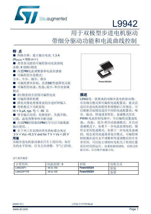
L9942用于双极型步进电机驱动带细分驱动功能和电流曲线控制特点■两路全桥,最大输出电流. 1.3 A(R DSON = 500 mΩ)■带查表功能的可编程驱动电流曲线表格: 9 级5位精度■内置PWM电流调整器和电流传感器■可编程的步进模式:全步、半步、细步、微步■可编程摆率控制:改善EMC性能降低功耗■可编程的高速-, 低速-,混合- 和自动衰减模式■ 3位精度的全范围可编程电流■可编程堵转检测■降低对微处理器要求的步进时钟输入■待机模式下功耗很低IS < 3 μA, typ. Tj ≤85 °C■所有输出均带:短路保护,负载开路,过载,温度预警和热关断功能■内部PWM控制器的PWM信号可以当做数据输出使用。
.■在下列工作范围内所有指标都会保证3 V < Vcc <5.3 V and for 7 V < Vs < 20 V用途双极步进电机驱动器在汽车上的应用:如灯光的水平控制,灯光方向调整,节气门控制。
描述L9942是一款集成的双极步进电机驱动器,具有细分模式和可编程电流配置表,能灵活适应步进电机的特性和预期的工作情况。
可以根据目标情况选用不同的电流配置表:噪音,振动,转速或者转矩。
衰减模式用在PWM-电流控制电路中,可以编程设置成低速-,高速-,混合-和自动衰减模式。
在自动衰减模式下,如果下一步电流是增加的,器件会采用低速模式,如果下一步电流是衰减的,则会采用高速或者混合模式。
可编程堵转检测在前灯水平调整和弯道调整应用中非常有用,可以防止堵转时电机为了转到位置而长时间的运行。
如果检测到堵转,对准过程被关闭,并且噪声被最小化。
表1 器件概要订货代码结温范围°C封装包装方式L9942XP1-40 to 150PowerSSO24 管装L9942XP1TR-40 to 150PowerSSO24 卷带目录1 框图与引脚 . . . . . . . . . . . . . . . . . . . . . . . . . . . . . . . . . . . . . . . . . . . . . . . . . . . . . . . . . . . . 62 器件描述 . . . . . . . . . . . . . . . . . . . . . . . . . . . . . . . . . . . . . . . . . . . . . . . . . . . . . . . . . . . . . . 9 2.1 双电源供电: VS 与 VCC . . . . . . . . . . . . . . . . . . . . . . . . . . . . . . . . . . . . . . . . . . . . . . . . . 9 2.2 待机模式 . . . . . . . . . . . . . . . . . . . . . . . . . . . . . . . . . . . . . . . . . . . . . . . . . . . . . . . . . . . . 9 2.3 诊断功能 . . . . . . . . . . . . . . . . . . . . . . . . . . . . . . . . . . . . . . . . . . . . . . . . . . . . . . . . . . . . 9 2.4 过压与欠压检测 . . . . . . . . . . . . . . . . . . . . . . . . . . . . . . . . . . . . . . . . . . . . . . . . . . . . . . 9 2.5 温度报警与热关断 . . . . . . . . . . . . . . . . . . . . . . . . . . . . . . . . . . . . . . . . . . . . . . . . . . . . 10 2.6 感性负载 . . . . . . . . . . . . . . . . . . . . . . . . . . . . . . . . . . . . . . . . . . . . . . . . . . . . . . . . . . 10 2.7 交叉电流保护 . . . . . . . . . . . . . . . . . . . . . . . . . . . . . . . . . . . . . . . . . . . . . . . . . . . . . . . 10 2.8 PWM 电流调整 . . . . . . . . . . . . . . . . . . . . . . . . . . . . . . . . . . . . . . . . . . . . . . . . . . . . . . 10 2.9 衰减模式 . . . . . . . . . . . . . . . . . . . . . . . . . . . . . . . . . . . . . . . . . . . . . . . . . . . . . . . . . . . 10 2.10 过流检测 . . . . . . . . . . . . . . . . . . . . . . . . . . . . . . . . . . . . . . . . . . . . . . . . . . . . . . . . . 11 2.11 负载开路检测 . . . . . . . . . . . . . . . . . . . . . . . . . . . . . . . . . . . . . . . . . . . . . . . . . . . . . . 11 2.12 步进模式 . . . . . . . . . . . . . . . . . . . . . . . . . . . . . . . . . . . . . . . . . . . . . . . . . . . . . . . . . . 112.13 衰减模式 . . . . . . . . . . . . . . . . . . . . . . . . . . . . . . . . . . . . . . . . . . . . . . . . . . . . . . . . . . 133 电气参数 . . . . . . . . . . . . . . . . . . . . . . . . . . . . . . . . . . . . . . . . . . . . . . . . . . . . . . . . . . . . 14 3.1 绝对最大额定值 . . . . . . . . . . . . . . . . . . . . . . . . . . . . . . . . . . . . . . . . . . . . . . . . . . . . . 14 3.2 ESD 静电保护 . . . . . . . . . . . . . . . . . . . . . . . . . . . . . . . . . . . . . . . . . . . . . . . . . . . . . . 14 3.3 热参数 . . . . . . . . . . . . . . . . . . . . . . . . . . . . . . . . . . . . . . . . . . . . . . . . . . . . . . . . . . . . . 15 3.4 电气特性 . . . . . . . . . . . . . . . . . . . . . . . . . . . . . . . . . . . . . . . . . . . . . . . . . . . . . . . . . . . 16 3.4.1 电源 . . . . . . . . . . . . . . . . . . . . . . . . . . . . . . . . . . . . . . . . . . . . . . . . . . . . . . . . . . . . . 16 3.4.2 过压和欠压检测 . . . . . . . . . . . . . . . . . . . . . . . . . . . . . . . . . . . . . . . . . . . . . . . . . . . . 17 3.4.3 参考电流输出 . . . . . . . . . . . . . . . . . . . . . . . . . . . . . . . . . . . . . . . . . . . . . . . . . . . . . . 17 3.4.4 电荷泵输出 . . . . . . . . . . . . . . . . . . . . . . . . . . . . . . . . . . . . . . . . . . . . . . . . . . . . . . . 18 3.4.5 输出: Qxn (x = A; B n = 1; 2) . . . . . . . . . . . . . . . . . . . . . . . . . . . . . . . . . . . . . . . . . . 183.4.6 PWM 控制 . . . . . . . . . . . . . . . . . . . . . . . . . . . . . . . . . . . . . . . . . . . . . . . . . . . . . . . . 204 SPI的逻辑功能描述 . . . . . . . . . . . . . . . . . . . . . . . . . . . . . . . . . . . . . . . . . . . . . . . . . . . . 21 4.1 电机步进时钟输入 (STEP) . . . . . . . . . . . . . . . . . . . . . . . . . . . . . . . . . . . . . . . . . . . . . 21 4.2 PWM 输出 (PWM) . . . . . . . . . . . . . . . . . . . . . . . . . . . . . . . . . . . . . . . . . . . . . . . . . . . 21 4.3 串行外设接口 (SPI) . . . . . . . . . . . . . . . . . . . . . . . . . . . . . . . . . . . . . . . . . . . . . . . . . . 214.4 芯片反相片选 (CSN) . . . . . . . . . . . . . . . . . . . . . . . . . . . . . . . . . . . . . . . . . . . . . . . . 21 4.5 串行数据输入 (DI) . . . . . . . . . . . . . . . . . . . . . . . . . . . . . . . . . . . . . . . . . . . . . . . . . . 21 4.6 串行数据输出 (DO) . . . . . . . . . . . . . . . . . . . . . . . . . . . . . . . . . . . . . . . . . . . . . . . . . 22 4.7 串行时钟 (CLK) . . . . . . . . . . . . . . . . . . . . . . . . . . . . . . . . . . . . . . . . . . . . . . . . . . . . 224.8 数据寄存器 . . . . . . . . . . . . . . . . . . . . . . . . . . . . . . . . . . . . . . . . . . . . . . . . . . . . . . . 225 SPI –控制和状态寄存器 . . . . . . . . . . . . . . . . . . . . . . . . . . . . . . . . . . . . . . . . . . . . . . . 23 5.1 寄存器 0 . . . . . . . . . . . . . . . . . . . . . . . . . . . . . . . . . . . . . . . . . . . . . . . . . . . . . . . . . 23 5.2 寄存器 1 . . . . . . . . . . . . . . . . . . . . . . . . . . . . . . . . . . . . . . . . . . . . . . . . . . . . . . . . . 24 5.3 寄存器 2 . . . . . . . . . . . . . . . . . . . . . . . . . . . . . . . . . . . . . . . . . . . . . . . . . . . . . . . . . 24 5.4 寄存器 3 . . . . . . . . . . . . . . . . . . . . . . . . . . . . . . . . . . . . . . . . . . . . . . . . . . . . . . . . . 25 5.5 寄存器 4 和 5 . . . . . . . . . . . . . . . . . . . . . . . . . . . . . . . . . . . . . . . . . . . . . . . . . . . . . 25 5.6 寄存器 6 . . . . . . . . . . . . . . . . . . . . . . . . . . . . . . . . . . . . . . . . . . . . . . . . . . . . . . . . . 26 5.7 寄存器 7 . . . . . . . . . . . . . . . . . . . . . . . . . . . . . . . . . . . . . . . . . . . . . . . . . . . . . . . . . 26 5.8 辅助逻辑模块 . . . . . . . . . . . . . . . . . . . . . . . . . . . . . . . . . . . . . . . . . . . . . . . . . . . . . 27 5.8.1 故障条件 . . . . . . . . . . . . . . . . . . . . . . . . . . . . . . . . . . . . . . . . . . . . . . . . . . . . . . . . 27 5.8.2 SPI 通讯监视 . . . . . . . . . . . . . . . . . . . . . . . . . . . . . . . . . . . . . . . . . . . . . . . . . . . . 275.8.3 用于堵转检测的PWM 监视 . . . . . . . . . . . . . . . . . . . . . . . . . . . . . . . . . . . . . . . . . 276 SPI 逻辑的电气特性 . . . . . . . . . . . . . . . . . . . . . . . . . . . . . . . . . . . . . . . . . . . . . . . . 28 6.1 输入: CSN, CLK, STEP, EN 和 DI . . . . . . . . . . . . . . . . . . . . . . . . . . . . . . . . . . . . . 28 6.2 DI 的时序 . . . . . . . . . . . . . . . . . . . . . . . . . . . . . . . . . . . . . . . . . . . . . . . . . . . . . . . . 28 6.3 输出: DO, PWM . . . . . . . . . . . . . . . . . . . . . . . . . . . . . . . . . . . . . . . . . . . . . . . . . . . 29 6.4 输出: DO 的时序 . . . . . . . . . . . . . . . . . . . . . . . . . . . . . . . . . . . . . . . . . . . . . . . . . . . 29 6.5 CSN 的时序 . . . . . . . . . . . . . . . . . . . . . . . . . . . . . . . . . . . . . . . . . . . . . . . . . . . . . . 296.6 STEP 的时序 . . . . . . . . . . . . . . . . . . . . . . . . . . . . . . . . . . . . . . . . . . . . . . . . . . . . . 307 附录 . . . . . . . . . . . . . . . . . . . . . . . . . . . . . . . . . . . . . . . . . . . . . . . . . . . . . . . . . . . . . 33 7.1 堵转检测 . . . . . . . . . . . . . . . . . . . . . . . . . . . . . . . . . . . . . . . . . . . . . . . . . . . . . . . . 33 7.2 步进时钟输入 . . . . . . . . . . . . . . . . . . . . . . . . . . . . . . . . . . . . . . . . . . . . . . . . . . . . . 337.3 负载电流控制和过流检测(输出短路) . . . . . . . . . . . . . . . . . . . . . . . . . . . . . . . . . 338 包装信息 . . . . . . . . . . . . . . . . . . . . . . . . . . . . . . . . . . . . . . . . . . . . . . . . . . . . . . . . 389 历史版本 . . . . . . . . . . . . . . . . . . . . . . . . . . . . . . . . . . . . . . . . . . . . . . . . . . . . . . . . . 39表格列表表 1. 器件概要 . . . . . . . . . . . . . . . . . . . . . . . . . . . . . . . . . . . . . . . . . . . . . . . . . . . . . . . . . . 1表 2. 引脚描述 . . . . . . . . . . . . . . . . . . . . . . . . . . . . . . . . . . . . . . . . . . . . . . . . . . . . . . . . . . 7表 3. 真值表 . . . . . . . . . . . . . . . . . . . . . . . . . . . . . . . . . . . . . . . . . . . . . . . . . . . . . . . . . . . . 11 表 4. 绝对最大额定值 . . . . . . . . . . . . . . . . . . . . . . . . . . . . . . . . . . . . . . . . . . . . . . . . . . . . . 14 表 5. ESD 静电保护 . . . . . . . . . . . . . . . . . . . . . . . . . . . . . . . . . . . . . . . . . . . . . . . . . . . . . . 14 表 6. 工作时的结温 . . . . . . . . . . . . . . . . . . . . . . . . . . . . . . . . . . . . . . . . . . . . . . . . . . . . . . . 15 表 7. 温度报警和热关断. . . . . . . . . . . . . . . . . . . . . . . . . . . . . . . . . . . . . . . . . . . . . . . . . . . . 15 表 8. 电源 . . . . . . . . . . . . . . . . . . . . . . . . . . . . . . . . . . . . . . . . . . . . . . . . . . . . . . . . . . . . . . 16 表 9. 过压和欠压检测 . . . . . . . . . . . . . . . . . . . . . . . . . . . . . . . . . . . . . . . . . . . . . . . . . . . . . 17 表 10. 参考电流输出 . . . . . . . . . . . . . . . . . . . . . . . . . . . . . . . . . . . . . . . . . . . . . . . . . . . . . . 17 表 11. 电荷泵输出 . . . . . . . . . . . . . . . . . . . . . . . . . . . . . . . . . . . . . . . . . . . . . . . . . . . . . . . . 18 表 12. 输出: Qxn (x = A; B n =1; 2) . . . . . . . . . . . . . . . . . . . . . . . . . . . . . . . . . . . . . . . . . . 18 表 13. PWM 控制 (见图 4 和图 7). . . . . . . . . . . . . . . . . . . . . . . . . . . . . . . . . . . . . . . . . . . 20 表 14. 寄存器 0 . . . . . . . . . . . . . . . . . . . . . . . . . . . . . . . . . . . . . . . . . . . . . . . . . . . . . . . . . . 23 表 15. 寄存器 1 . . . . . . . . . . . . . . . . . . . . . . . . . . . . . . . . . . . . . . . . . . . . . . . . . . . . . . . . . . 24 表 16. 寄存器 2 . . . . . . . . . . . . . . . . . . . . . . . . . . . . . . . . . . . . . . . . . . . . . . . . . . . . . . . . . . 24 表 17. 寄存器 3 . . . . . . . . . . . . . . . . . . . . . . . . . . . . . . . . . . . . . . . . . . . . . . . . . . . . . . . . . . 25 表 18. 寄存器 4 和 5 . . . . . . . . . . . . . . . . . . . . . . . . . . . . . . . . . . . . . . . . . . . . . . . . . . . . . . 25 表 19. 寄存器 6 . . . . . . . . . . . . . . . . . . . . . . . . . . . . . . . . . . . . . . . . . . . . . . . . . . . . . . . . . . 26 表 20. 寄存器 7 . . . . . . . . . . . . . . . . . . . . . . . . . . . . . . . . . . . . . . . . . . . . . . . . . . . . . . . . . . 26 表 21. 输入: CSN, CLK, STEP, EN and DI . . . . . . . . . . . . . . . . . . . . . . . . . . . . . . . . . . . . . 28 表 22. DI 的时序 (见图 11 和图 13) . . . . . . . . . . . . . . . . . . . . . . . . . . . . . . . . . . . . . . . . . . 28 表 23. 输出: DO, PWM . . . . . . . . . . . . . . . . . . . . . . . . . . . . . . . . . . . . . . . . . . . . . . . . . . . . 29 表 24. 输出: DO 的时序(见图 12 和图 13) . . . . . . . . . . . . . . . . . . . . . . . . . . . . . . . . . . . . . . 29 表 25. CSN 的时序 . . . . . . . . . . . . . . . . . . . . . . . . . . . . . . . . . . . . . . . . . . . . . . . . . . . . . . . 29 表 26. STEP 的时序 . . . . . . . . . . . . . . . . . . . . . . . . . . . . . . . . . . . . . . . . . . . . . . . . . . . . . . . 30 表 27. 文档历史版本 . . . . . . . . . . . . . . . . . . . . . . . . . . . . . . . . . . . . . . . . . . . . . . . . . . . . . . . 39插图列表图 1. 方框图. . . . . . . . . . . . . . . . . . . . . . . . . . . . . . . . . . . . . . . . . . . . . . . . . . . . . . . . . . . . 6 图 2. 引脚图 (顶视) . . . . . . . . . . . . . . . . . . . . . . . . . . . . . . . . . . . . . . . . . . . . . . . . . . . . . . 6 图 3. 步进模式 . . . . . . . . . . . . . . . . . . . . . . . . . . . . . . . . . . . . . . . . . . . . . . . . . . . . . . . . . 12 图 4. 衰减模式 . . . . . . . . . . . . . . . . . . . . . . . . . . . . . . . . . . . . . . . . . . . . . . . . . . . . . . . . . 13 图 5. 封装的热数据 . . . . . . . . . . . . . . . . . . . . . . . . . . . . . . . . . . . . . . . . . . . . . . . . . . . . . 15 图 6. VS 监视 . . . . . . . . . . . . . . . . . . . . . . . . . . . . . . . . . . . . . . . . . . . . . . . . . . . . . . . . . . 17 图 7. 设置负载电流限制的逻辑 . . . . . . . . . . . . . . . . . . . . . . . . . . . . . . . . . . . . . . . . . . . . . 19 图 8. 最小切换时间 . . . . . . . . . . . . . . . . . . . . . . . . . . . . . . . . . . . . . . . . . . . . . . . . . . . . . . 20 图 9. SPI 与寄存器 . . . . . . . . . . . . . . . . . . . . . . . . . . . . . . . . . . . . . . . . . . . . . . . . . . . . . . 22 图 10. 传输时序图 . . . . . . . . . . . . . . . . . . . . . . . . . . . . . . . . . . . . . . . . . . . . . . . . . . . . . . . 30 图 11. 输入时序 . . . . . . . . . . . . . . . . . . . . . . . . . . . . . . . . . . . . . . . . . . . . . . . . . . . . . . . . . 30 图 12. SPI - DO 有效的数据延迟时间和有效时间 . . . . . . . . . . . . . . . . . . . . . . . . . . . . . . . 31 图 13. DO 使能和禁止时间 . . . . . . . . . . . . . . . . . . . . . . . . . . . . . . . . . . . . . . . . . . . . . . . . 31 图 14. 状态位 0 的时序 (故障条件) . . . . . . . . . . . . . . . . . . . . . . . . . . . . . . . . . . . . . . . . . . 32 图 15. 堵转检测 . . . . . . . . . . . . . . . . . . . . . . . . . . . . . . . . . . . . . . . . . . . . . . . . . . . . . . . . . 35 图 16. PWM 控制的参考产生 (接通) . . . . . . . . . . . . . . . . . . . . . . . . . . . . . . . . . . . . . . . . . 36 图 17. PWM控制的参考产生 (衰减) . . . . . . . . . . . . . . . . . . . . . . . . . . . . . . . . . . . . . . . . . . 37 图 18. PowerSSO24 机械尺寸和包装规格 . . . . . . . . . . . . . . . . . . . . . . . . . . . . . . . . . . . . 381 框图与引脚图图 1. 框图图 2. 引脚图 (顶视)2 芯片描述2.1 双电源供电: VS 和 VCC电源引脚VS脚给半桥供电。
- 1、下载文档前请自行甄别文档内容的完整性,平台不提供额外的编辑、内容补充、找答案等附加服务。
- 2、"仅部分预览"的文档,不可在线预览部分如存在完整性等问题,可反馈申请退款(可完整预览的文档不适用该条件!)。
- 3、如文档侵犯您的权益,请联系客服反馈,我们会尽快为您处理(人工客服工作时间:9:00-18:30)。
第一章安全规定高电压测试前应该注意的规定和事项!!!1.1 一般规定●使用本耐压测试仪以前,请先了解本测试仪所使用的相关安全标志,以策安全。
●在给本耐压测试仪输入电源以前,请对照标牌确认输入电压是否正确。
WARNING CAUTION 123451-----高电压警告符号。
请参考手册上所列的警告和注意说明,以避免人员或仪器受损。
2-----危险标志,可能会有高电压存在,请不要接触。
3-----机体接地符号。
4-----警告应注意所执行的程序、应用或条件均具有很高的危险性,可能导致人员受伤或甚至死亡。
5-----提醒须注意所执行的程序、应用或条件均可能造成仪器损坏或失掉仪器内所有储存的数据。
耐压测试仪所产生的电压和电流足以造成人员伤害或触电,为防止以外伤害或死亡发生,在搬移和使用仪器时,请务必先观察清楚,然后在运行动作。
1.2 维护和保养1.2.1 使用者的维护为了防止触电的发生,请不要拆开测试仪的箱体。
本耐压测试仪内部所有的零件,绝对不需使用者维护。
如仪器有异常情况发生,请与长盛仪器或其指定的经销商联系。
1.2.2 定期维护本耐压测试仪的输入电源线、测试线和相关附件等根据使用频段定期要仔细检验和校验,以保护使用者的安全和仪器的准确性。
1.2.3 使用者的修改使用者不得自行更改仪器内部的线路和零件,如被更改,本公司对仪器的保证自动失效并且本公司不承担任何责任。
使用未经长盛仪器认可的零件或附件也不予保证。
如发现送回的仪器被修改,长盛仪器会将仪器的电路或零件修复回原来的设计状态,并收取维修费用。
1.3 测试工作平台1.3.1 工作台位置工作台的位置选定必须安排在一般人员非必经的场所,使非工作人员远离工作台。
如果因生产线的安排而无法做到时,必须将工作台与其它设施隔开并特别标明“高压测试工作区”。
如果高压测试工作台与其他工作台非常靠近时,必须特别注意安全,以防触电。
在高压测试时,必须标明“危险!正在高压测试,非工作人员请勿靠近”。
1.3.2 输入电源耐压测试仪必须有良好的接地。
本耐压测试仪的后面板上有一接地端,请将此接地端子与大地接触良好。
本耐压测试仪必须有单独的开关,把此开关安装于特别明显的位置并标明其功用。
一旦有紧急事故发生,可以立即关闭电源,以便处理故障。
本耐压测试仪输入电源为交流电源。
电源范围为交流(AC)220V±10%,电源频率为50Hz,在该电源范围内如电源不稳定则有可能造成本耐压测试仪异常动作或损坏测试仪内部元件。
1.3.3 工作测试台在进行耐压测试时,本机必须放在非导电材料的工作台上,操作人员和待测物之间不得使用任何导电材料。
操作人员的位置不得有跨越待测物去操作或调整耐压测试仪的现象。
测试工作区及其周围的空气不能含有可燃气体或在易燃物的旁边使用耐压测试仪,以免引起爆炸和火灾。
1.4 操作人员耐压测试仪所输出电压和电流在错误的操作误触电时,足以造成人员伤亡,因此必须由训练合格的人员使用和操作。
操作人员不可穿有金属装饰的衣服或配带金属的饰物,如手表等。
耐压测试仪绝对不能让有心脏病或配带心脏起搏器的人员操作。
1.5 安全要点·非合格的操作人员和不相关的人员应远离高压测试区。
·随时保持高压测试区在安全和有秩序的状态。
·在高压测试进行中绝对不碰触测试物件或任何与待测物有连接的物件。
·万一发生任何问题,请立即关闭高压输出和输入电源。
·在直流耐压测试后,必须先妥善放电,才能进行拆除测试线的工作。
第二章使用前注意事项本耐压测试仪最高电压可输出6kV,如因任何不正确或错误地使用本耐压测试仪,将会造成意外事故的发生,甚至死亡。
因此为了使用者的安全着想,请详细阅读本章注意事项。
1.防触电为了预防触电事故的发生,在使用本测试仪前,请先戴上绝缘的橡皮手套再从事与电有关的工作。
2.接地在本系列测试仪的后面板上有一接地端子,请将此端子接地。
如果没有可靠的接地,当电源与机壳短路时或者在测试过程中,高压测试线与机壳短路时,机壳都会有高压的存在,这是非常危险的。
只要任何人接触外壳,都有可能造成触电的发生,因此必须将此接地端子可靠的与大地连接。
3.连接测试线与RETURN端将测试线连接于RETURN端,当本测试仪在使用的情况下,任何时候都必须去检查此测试线是否接好、松动或是脱落,当欲用测试线连接测试物时,请先以RETURN端的测试线接上待测物。
如果RETURN端的测试线不完全或脱落是非常危险的。
因整个待测试物上将有可能被充满高电压。
4.连接测试线于高压输出端当连接好RETURN端的测试线,再依下列程序连接高压输出线:●先按下[STOP]键。
●确认测试灯没有亮。
●将高压输出线插入高压输出端上。
5.测试终止当测试已告一段落而不需要使用时,或是本测试仪不再使用时,或在使用中而需离开时,请务必将电源开关置于OFF的位置。
6.测试仪处于测试状态当本测试仪处于测试状态下,测试线、待测物、测试探头和输出端都带有高压,请不要触摸。
注意:不要用手去触摸测试线上的鳄鱼夹,因为当主机测试时,测试线上有高压,鳄鱼夹上的绝缘并不高,触摸会造成触电。
7. 测试完确认在任何时候用手去触摸高压线、被测体或高压输出端,请务必确认:(1)电源开关处于关闭状态,显示器不亮。
(2)当作绝缘测试或直流测试时,被测体在测试完以后有可能有高压存在,此电压在电源开关关闭以后,需要一段时间放电才可能放电完全。
因此刚测试完请不要立即触摸任何可能造成触电的地方。
8. 更换待测物当一个待测物已被测试完毕,更换另一个待测物时,请务必确认:●测试仪处于“复位”状态。
●测试灯不闪烁。
●液晶显示器电压显示数字不在跳动。
特别注意:更换待测物时,请不要用手触摸高压探头!!!9. 启或关闭电源开关一旦电源开关被切断时,如再度开启时,则需等几秒之后,千万不要把电源开关连续做开与关的动作,以免产生错误的动作损坏测试仪。
尤其是当正有高压输出的状态下连续做电源的开与关是非常危险的。
开启或关闭电源时,高压输出端不可连接任何物品以免因不正常高压输出造成危险。
10. 其他注意事项不要使本测试仪的输出线、接地线与传输线或其它连接器的地线或交流电源线短路,以免测试仪整体带电。
11. 危急时处理为了在任何危急的情况下,如触电、待测物燃烧或主机燃烧时,以免造成更大的损失,请按以下步骤处理:●首先切断电源开关。
●将电源线的插头拔掉。
12. 问题的发生在下列情况下,所产生的问题都是非常危险的,即使按下[STOP]键,其输出端仍有可能有高压输出,因此必须非常小心。
●当按下[STOP]键,测试灯仍持续亮着。
●电压表没有电压读值,但测试灯仍亮着。
当发生上述状况时,请立即关掉电源并拔掉电源插头,不要再使用,此故障是非常危险的,请返回本公司或办事处进行维修处理。
13. 测试灯故障当发现按下[START]键后电压表已有读值,但测试灯仍没有亮,此时有可能是测试灯故障,请立即关机,送回本公司或办事处进行维修处理。
14. 测试仪不动作时处理此系列测试仪为耐压测试仪或耐压绝缘测试仪,其输出最大电压为5.000kVac或6.000kVdc;这些测试仪的工作环境非常恶劣,如在使用过程中,测试仪没有任何反应,请关掉电源,等待15秒钟以后再重新打开电源继续使用。
15、泄漏电流、功率、电压启动测试时的注意事项此系列测试仪的泄漏电流、功率、低压启动测试有最大功率限制,开始测试前,请先确认被测试体的功率小于本测试仪最大输出功率;如被测试体的功率大于测试仪的最大输出功率,测试仪提示过载。
第三章功能介绍本系列综合安规测试仪为智能型程控综合安规测试仪,它均采用高速MCU和大规模数字电路设计的高性能的安规测试仪,其输出电压的大小、输出电压的上升、下降、输出电压的频率完全由MCU控制,能实时显示击穿电流值和电压值,并具有软体校准功能,配备PLC所需的信号输入、输出接口,并可选配RS232C或RS485接口,可方便地与计算机或PLC组成综合测试系统。
能够快速、准确地测量电子元器件、家用电器、绝缘材料、仪器仪表、照明电器、电动电热器具的耐压强度。
本系列符合如下标准:家用电器类标准(IEC6035、GB4706.1-2005)、医用类标准(IEC601-1-1998、GB4706.1-1998)、灯具类标准(IEC60598-1-1999、GB7000.1-2000)、信息类标准(GB8898-2001、GB12113、GB4943-2001、IEC60065、IEC60950)等等。
3.1 具有电源安全检测功能本系列安规测试仪为确保操作者的安全,均采用外壳接地的I类工作方式,但当供电电路极性接错(正确接法为左中、右相、上地)会造成机壳带电等危险,本系列测试仪自带电源安全检测功能,在插上电源后(仪器开关处于OFF状态)即能判断出电源的N、L、G有无接错。
如“OK”灯全亮表示电源的接法时正确的,否则电源的接法有误,请不要触摸机壳,机壳可能带电。
3.2采用大屏液晶显示器显示各种参数本系列综合安规测试仪采用大屏320X240图形液晶显示器显示,可显示各种参数,同时在同一界面下可显示所有的设定参数及测试参数。
3.3 具有中文、英文两种语言本系列测试仪具有两种语言:中文、英文;用户可通过主界面下的“系统参数”中的“操作环境参数”设定所使用的语言;⇓“系统参数”⇓“操作环境参数”3.4 自动升压、自动降压3.4.1自动升压用户可根据时间设置电压上升的速度,比如,额定测试电压为1000V,要测试仪每秒上升50V,那么可把电压上升时间设置为20s,如果要测试仪每秒上升200V,那么可把电压上升时间设置为5s。
在电压上升的过程中,如果测试电流大于设置电流的上限,仪器将自动切断输出电压,发出声光提示,并且在显示屏上保留显示当前的电压值和电流值。
这一功能常用来测试或分析被试品的电压击穿点,也可用来测试容性被试品的耐压。
这一功能,是传统耐压测试装置无法实现的。
3.4.2 自动降压用户可根据时间设置电压下降的速度,比如,额定测试电压为1000V,要测试仪每秒下降50V,那么可把电压上升时间设置为20s,如果要测试仪每秒下降200V,那么可把电压上升时间设置为5s。
在电压下降的过程中,如果测试电流大于设置电流的上限,仪器将自动切断输出电压,发出声光提示,并且在显示屏上保留显示当前的电压值和电流值。
3.5 软件校准所有计量仪器,均须定期校准。
传统的方法是,外接标准设备,打开机壳,用工具调整机内元件,使被校仪器参数符合标准。
这种方法往往要反复多次,才能达到目的,拆装过程需专业技术人员操作,比较麻烦。
软件校准,是将标准设备与本机连接后,使仪器进入相应校准状态,然后将标准设备的标准参数用按键输入,按EXIT键退出后即刻完成,方法简单易学,用户自己就能进行,省去了诸多麻烦。