8401-018中文资料
1803-0-15-01-43-27-04-0中文资料

Product Number: 1803-0-15-01-43-27-04-0Description:1803 - Receptacle With AStandard TailAccepts .015-.025 diameter leads.Packaging:Packaged in BulkMill-MaxPartNumberShell Plating Contact Plating RoHS Compliant 1803-0-15-01-43-27-04-0200 - 300 µ" Tin/Lead over Nickel 30 µ" Gold over NickelCONTACT:Contact Used: #43, Ultra Lite Force 6 Finger ContactCurrent Rating = 3 AmpsBERYLLIUM COPPER ALLOY 172 (UNS C17200) perASTM B 194Properties of BERYLLIUM COPPER:Chemical composition: Cu 98.1%, Be 1.9%Temper as stamped: TD01Properties after heat treatment (TH01):Hardness: 36-43 Rockwell CMechanical Life: 100 Cycles Min.Density: .298 lbs/in3Electrical Conductivity: 22% IACS*Resistance: 10 miliohms MaxOperating Temperature: -55°C/+125°CMelting point: 980°C/865°C (liquidus/solidus)Stress Relaxation†: 96% of stress remains after 1,000 hours @ 100 ºC ; 70% of stress remains after 1,000 hours @ 200 ºC*International Annealed Copper Standard, i.e. as a % of pure copper.†Since BeCu loses its spring properties over time at high temperatures; it is rated for continuous use up to 150°C. For applications up to 300°C, Mill-Max offers many contacts in Beryllium Nickel. Contact Tech Support for more info.SHELL MATERIAL:BRASS ALLOY (UNS C36000) per ASTM B 16Properties of BRASS ALLOY:Chemical composition: Cu 61.5%, Zn 35.4%, Pb 3.1%†Hardness as machined: 80-90 Rockwell BDensity: .307 lbs/in3Electrical conductivity: 26% IACS*Melting point: 900°C/885°C (liquidus/solidus)†(3 to 4% lead is used to permit “free machining” and is permitted by EC Directive 2002/95Annex 6; so all pin materials are RoHS compliant)*International Annealed Copper Standard, i.e. as a % of pure copper.。
84091012A中文资料

PACKAGING INFORMATIONOrderable Device Status(1)PackageType PackageDrawingPins PackageQtyEco Plan(2)Lead/Ball Finish MSL Peak Temp(3)5962-8409101VCA ACTIVE CDIP J141None Call TI Level-NC-NC-NC 5962-8409101VDA ACTIVE CFP W141None Call TI Level-NC-NC-NC 84091012A ACTIVE LCCC FK201None Call TI Level-NC-NC-NC 8409101CA ACTIVE CDIP J141None Call TI Level-NC-NC-NC 8409101DA ACTIVE CFP W141None Call TI Level-NC-NC-NC JM38510/65702BCA ACTIVE CDIP J141None Call TI Level-NC-NC-NC JM38510/65702BDA ACTIVE CFP W141None Call TI Level-NC-NC-NC SN54HC14J ACTIVE CDIP J141None Call TI Level-NC-NC-NCSN74HC14D ACTIVE SOIC D1450Pb-Free(RoHS)CU NIPDAU Level-2-260C-1YEAR/Level-1-235C-UNLIMSN74HC14DBR ACTIVE SSOP DB142000Pb-Free(RoHS)CU NIPDAU Level-2-260C-1YEAR/Level-1-235C-UNLIMSN74HC14DR ACTIVE SOIC D142500Green(RoHS&no Sb/Br)CU NIPDAU Level-1-260C-UNLIMSN74HC14DT ACTIVE SOIC D14250Pb-Free(RoHS)CU NIPDAU Level-2-260C-1YEAR/Level-1-235C-UNLIMSN74HC14N ACTIVE PDIP N1425Pb-Free(RoHS)CU NIPDAU Level-NC-NC-NC SN74HC14N3OBSOLETE PDIP N14None Call TI Call TISN74HC14NS ACTIVE SO NS14Pb-Free(RoHS)CU NIPDAU Level-2-260C-1YEAR/Level-1-235C-UNLIMSN74HC14NSLE OBSOLETE SO NS14None Call TI Call TISN74HC14NSR ACTIVE SO NS142000Pb-Free(RoHS)CU NIPDAU Level-2-260C-1YEAR/Level-1-235C-UNLIMSN74HC14PW ACTIVE TSSOP PW1490Pb-Free(RoHS)CU NIPDAU Level-1-250C-UNLIMSN74HC14PWLE OBSOLETE TSSOP PW14None Call TI Call TISN74HC14PWR ACTIVE TSSOP PW142000Pb-Free(RoHS)CU NIPDAU Level-1-250C-UNLIMSN74HC14PWT ACTIVE TSSOP PW14250Pb-Free(RoHS)CU NIPDAU Level-1-250C-UNLIM SNJ54HC14FK ACTIVE LCCC FK201None Call TI Level-NC-NC-NC SNJ54HC14J ACTIVE CDIP J141None Call TI Level-NC-NC-NC SNJ54HC14W ACTIVE CFP W141None Call TI Level-NC-NC-NC (1)The marketing status values are defined as follows:ACTIVE:Product device recommended for new designs.LIFEBUY:TI has announced that the device will be discontinued,and a lifetime-buy period is in effect.NRND:Not recommended for new designs.Device is in production to support existing customers,but TI does not recommend using this part in a new design.PREVIEW:Device has been announced but is not in production.Samples may or may not be available.OBSOLETE:TI has discontinued the production of the device.(2)Eco Plan-May not be currently available-please check /productcontent for the latest availability information and additional product content details.None:Not yet available Lead(Pb-Free).Pb-Free(RoHS):TI's terms"Lead-Free"or"Pb-Free"mean semiconductor products that are compatible with the current RoHS requirements for all6substances,including the requirement that lead not exceed0.1%by weight in homogeneous materials.Where designed to be soldered at high temperatures,TI Pb-Free products are suitable for use in specified lead-free processes.Green(RoHS&no Sb/Br):TI defines"Green"to mean"Pb-Free"and in addition,uses package materials that do not contain halogens, including bromine(Br)or antimony(Sb)above0.1%of total product weight.(3)MSL,Peak Temp.--The Moisture Sensitivity Level rating according to the JEDECindustry standard classifications,and peak solder temperature.Important Information and Disclaimer:The information provided on this page represents TI's knowledge and belief as of the date that it is provided.TI bases its knowledge and belief on information provided by third parties,and makes no representation or warranty as to the accuracy of such information.Efforts are underway to better integrate information from third parties.TI has taken and continues to take reasonable steps to provide representative and accurate information but may not have conducted destructive testing or chemical analysis on incoming materials and chemicals.TI and TI suppliers consider certain information to be proprietary,and thus CAS numbers and other limited information may not be available for release.In no event shall TI's liability arising out of such information exceed the total purchase price of the TI part(s)at issue in this document sold by TI to Customer on an annual basis.元器件交易网元器件交易网IMPORTANT NOTICETexas Instruments Incorporated and its subsidiaries (TI) reserve the right to make corrections, modifications,enhancements, improvements, and other changes to its products and services at any time and to discontinueany product or service without notice. Customers should obtain the latest relevant information before placingorders and should verify that such information is current and complete. All products are sold subject to TI’s termsand conditions of sale supplied at the time of order acknowledgment.TI warrants performance of its hardware products to the specifications applicable at the time of sale inaccordance with TI’s standard warranty. T esting and other quality control techniques are used to the extent TIdeems necessary to support this warranty. Except where mandated by government requirements, testing of allparameters of each product is not necessarily performed.TI assumes no liability for applications assistance or customer product design. Customers are responsible fortheir products and applications using TI components. T o minimize the risks associated with customer productsand applications, customers should provide adequate design and operating safeguards.TI does not warrant or represent that any license, either express or implied, is granted under any TI patent right,copyright, mask work right, or other TI intellectual property right relating to any combination, machine, or processin which TI products or services are used. Information published by TI regarding third-party products or servicesdoes not constitute a license from TI to use such products or services or a warranty or endorsement thereof.Use of such information may require a license from a third party under the patents or other intellectual propertyof the third party, or a license from TI under the patents or other intellectual property of TI.Reproduction of information in TI data books or data sheets is permissible only if reproduction is withoutalteration and is accompanied by all associated warranties, conditions, limitations, and notices. Reproductionof this information with alteration is an unfair and deceptive business practice. TI is not responsible or liable forsuch altered documentation.Resale of TI products or services with statements different from or beyond the parameters stated by TI for thatproduct or service voids all express and any implied warranties for the associated TI product or service andis an unfair and deceptive business practice. TI is not responsible or liable for any such statements.Following are URLs where you can obtain information on other Texas Instruments products and applicationsolutions:Products ApplicationsAmplifiers Audio /audioData Converters Automotive /automotiveDSP Broadband /broadbandInterface Digital Control /digitalcontrolLogic Military /militaryPower Mgmt Optical Networking /opticalnetworkMicrocontrollers Security /securityTelephony /telephonyVideo & Imaging /videoWireless /wirelessMailing Address:Texas InstrumentsPost Office Box 655303 Dallas, Texas 75265Copyright 2005, Texas Instruments Incorporated。
CS8900A中文数据手册 中文部分翻译

Байду номын сангаас 目录
4.10.11 I/O 模式下轮询 CS8900A....................................................................... 15 5.2 基本接收操作........................................................................................................ 17
5.2.1.1 数据包................................................................................................ 17 5.2.1.2 帧........................................................................................................ 17 5.2.1.3 传送.................................................................................................... 18 5.2.2 接收配置...................................................................................................... 18 5.2.2.1 配置物理接口.................................................................................... 19
118JB120R5A0A1中文资料

Resistance Range1 ohm through 20,000 ohms (linear taper) Resistance ToleranceStandard:±20%Special:±10%Power Rating, Watts2 watts @ 55°C derated to no load @ 105°C,linear taper, bushing mounted control onsteel panel 4"x4" x .050"(101.6mm x 101.6mm x 1.27mm).Voltage RatingTerminals to mounting surface (insulated types only):High pot test, one minute — 900 VACOperating Maximum — 500 VDCAcross end terminals:Determined by resistance value andwattage rating Resistance TapersStandard: LinearTaps AvailableNoneIncorporated Fixed ResistorA fixed resistor can be incorporated at the endof CW or CCW rotation to a minimum of 15% ofthe total resistance value. The rotation isshortened by an amount proportional to the ratioof the fixed resistor to the total resistance value. Angle of RotationTotal Rotation: 270°±5°Rotational TorqueTurning Torque: 1/2 to 10 in-oz. (36-720 gf-cm)4 in-oz. (4.61 Kgf-cm)Electrical and Mechanical SpecificationsStop StrengthOrdering InformationTerminal InformationInsulated Construction (Standard)The contactor is insulated from the base and connected to the center terminal on the insulated construction. This construction can be supplied with the center terminal and one end terminal at either end of the resistance element or with the center terminal and terminals at both ends of the resistance element.Grounded Construction (Optional)The grounded construction is supplied without a center terminal and the contactor is connected to the case. This construction can be furnished with one end terminal at either end of the resistance element or with terminals at both ends of the element.Bushing InformationStandard:3/8"-32 UNEF-2A thread, .375" (9.53mm)or .250" (6.35mm) long. M9 x 0.75available.Special:As required in increments of 1/16" (1.58mm) Locating LugsStandard Position:Left side (with terminals down)supplied, unless otherwise specified.Other Positions:Available with right side only, bothleft and right, or without lugs.Electrical and Mechanical SpecificationsCLEARANCE HOLE FOR 3/8-32 THREADED BUSHINGCTS SERIES TYPE 118。
MAX4081SASA+中文资料

Stresses beyond those listed under “Absolute Maximum Ratings” may cause permanent damage to the device. These are stress ratings only, and functional operation of the device at these or any other conditions beyond those indicated in the operational sections of the specifications is not implied. Exposure to absolute maximum rating conditions for extended periods may affect device reliability.
For pricing, delivery, and ordering information, please contact Maxim Direct at 1-888-629-4642, or visit Maxim’s website at .
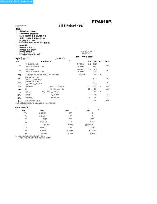
EPA018B中文资料(Excelics Semiconductor)中文数据手册「EasyDatasheet - 矽搜」
6V,半智能决策支持系AG ANG
4.681 169.2 0.010 77.2
4.581 160.2 0.020 71.8
4.476 151.2 0.030 67.3
4.339 142.0 0.037 61.9
4.206 132.9 0.044 54.3
2.852 75.6 0.067 16.4
2.749 69.6 0.069 12.9
2.663 63.4 0.070 9.5
2.585 57.1 0.071 6.7
2.515 50.6 0.074 3.4
2.423 44.1 0.076 0.2
2.341 37.4 0.079 -2.4
2.254 30.8 0.081 -6.3
芯片中文手册,看全文,戳
已发行 11/01/2007
高效率异质结功率FET
EPA018B
特征 非 常 高 fmax: 120GHz + 20.0dBm典型输出功率 13.0分 贝 典 型 功 率 增 益 为 18千 兆 赫 典 型 0.75分 贝 噪 声 系 数 和 12.5分 贝 相关增益AT 12GHz 0.3×180 MICRON RECESSED"蘑菇 "门 Si3N4 钝化
- S11 MAG ANG 1.000 -11.0 0.990 -21.5 0.976 -32.1 0.962 -42.6 0.941 -53.4 0.922 -63.6 0.905 -73.1 0.883 -82.0 0.864 -90.4 0.846 -97.9 0.829 -105.3 0.819 -112.4 0.804 -120.0 0.792 -128.0 0.784 -136.3 0.777 -145.0 0.770 -155.2 0.773 -165.3 0.770 -175.2 0.771 175.3 0.780 169.2 0.777 163.2 0.793 157.9 0.789 154.9 0.796 151.5 0.804 149.6 0.786 147.6 0.788 146.0 0.779 144.4 0.777 140.9 0.769 137.1 0.770 131.7 0.758 126.2 0.764 120.0 0.777 114.3 0.799 107.4 0.824 101.9 0.856 97.2 0.877 92.4 0.884 89.0
CS8401中文资料
Specifications are subject to change without notice.
2
DS60F1
元器件交易网
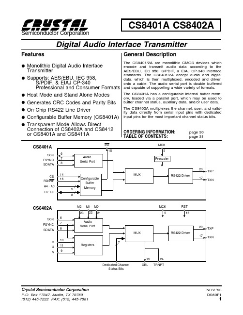
CS8401A CS8402A
DIGITAL CHARACTERISTICS - RS422 DRIVERS
(TXP, TXN pins only; VD+ = 5V ±10%)
Professional and Consumer Formats and capable of supporting a wide variety of formats.
• Host Mode and Stand Alone Modes • Generates CRC Codes and Parity Bits
元器件交易网
CS8401A CS8402A
SWITCHING CHARACTERISTICS - SERIAL PORTS
(TA = 25 °C for suffixes ’-CP’ and ’-CS’; TA = -40 to 85 °C for suffixes ’-IP’ and ’-IS’; Inputs: Logic 0 = GND, logic 1 = VD+; CL = 20 pF)
Note 2
IDD
1.5
5
Ambient Operating Temperature: CS8401/2A-CP or -CS Note 3
TA
CS8401/2A-IP or -IS
0
25
70
-40
85
Power Consumption
Note 2
PD
7.5
25
Notes:
1-1393480-8中文资料

1-1393480-8 Product DetailsHome | Customer Support | Suppliers | Site Map | Privacy Policy | Browser Support© 2008 Tyco Electronics Corporation All Rights Reserved SearchProducts Documentation Resources My Account Customer Support Home > Products > By Type > D Subminiature > Product Feature Selector > Product Details1-1393480-8 (V23529B1121B215) TE Part Number: 1-1393480-8ActiveAdd to Part List Standard Board Mount ConnectorsAlways EU RoHS/ELV Compliant (Statement of Compliance)Product Highlights:?Number of Positions = 15?Receptacle?PCB Mount Angle = Right Angle?Product Series = HD 20 Type B -Solder Terminal?Without Mating Connector LockView all Features | Find SimilarProductsCheck Pricing &AvailabilitySearch for ToolingView MatingProducts (7)Product FeatureSelectorContact Us AboutThis ProductRequest SamplesQuick LinksDocumentation & Additional InformationProduct Drawings:?D-Sub 90? solder female (mounting height 3.6 mm)(PDF,English)Catalog Pages/Data Sheets:?COMMUNICATION PRODUCTS ADDENDUM(PDF, English)?AMPLIMITE SUBMINATURE D TYPE CONNECTORS(PDF, English) ?AMPLIMITE Subminiature D Connectors -Right-Angle Po...(PDF, English)Product Specifications:?None AvailableApplication Specifications:?None AvailableInstruction Sheets:?None AvailableCAD Files:?None AvailableList all Documents Additional Information:?Product Line InformationAdditional Product Images: ?Schematic?PCB LayoutRelated Products:?Tooling?Mating Products (7)Product Features (Please use the Product Drawing for all design activity)Product Type Features:?Number of Positions = 15?Gender = Receptacle?PCB Mount Angle = Right Angle?Product Series = HD 20 Type B -SolderTerminal?Mating Connector Lock = Without?PCB Retention Feature = Yes?Shell Type = Full Metal?Shell Size = 2?Footprint (mm [in]) = 10.70 [.421]?PCB Thickness (in [mm]) = 0.062 [1.57]?Grounding Indents = Without?Grounding Straps = Without?PCB Mount Style = Thru Hole?Color Code = None?Sealed = No?Profile = Eurostyle -3.6 mm Installation Height?Post Size (mm [in]) = 0.70 [.028]?Color = Gray?Shell Material = Steel?Comment = Connectors are preloaded withcontacts.Mechanical Attachment:?Panel Attachment = WithoutTermination Related Features:?Grounding Clips = Without?Termination (Solder) Post Length (mm [in]) =3.20 [0.126]?Solder Tail Contact Plating = Tin Body Related Features:?PCB Retention Method = Mounting Holes?Insert Flammability Rating = UL 94V-0?Insert Material = PBTP -Glass Fiber-ReinforcedThermoplastic?Shell Plating = Tin over Nickel?Mounting Bracket(s) = WithContact Related Features:?Contact Mating Area Plating Material = Gold(30)?Contact Shape = Round?Contact Material = Copper Alloy?Mounting Bracket Insulation = WithoutIndustry Standards:?RoHS/ELV Compliance = RoHS compliant, ELVcompliant?Lead Free Solder Processes = Wave soldercapable to 240°C, Wave solder capable to 260°C, Wave solder capable to 265°C?RoHS/ELV Compliance History = Always wasRoHS compliantOperation/Application:?Application = StandardOther:?Brand = AMPProvide Website Feedback | Need Help?。