NRB-XS470M200V12.5X20F中文资料
433MHz 470MHz贴片型无线模块 E49-400M20S使用手册

E49-400M20S产品规格书433MHz/470MHz贴片型无线模块目录第一章概述 (3)1.1简介 (3)1.2特点功能 (3)1.3应用场景 (3)第二章规格参数 (3)2.1极限参数 (3)2.2工作参数 (4)第三章机械尺寸与引脚定义 (5)第四章基本操作 (6)4.1硬件设计 (6)4.2软件编写 (6)第五章基本应用 (7)5.1基本电路 (7)第六章常见问题 (8)6.1传输距离不理想 (8)6.2模块易损坏 (8)6.3误码率太高 (8)第七章焊接作业指导 (9)7.1回流焊温度 (9)7.2回流焊曲线图 (9)第八章相关型号 (10)第九章天线指南 (10)9.1天线推荐......................................................................................................................错误!未定义书签。
修订历史......................................................................................................................................错误!未定义书签。
关于我们......................................................................................................................................错误!未定义书签。
第一章概述1.1简介E49-400M20S是成都亿佰特推出的一款高性价比无线数传模块,它是一款基于CMT2300A的纯硬件模块。
E49-400M20S支持最大20dBm发射功率,用户可设置更低输出功率,从而节省功耗。
柔性检查作用域套件-USB 产品说明书
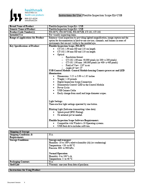
lInstructions for Use: Flexible Inspection Scope Kit-USB Brand Name of ProductFlexible Inspection Scope Kit - USB Generic Name of ProductFlexible Inspection Scope Kit - USB Product Code Number(s)FIS-007U, FIS-007USK, FIS-007UB, CT-101, CT-102Intended UseFor visually inspecting items.Range of Applications for ProductEnhance visual inspection by providing lighted magnification, image capture and the option for documentation in hard-to-see crevices, channels, and lumens in areas of instruments that are not visible to the unaided eye.Key Specifications of Product Flexible Inspection Scope- FIS-007U∙CT-101 1.90 mm OD and 110 cm length∙CT-102 1.06 mm OD and 110 cm length∙Opticalo Resolution format:o CT-102 1.06 mm: 40,000 pixels (or 200- x 200 pixels)o CT-101 1.90 mm: 160,000 pixels (or 400- x 400 pixels)o Field of View: 120° in airo Angle of view: 0°USB Control Module: Control Module housing Camera processor and LEDillumination:∙Dimensions: 5.25- x 3.90- x 1.85 inches∙Weight: 1.20 pounds ∙Digital Inspection Scope Connection∙Illumination Control- LED in the Control Module∙Power Cycle∙USB Camera Cable∙Easily change from small and large diameter scopes.Light Settings:There are four light settings operated by one button.Blinking Light (Indicates transmitting video data):∙Splash proof (IPX5 Rating)∙No external power needed.Flexible Inspection Scope Software Requirements:∙Compatible with Windows 10 Operating systems.∙USB flash drive includes software.Unpacking Flexible Inspection Scope:Carefully inspect for shipping damage. If there is any damage contact the shipping carrier and Heatlhmarkcustomer service 800-521-6224 immediately.USB Control Module: (Fig. 1).1.Digital Inspection Scope Connection 2.Illumination Control 3.Power Cycle B (Type C) on the right side of the boxFigure 1Flexible Inspection Scope™: (Fig. 2).∙CT-101 1.90 mm O.D. and 110 cm length ∙CT-102 1.06 mm O.D. and 110 cm lengthLarge1.90 mmSmall 1.06 mmFigure 2Flexible Inspection Scope™ Features3214Light/Illumination Settings: (Fig. 3).∙Five (5) light settingso Light on control indicats setting levelo Fifth setting is OFF∙Press light button to advance to next setting.∙Fifth setting turns the light OFF.Figure 3Power Cycle ButtonPress button to RESET camera (Fig. 4).Figure 41.Flexible Inspection Scope™ Plug (Fig. 5).Contains camera video connection as well as LED Light for illumination.1Figure 52.Flexible Working Length (Fig. 6).The portion of the Flexible Inspection Scope™ that is inserted into an item during visual inspection.The measuring scale markings on the Flexible Working Length are in centimeters (accuracy = ± 0.5 cm)2Figure 63.Distal Camera (Fig. 7).Distal portion of Flexible Inspection Scope™ that contains the camera lens3Figure 7SOFTWARE INSTALLATION:Note: This section is done only once when connecting the scope to the computer for the first time.∙System Requirements: MS Windows 10∙Install the Flexible Inspection Scope™ Software from the USB flash drive on a computer.Note: If you have any IT policies that may block this installation, please contact your IT team to give access to Healthmark scope viewer to install.1. Insert the USB Flash drive into your computer, and double click on the Healthmark Scope Viewer installer package to begin installation.2. The “Welcome to the Healthmark Scope Viewer Setup Wizard” screen pops up. Click on Next.3. Select the first tab Typical or setup type of your choice, click Next.4. Click Install and wait for installation to complete.5. Click Finish.STARTING SOFTWARE & CONNECTING SCOPE TO PC:(Fig 8).1.Open the Windows PC viewer software.2.Connect the Control Module to PC using USB Cable.3.Plug the Flexible Inspection Scope into the Control Module.4.In the viewer software, click Settings and Select USB Video Device, click on the desiredresolution, select the preferred Video Output Format, and then Click OK.5.Press the Power Cycle Button.Figure 86.Now you can start using the scope.Verifing OperationFollowing the steps listed below will ensure the proper use and performance of the Flexible Inspection Scope™. The Flexile Inspection Scope™ can be checked for normal operation by connecting it as described in the Startup section of this IFU.Normal operation includes:∙An image appearing on your computer monitor or HDMI Monitor.∙ A blinking light on Control Module near the Power Cycle button that indicates the image feed is transmitting.∙White light emitting from the distal end of the Digital Inspection Scope.∙An LED light on the control module top panel that indicates the light intensity of the device. Using SoftwareHealthmark Scope Viewer Software (Fig. 9).1.Capture button: Captures a Reference Image and saves it to the Reference Image folder.2.Main Image Window: Displays the image from the camera.3.Reference Image Window: Displays a reference image.4.Clear Button: Removes the image from the Reference image window.5.Open Reference Image button: Allows selection of a reference image from the Reference Imagefolder.6.Settings Button: Click to select the video camera and resolution settings.7.File Location Button: Click to change location where captured images are being saved.8.File Location Window: Shows the file path where captured images are being saved currently.9.Capture Image Button: Captures images and adds them to the File Location selected by the user(as shown in the File Location Window).10.Capture Video button: Click to record video. Click again to stop recording video.11.File Prefix: Type in text that you would like included in the file name of Captured Images.Figure 9Selecting Video Device or CameraFollow the directions below to select the video device or camera used to capture images using the Flexible Inspection Scope™ Viewer Software. (Fig. 10).1.Click Settings button in the lower left of the Scope Viewer software to display a list of videodevices or cameras being detected by your computer2.Select a device for capturing images using the Scope Viewera.The example below shows a webcam and USB Video Device in the Settings box. Select theUSB Video Device for the Flexible Inspection Scope™.b.You can also select your preferred Video Output Format from the dropdown box3.Click OK to view the selected Video Device.231Figure 10Capturing Still PicturesFollow the instructions for capturing still pictures from the Main Image Window.Select the Capture Image button. (Fig. 11).Figure 11Note: When an image is captured, “Image Captured” in red text will flash on the lower portion of the screen and a new file will appear in the Files Location.Capturing Video ImagesFollow the instructions below for capturing video from the Main Image Window.1.Select the Capture Video Button (Fig. 12).Figure 122.When the video is recording “Recording…” in red text will appear toward the bottom of thesoftware window.3.To stop recording, click Stop Capture. (Fig. 13).Figure 13Setting File PrefixFollowing the steps below allows you to create a file prefix that will appear after the underscore of image file names save to the File Location specified by the user.1.Click in the field next to File Prefix.2.Enter the characters that you would like to be included in the file name. (Fig 14).Figure 14Setting Location for Saved FilesFollowing the steps below allows you to set the file location of saved images using the Scope Viewer software.1.Click the File Location button.2.Select the file location you want to save captured images. (Fig 15).Figure 15Displaying Reference ImageThere are two ways to display a still image in the Reference Image Window on the Scope Viewer software.1.To display an image currently being displayed in the Main Image Window, click the Capture button. Note: The images will be saved in a file folder titled Reference Images in the designated File Location that the user specified in the File Location field. (Fig. 16).Figure 162.To display a saved image in the Reference Image Window from your File Location:a.Click the Open Reference Image button (Fig. 16 above).b.Select the file you want to display (Fig. 17 below).c.Click the OK Button, to display the image in the Reference Image Window. (Fig. 17).Figure 17Switching to a Different Flexible Inspection Scope™ on the Control Module:1.Press the Power button on the Control Module once.2.Disconnect the current Flexible Inspection Scope from the Control Module.3.Repeat the steps in the “STARTING SOFTWARE & CONNECTING SCOPE TO PC” procedure.Inserting Scope in ItemFigure 1Rotating Device to Avoid ObstacleFigure 2 Performing InspectionWipe down the Flexible Inspection Scope™ with a compatible wipe. Follow the manufacturer’s (Mfr.’s)Instructions for Use (IFU) for appropriate wipe usage. Click here to see the Chemical Compatibility Chart(PDF) for approved cleaning.The Flexible Inspection Scope™ is made of the same material as other common endoscopes. Any wipe,solution, or low temperature (≤ 60 °C [140 °F]) method intended for the reprocessing of endoscopes is likelycompatible with the Generation II Flexible Inspection Scope™ Catheters if used according to the productlabeling.Solutions Containing (Flexible Inspection Scope Only)Alcohol Ethoxylates Neutral or Near-Neutral pH DetergentsEnzymatic Cleaning Solutions Enzymatic DetergentsSodium Borated, Decahydrate Tetrapotassium PyrophosphateFlexible Inspection Scope™ has a fluid ingress protection rating of IPX7 (Waterproof) and can withstandimmersion in fluid up to one (1)-meter in depth for up to 30 minutes.Control Module USB has a fluid ingress protection rating of IPX5 (Water resistant) and can withstand asustained, low pressure water jet spray for up to three minutes.For Thorough Cleaning: CablesFollow the cleaning agent Mfr.’s IFU.1.Unplug and disconnect all components from the Control box prior to cleaning.2.Do not submerge or soak the cable for disinfection (cable is not waterproof).3.Wipe thoroughly with non-linting wipe moistened with facility approved neutral detergent. Use theappropriate brushes with detergent solution to remove any residues from areas that cannot bereached with the wipes.For Thorough Cleaning: Control Module1.Unplug and disconnect all components from the Control box prior to cleaning.2.Do not submerge or soak the cable for disinfection (Control Box is not waterproof).3.Wipe thoroughly with non-linting wipe moistened with facility approved neutral detergent. Use theappropriate brushes with detergent solution to remove any residues from areas that cannot bereached with the wipes.Note: Do NOT soak. Control Module and cables are not waterproof and should not be immersed.N/ACleaning –AutomatedDisinfection Control Module and CablesThese may be cleaned with alcohol based disinfectant wipes.Compatible agents (wipes and solutions) for disinfecting Flexible Inspection Scope™ and ControlModule:∙Hydrogen peroxide∙Isopropyl alcohol (IPA)∙Sodium hypochlorite (Bleach)∙Ortho-phenylphenol∙Quaternary ammonium.High-Level Disinfection (Flexible Inspection Scope™ Only)∙Select only disinfecting solutions listed in the compatible disinfecting methods.∙Follow all recommendations regarding health-hazards, dispensing, measuring, and storage from the Mfr. of cleaning and disinfecting agents.∙Soak the Flexible Inspection Scope™ in selected disinfecting solution per Mfr.’s IFU.∙Rinse the Flexible Inspection Scope™ with critical (sterile) water, again, following the disinfecting solutions Mfr.’s instructions.Reprocessing Chemical Compatibility Chart (PDF): Click here.。
RVT贴片铝电解电容470UF35V 10X10规格书
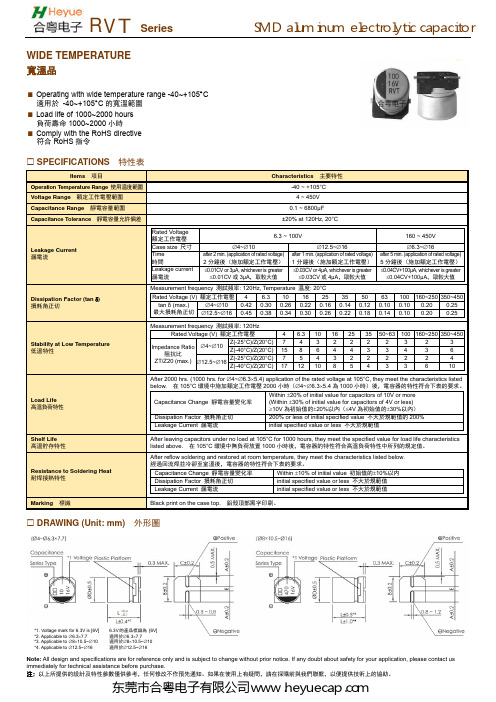
Note: All design and specifications are for reference only and is subject to change without prior notice. If any doubt about safety for your application, please contact us immediately for technical assistance before purchase.注: 以上所提供的設計及特性參數僅供參考,任何修改不作預先通知。
如果在使用上有疑問,請在採購前與我們聯繫,以便提供技術上的協助。
WIDE TEMPERATURE寬溫品Operating with wide temperature range -40~+105°C 適用於 -40~+105°C 的寬溫範圍 Load life of 1000~2000 hours 負荷壽命1000~2000小時Comply with the RoHS directive 符合RoHS 指令SPECIFICATIONS 特性表Items 項目Characteristics 主要特性Operation Temperature Range 使用温度範圍 -40 ~ +105°C Voltage Range 額定工作電壓範圍 4 ~ 450V Capacitance Range 靜電容量範圍 0.1 ~ 6800μF Capacitance Tolerance 靜電容量允許偏差±20% at 120Hz, 20°C Leakage Current 漏電流Rated Voltage 額定工作電壓 6.3 ~ 100V160 ~ 450VCase size 尺寸 ∅4~∅10∅12.5~∅16∅6.3~∅16Time 時間after 2 min. (application of rated voltage)2分鐘後(施加額定工作電壓)after 1 min. (application of rated voltage) 1分鐘後(施加額定工作電壓) after 5 min. (application of rated voltage)5分鐘後(施加額定工作電壓)Leakage current 漏電流≤0.01CV or 3μA, whichever is greater ≤0.01CV 或3μA ,取較大值≤0.03CV or 4μA, whichever is greater ≤0.03CV 或4μA ,取較大值≤0.04CV+100μA, whichever is greater ≤0.04CV+100μA ,取較大值Dissipation Factor (tan δ) 損耗角正切Measurement frequency 測試頻率: 120Hz, Temperature 温度: 20°C Rated Voltage (V) 額定工作電壓 4 6.31016253550 63 100 160~250350~450tan δ (max.) 最大損耗角正切 ∅4~∅100.420.300.260.220.160.14 0.12 0.10 0.100.20 0.25 ∅12.5~∅160.450.380.340.300.260.22 0.18 0.14 0.100.20 0.25Stability at Low Temperature低溫特性Measurement frequency 測試頻率: 120HzRated Voltage (V) 額定工作電壓 4 6.3101625 35 50~63 100160~250350~450Impedance Ratio 阻抗比ZT/Z20 (max.) ∅4~∅10Z(-25°C)/Z(20°C)7 4 3 2 2 2 2 3 2 3Z(-40°C)/Z(20°C)158 6 4 4 3 3 4 3 6∅12.5~∅16Z(-25°C)/Z(20°C)7 5 4 3 2 2 2 2 2 4Z(-40°C)/Z(20°C)1712108 5 4 3 3 6 10 Load Life 高溫負荷特性After 2000 hrs. (1000 hrs. for ∅4~∅6.3×5.4) application of the rated voltage at 105°C, they meet the characteristics listedbelow. 在105°C 環境中施加額定工作電壓2000小時(∅4~∅6.3×5.4為1000小時)後,電容器的特性符合下表的要求。
Siemens PAT系列产品说明书

This publication was produced on the Siemens 5800 Office System. Subject to change without prior notice. The reproduction, transmission or use of this document or its contents is not permitted without express written authority. Offenders will be liable for damages. All rights, including rights created by patent grant or registration of a utility model or design, are reserved.
siemens
Equipment for special machines
WF 470 Video Display Module
Description
Edition 08.91
siemens
NRB-XS470M450V12.5x35F中文资料
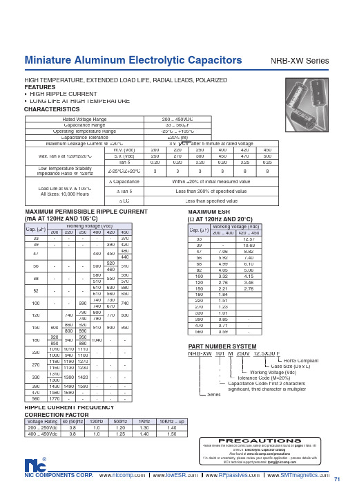
71®NIC COMPONENTS CORP. www www www www Rated Voltage Range 200 ~ 450VDC Capacitance Range33 ~ 560µF Operating Temperature Range-25°C ~ +105°C Capacitance Tolerance±20% (M)Maximum Leakage Current @ +20°CMax. Tan δ at 120Hz/20°CW.V . (Vdc)200220250400420450S.V . (Vdc)250270300450470500Tan δ0.200.200.200.200.250.25Low Temperature StabilityImpedance Ratio @ 120HzZ-25°C/Z+20°C333888Load Life at W.V . & 105°C All Sizes: 10,000 Hours∆ CapacitanceWithin ±20% of initial measured value ∆ Tan δLess than 200% of specifi ed value∆ LCLess than specifi ed value3 x CV after 5 minute at rated voltageCap. (µF)Working Voltage (Vdc)20022025040042045033-----37039----39042047---44045048044056---50052051046068---58055059051057082---610630680610560650100--690740730740740670120-7407908007708307407901508008609209109009508008901809209409501040--850880220101010101110---10009401100270118011901270---116011301230330131013001420---1300390143014901590---47015801690----5601770-----MAXIMUM PERMISSIBLE RIPPLE CURRENT(mA AT 120Hz AND 105°C)Miniature Aluminum Electrolytic CapacitorsNRB-XW SeriesMAXIMUM ESR(Ω AT 120Hz AND 20°C)PART NUMBER SYSTEMNRB-XW 101 M 250V 12.5X30F .φ x L) signifi cant, third character is multiplier SeriesCapacitance Code: First 2 characters T olerance Code (M=20%)Working Voltage (Vdc) Case Size (D RoHS CompliantCHARACTERISTICSHIGH TEMPERATURE, EXTENDED LOAD LIFE, RADIAL LEADS, POLARIZED FEATURES• HIGH RIPPLE CURRENT• LONG LIFE AT HIGH TEMPERATURE Voltage Rating 60 (50)Hz 120Hz500Hz 1KHz 10KHz ~ up200 ~ 250Vdc 0.8 1.0 1.20 1.30 1.40400 ~ 450Vdc 0.81.01.251.401.50RIPPLE CURRENT FREQUENCY CORRECTION FACTORPRECAUTIONSPlease review the notes on correct use, safety and precautions found on pages T10 & T11of NIC’s Electrolytic Capacitor catalog . Also found at /precautionsIf in doubt or uncertainty, please review your specifi c application - process details withNIC’s technical support personnel: tpmg@Cap. (µF)Working Voltage (Vdc)200 ~ 400420 ~ 45033-12.5739-10.63477.068.8256 5.927.4068 4.99 6.1082 4.05 5.06100 3.32 4.15120 2.76 3.46150 2.21 2.76180 1.84-220 1.51-270 1.23-330 1.01-3900.85-4700.71-5600.59-72®NIC COMPONENTS CORP. www www www www Cap. (µF)Code Working Voltage (Vdc)20022025040042045033330-----12.5x3039390----12.5x3012.5x3547470---12.5x3012.5x35 2.5x4016x2556560---12.5x3512.5x4016x3016x2568680---12.5x4016x3016x3516x2518x2582820---16x3016x3516x4018x2518x2518x30100101--12.5x3016x3516x4018x3518x3018x30120121-12.5x3012.5x3516x4018x3518x4016x2518x3515015112.5x3012.5x3512.5x4018x4018x4018x4516x2516x3018018112.5x3516x3016x3018x45--16x2518x2522022116x3016x3016x35---18x2518x2518x3027027116x3516x3516x40---18x3018x3018x3533033116x4018x3518x40---18x3039039118x3518x4018x45---47047118x4018x45----56056118x45-----STANDARD PRODUCT AND CASE SIZE TABLE D φ x L (mm)LEAD SPACING AND DIAMETER (mm)d φ ± 0.05Insulation Sleeve F ± 0.5D φ ± α4mmMin.15mm Min.L + β max.Polarity MarkingCase Dia. (D φ)12.51618Lead Dia. (D φ)0.60.80.8Lead Spacing (F) 5.07.57.5Dim. α0.50.50.5Dim. β2.5 2.5 2.5Miniature Aluminum Electrolytic CapacitorsNRB-XW Series。
NR200电脑色差仪说明书_2012-12-06

目录概述 (1)注意事项 (1)一.按键功能说明 (2)二、接口说明 (3)三、电池说明及其安装 (4)四、 NR200仪器操作说明 (6)(一)开机 (6)1、开机前准备 (6)2、开机 (6)3、白校正及黑校正 (6)(二)测量 (7)1、定位及测量样品的方法 (7)2、标样测量 (8)3、试样测量 (9)(三)保存数据 (9)1、自动保存 (9)2、手动保存 (10)(四)NR200与PC的通信 (10)(五)打印 (11)五、系统功能说明 (12)1.查看记录及标样调入 (12)2.黑白校正 (14)3、容差设置 (15)4、启动通讯 (15)5、数据删除 (16)6、语言选择 (18)7、显示模式 (19)8、平均测量 (20)9、功能设置 (21)六、产品参数 (27)1、产品特点 (27)2、产品规格 (28)附录 (29)1、物体颜色 (29)2、人眼对颜色的分辨 (29)概述NR200电脑色差仪是依据CIE(国际照明委员会)标准、国家标准而研制开发的高精度电脑色差仪,是一款使用方便、测量快速且性能稳定、测量精准的电脑色差仪。
本色差仪既可使用锂电池供电,也可使用DC外部电源供电。
NR200色差仪开机不需要进行黑白校正,极大的简化测量步骤。
NR200色差仪采用光照光斑定位,方便、迅速地实现对准。
NR200色差仪采用更复杂的高级算法,测量性能更稳定、精准。
注意事项●本产品属于精密测量仪器,在测量时,应避免仪器外部环境的剧烈变化,如在测量时应避免周围环境光照的闪烁、温度的快速变化等;●在测量时,应保持色差仪稳定、测量口贴紧被测物体,并避免晃动、移位;本仪器不防水,不可在高湿度、或水中使用;●保持色差仪整洁,避免水、灰尘等液体、粉末或固体异物进入测量口径内及仪器内部,应避免对色差仪的激烈撞击、碰撞;●色差仪不使用时,应将色差仪、白板盖放进仪器箱,妥善保存;●若长期不用色差仪,应卸下电池,以防止损害色差仪;●色差仪应存放在干燥、阴凉的环境中;●用户不可对本色差仪做任何未经许可的更改。
PNA4702M中文资料

PNA4702M
Block Diagram
VCC (100 kΩ) Amplifier AGC BPF Demodulator Comparator RL VO
PD
Controler
Integrator
GND
Panasonic Transmitter Specifications
LED transmitter unit PNZ323B 20 cm 10 kΩ VO 55 mV Standard receiver unit 10 kΩ 10 µF VO 10 kΩ GND 10 V
*2
Symbol VCC VOL VOH ICC Lmax TWL TWH fO
Conditions L ≤ 7 m, IOL = 400 µA IOH = –2 µA
Min 2.7 2.86 0.6 7.0
Typ 3.3 0.1 3.3 0.8 400 38.0
Max 3.6 0.3 1.0 600
Note) *: Less than 5 s
Symbol VCC PD Topr Tstg Tsol
Rating – 0.5 to +5 200 –15 to +70 –40 to +100 260
Unit V mW °C °C °C
(5°)
1.0±0.15 3-0.45-0.15
+0.25
1
2
3 (2-2.54)
Unit: mm
7.0±0.2 Not soldered 1.5 1.5max. (3.5) (2.25) 5.25±0.3
Features
Center frequency fO : 38 kHz Operating supply voltage VCC : 3.3 V(typ.) Adoption of visible light cutoff resin
rewiew

区域控制器RF-NX80场内控制器RF-NX83通道控制器RF-PX50/RF-PX50P门禁控制器RF-AX50NT2/NT4 RF-AX50PNT2/NT4增强版门禁RF-AX20NT2/NT4 RF-AX20PNT2/NT4门禁一体机RF-AD70/RF-AD70K/RF-AD70DK门禁读卡器RF-RD20/RF-RC20 RF-RD40/RF-RC40 RF-RD40K/RF-RC40K RF-RU40RF-RD70/RF-RC70 RF-RD70K/RF-RC70K RF-RD70DK/RF-RC70DK RF-RC70-SIM RF-RD90/RF-RC90 RF-RD91/RF-RC91 RF-RD92/RF-RC92挡车器RF-B315N RF-B355 RF-B360吐、吞票箱RF-PB12A-C/RF-PB12B-C RF-PB60A/60B RF-PB61A/61B RF-PB80A/80B RF-PB81A/81B自助收费终端RF-ACM/RF-ACM10嵌入式门禁控制器RF-AC10/AD10通道设备RF-BA20/RF-BA30/RF-BA40/RF-BA50 立式摆闸,三辊闸,摆闸,翼闸政府机关,企事业单位,智能社区,智能大厦,数字化校园。
车辆出入口管理系统(停车管理系统,数字引导系统,取车查询系统)人员出入口管理(访客系统,售检票管理系统,门禁系统,梯控系统)智能一卡通(手机一卡通,巡更管理系统,消费管理系统,水控管理系统,考勤管理系统)政府机关,企事业单位,智能大厦,智能社区,数字化校园车辆出入口管理系统(停车管理系统,数字引导系统,取车查询系统)人员出入口管理(访客系统,门禁系统,梯控系统,售检票系统)智能一卡通(手机一卡通,巡更系统,消费系统,水控系统,考勤系统)政府机关,企事业单位,智能社区,智能大厦,数字化校园车辆出入口管理(停车管理系统,数字引导系统,取车查询系统)人员出入口管理(门禁系统,梯控系统,访客系统,售检票系统)智能一卡通(手机一卡通,巡更系统,水控系统,消费系统,考勤系统)。
- 1、下载文档前请自行甄别文档内容的完整性,平台不提供额外的编辑、内容补充、找答案等附加服务。
- 2、"仅部分预览"的文档,不可在线预览部分如存在完整性等问题,可反馈申请退款(可完整预览的文档不适用该条件!)。
- 3、如文档侵犯您的权益,请联系客服反馈,我们会尽快为您处理(人工客服工作时间:9:00-18:30)。
Polarity Marking Insulation Sleeve
dφ ± 0.05
F ± 0.5
L + β max.
15mm Min.
4mm Min.
Dφ ± α
®
NIC COMPONENTS CORP. 70
MAXIMUM PERMISSIBLE RIPPLE CURRENT
(mA AT 100KHz AND 105°C)
Cap. (µF) 160
Working Voltage (Vdc) 200 250 350 400
450
1.0
-
-
-
-
60 70
-
1.5
-
-
-
-
90 100
-
1.8
-
-
-
-
95 120
4.7
-
- 52.9 70.6 70.6 70.6
5.6
-
-
- 59.2 59.2 59.2
6.8
-
- 36.6 48.8 48.8 48.8
10 24.9 24.9 24.9 33.2 33.2 33.2
15
-
-
-
- 22.1 22.1
22 11.3 11.3 11.3 15.1 15.1 15.1
-
-
-
-
RIPPLE CURRENT FREQUENCY
CORRECTION FACTOR
Cap. (µF)
120Hz 1KHz 10KHz
1 ~ 4.7
0.2
0.4
0.8
6.8 ~ 15
0.3
0.6
0.9
22 ~ 82
0.4
0.7
0.9
100 ~ 220
0.45
0.75
0.9
100KHz ~ up 1.0 1.0 1.0 1.0
Miniature Aluminum Electrolytic Capacitors
STANDARD PRODUCT AND CASE SIZE TABLE D φ x L (mm)
Cap. (µF) Code 160
Working Voltage (Vdc)
200
250
350
400
450
1.0 1R0
-
-
-
-
8X11.5 10X12.5
-
1.5 1R5
-
-
-
-
8X11.5 10X12.5
-
1.8 1R8
-
-
-
-
8X11.5 10X12.5
-
2.2 2R2
-
-
-
-
8X11.5 10X12.5
-
3.3 3R3
-
-
-
-
10X12.5 10X16
-
4.7 4R7
-
- 8X11.5 10X12.5 10X16 10X20
NIC’s technical support personnel: tpmg@
NIC COMPONENTS CORP. 69
元器件交易网
33
650 650 800 900 900 980
47
750 980 980 1080 1180 1200
68 1180 1300 1300 1470 1470 -
82
- 1380 1380 1530 -
-
100 1420 1420 1530 -
-
-
150 1890 1890 1940 -
-
-
220 2370 -
-
-
220 1.13 -
-
-
-
-
PART NUMBER SYSTEM NRB-XS 1R0 M 400V 8X11.5 F .
Series
RoHS Compliant Case Size (Dφ x L) Working Voltage (Vdc) Tolerance Code (M=20%) Capacitance Code: First 2 characters significant, third character is multiplier
元器件交易网
Miniature Aluminum Electrolytic Capacitors
NRB-XS Series
HIGH TEMPERATURE, EXTENDED LOAD LIFE, RADIAL LEADS, POLARIZED FEATURES • HIGH RIPPLE CURRENT AT HIGH TEMPERATURE (105°C) • IDEAL FOR HIGH VOLTAGE LIGHTING BALLAST • REDUCED SIZE (FROM NRBX)
Low Temperature Stability Impedance Ratio @ 120Hz
W.V. (Vdc) S.V. (Vdc)
Tan δ
Z-25°C/Z+20°C
Load Life at W.V. & 105°C 8x11.5mm, 10x12.5mm: 5,000 Hours
10x16mm, 10x20mm: 8,000 Hours φD > 12.5mm: 10,000 Hours
12.5X20
12.5X25 16X20
16X20
33
330 10X20 10X20 12.5X20 16X20 16X20 16X25
47
470
10X20 12.5X20 12.5X20 16X20
16X25 18X20
18X25
68
680
12.5x20
12.5x25 16x20
16x20
18x25
33 7.54 7.54 7.54 10.1 10.1 10.1
47 5.29 5.29 5.29 7.06 7.06 7.06
68 3.66 3.66 3.66 4.88 4.88 -
82
- 3.03 3.03 4.05 -
-
100 2.49 2.49 2.49 -
-
-
150 1.66 1.66 1.66 -
Case Dia. (Dφ) 8 10 12.5 16 18
Lead Dia. (Dφ) 0.6 0.6 0.6 0.8 0.8
Lead Spacing (F) 3.5 5.0 5.0 7.5 7.5
Dim. α
0.5 0.5 0.5 0.5 0.5
Dim. β
2.0 2.0 2.0 2.0 2.0
-
2.2
-
-
-
-
95 140
-
3.3
-
-
-
-
150 180
-
4.7
-
- 160 150 220 220
5.6
-
-
- 180 250 250
6.8
-
- 250 280 280 280
10
320 320 320 350 350 450
15
-
-
-
- 550 600
22
500 500 500 650 760 730
PRECAUTIONS
Please review the notes on correct use, safety and precautions found on pages T10 & T11 of NIC’s Electrolytic Capacitor catalog.
Also found at /precautions If in doubt or uncertainty, please review your specific application - process details with
®
MAXIMUM ESR (Ω AT 120Hz AND 20°C)
Cap. (µF) 160
Working Voltage (Vdc) 200 250 350 400
450
1.0
-
-
-
- 332 -
1.5
-
-
-
- 221 -
1.8
-
-
-
- 184 -
2.2
-
-
-
- 151 -
3.3
-
-
-
- 101 -
160
200
250
350
400
450
200
250
300
400
450
500
0.15
0.15
0.15
0.20
0.20
0.20
3
3
3
6
6
6
Within ±20% of initial measured value Less than 200% of specified value Less than specified value
18x25
-
82
820
-
16x20 16x20 18x25
-
-
100
101
12.5x25 16x20
16x20
16x25
-
-
-
150 151 16x25 16x25 18x25
-
-
-
220 221 18x25
-
-
-
-
-
NRB-XS Series