N74F863D中文资料
SN74LS86N中文资料
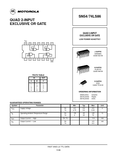
SN54/74LS86 QUAD 2-INPUT EXCLUSIVE OR GATE
QUAD 2-INPUT EXCLUSIVE OR GATE
LOW POWER SCHOTTKY
VCC 14 13 12 11 10 9 8
J SUFFIX CERAMIC CASE 632-08
GUARANTEED OPERATING RANGES
Symbol VCC TA IOH IOL Supply Voltage Operating Ambient Temperature Range Output Current — High Output Current — Low Parameter 54 74 54 74 54, 74 54 74 Min 4.5 4.75 – 55 0 Typ 5.0 5.0 25 25 Max 5.5 5.25 125 70 – 0.4 4.0 8.0 Unit V °C mA mA
FAST AND LS TTL DATA 5-89
14
1
2
3
4
6
7 GND
1
14
N SUFFIX PLASTIC CASE 646-06
1
TRUTH TABLE
IN A L L H H B L H L H OUT Z L H H L
14 1
D SUFFIX SOIC CASE 751A-02
ORDERING INFORMATION
SN54LSXXJ SN74LSXXN SN74LSXXD Ceramic Plastic SOIC
VCC = MAX, VIN = 2.7 V VCC = MAX, VIN = 7.0 V VCC = MAX, VIN = 0.4 V VCC = MAX VCC = MAX
N74F846N中文资料

元器件交易网DIP24:plastic dual in-line package; 24 leads (300 mil)SOT222-1SO24:plastic small outline package; 24 leads; body width 7.5 mm SOT137-1DefinitionsShort-form specification — The data in a short-form specification is extracted from a full data sheet with the same type number and title. For detailed information see the relevant data sheet or data handbook.Limiting values definition — Limiting values given are in accordance with the Absolute Maximum Rating System (IEC 134). Stress above one or more of the limiting values may cause permanent damage to the device. These are stress ratings only and operation of the device at these or at any other conditions above those given in the Characteristics sections of the specification is not implied. Exposure to limiting values for extended periods may affect device reliability.Application information — Applications that are described herein for any of these products are for illustrative purposes only. Philips Semiconductors make no representation or warranty that such applications will be suitable for the specified use without further testing or modification.DisclaimersLife support — These products are not designed for use in life support appliances, devices or systems where malfunction of these products can reasonably be expected to result in personal injury. Philips Semiconductors customers using or selling these products for use in such applications do so at their own risk and agree to fully indemnify Philips Semiconductors for any damages resulting from such application.Right to make changes — Philips Semiconductors reserves the right to make changes, without notice, in the products, including circuits, standard cells, and/or software, described or contained herein in order to improve design and/or performance. Philips Semiconductors assumes no responsibility or liability for the use of any of these products, conveys no license or title under any patent, copyright, or mask work right to these products, and makes no representations or warranties that these products are free from patent, copyright, or mask work right infringement, unless otherwise specified.Philips Semiconductors811 East Arques AvenueP.O. Box 3409Sunnyvale, California 94088–3409Telephone 800-234-7381© Copyright Philips Electronics North America Corporation 1999All rights reserved. Printed in U.S.A.Date of release: 06-99。
74系列中文资料(非常全)

74系列芯片资料反相器驱动器LS04 LS05 LS06 LS07 LS125 LS240 LS244 LS245与门与非门LS00 LS08 LS10 LS11 LS20 LS21 LS27 LS30 LS38或门或非门与或非门LS02 LS32 LS51 LS64 LS65异或门比较器LS86译码器LS138 LS139寄存器LS74 LS175 LS373反相器:Vcc 6A 6Y 5A 5Y 4A 4Y 六非门74LS04┌┴─┴─┴─┴─┴─┴─┴┐六非门(OC门) 74LS05 _ │14 13 12 11 10 9 8│六非门(OC高压输出) 74LS06 Y = A )││1 2 3 4 5 6 7│└┬─┬─┬─┬─┬─┬─┬┘1A 1Y 2A 2Y 3A 3Y GND驱动器:Vcc 6A 6Y 5A 5Y 4A 4Y┌┴─┴─┴─┴─┴─┴─┴┐│14 13 12 11 10 9 8│Y = A )│六驱动器(OC高压输出) 74LS07 │1 2 3 4 5 6 7│└┬─┬─┬─┬─┬─┬─┬┘1A 1Y 2A 2Y 3A 3Y GNDVcc -4C 4A 4Y -3C 3A 3Y┌┴─┴─┴─┴─┴─┴─┴┐_ │14 13 12 11 10 9 8│Y =A+C )│四总线三态门74LS125 │1 2 3 4 5 6 7│└┬─┬─┬─┬─┬─┬─┬┘-1C 1A 1Y -2C 2A 2Y GNDVcc -G B1 B2 B3 B4 B8 B6 B7 B8┌┴─┴─┴─┴─┴─┴─┴─┴─┴─┴┐8位总线驱动器74LS245 │20 19 18 17 16 15 14 13 12 11│)│DIR=1 A=>B│1 2 3 4 5 6 7 8 9 10│DIR=0 B=>A└┬─┬─┬─┬─┬─┬─┬─┬─┬─┬┘DIR A1 A2 A3 A4 A5 A6 A7 A8 GND正逻辑与门,与非门:Vcc 4B 4A 4Y 3B 3A 3Y┌┴─┴─┴─┴─┴─┴─┴┐│14 13 12 11 10 9 8│Y = AB )│2输入四正与门74LS08 │1 2 3 4 5 6 7│└┬─┬─┬─┬─┬─┬─┬┘1A 1B 1Y 2A 2B 2Y GNDVcc 4B 4A 4Y 3B 3A 3Y┌┴─┴─┴─┴─┴─┴─┴┐__ │14 13 12 11 10 9 8│Y = AB )│2输入四正与非门74LS00 │1 2 3 4 5 6 7│└┬─┬─┬─┬─┬─┬─┬┘1A 1B 1Y 2A 2B 2Y GNDVcc 1C 1Y 3C 3B 3A 3Y┌┴─┴─┴─┴─┴─┴─┴┐___ │14 13 12 11 10 9 8│Y = ABC )│3输入三正与非门74LS10 │1 2 3 4 5 6 7│└┬─┬─┬─┬─┬─┬─┬┘1A 1B 2A 2B 2C 2Y GNDVcc H G Y┌┴─┴─┴─┴─┴─┴─┴┐│14 13 12 11 10 9 8│)│8输入与非门74LS30│1 2 3 4 5 6 7│________└┬─┬─┬─┬─┬─┬─┬┘Y = ABCDEFGHA B C D E F GND正逻辑或门,或非门:Vcc 4B 4A 4Y 3B 3A 3Y┌┴─┴─┴─┴─┴─┴─┴┐2输入四或门74LS32│14 13 12 11 10 9 8│)│Y = A+B│1 2 3 4 5 6 7│└┬─┬─┬─┬─┬─┬─┬┘1A 1B 1Y 2A 2B 2Y GNDVcc 4Y 4B 4A 3Y 3B 3A┌┴─┴─┴─┴─┴─┴─┴┐2输入四或非门74LS02│14 13 12 11 10 9 8│___)│Y = A+B│1 2 3 4 5 6 7│└┬─┬─┬─┬─┬─┬─┬┘1Y 1A 1B 2Y 2A 2B GNDVcc 2Y 2B 2A 2D 2E 1F┌┴─┴─┴─┴─┴─┴─┴┐双与或非门74S51│14 13 12 11 10 9 8│_____)│2Y = AB+DE│1 2 3 4 5 6 7│_______└┬─┬─┬─┬─┬─┬─┬┘1Y = ABC+DEF1Y 1A 1B 1C 1D 1E GNDVcc D C B K J Y┌┴─┴─┴─┴─┴─┴─┴┐4-2-3-2与或非门74S64 74S65(OC门) │14 13 12 11 10 9 8│______________)│Y = ABCD+EF+GHI+JK│1 2 3 4 5 6 7│└┬─┬─┬─┬─┬─┬─┬┘A E F G H I GND页首非门,驱动器与门,与非门或门,或非门异或门,比较器译码器寄存器2输入四异或门74LS86Vcc 4B 4A 4Y 3Y 3B 3A┌┴─┴─┴─┴─┴─┴─┴┐│14 13 12 11 10 9 8│)│_ _│1 2 3 4 5 6 7│Y=AB+AB└┬─┬─┬─┬─┬─┬─┬┘1A 1B 1Y 2Y 2A 2B GND8*2输入比较器74LS688_Vcc Y B8 A8 B7 A7 B6 A6 B5 A5┌┴─┴─┴─┴─┴─┴─┴─┴─┴─┴┐8*2输入比较器74LS688│20 19 18 17 16 15 14 13 12 11│)││1 2 3 4 5 6 7 8 9 10│└┬─┬─┬─┬─┬─┬─┬─┬─┬─┬┘CE A1 B1 A2 B2 A3 B3 A4 B4 GND_Y=A1⊙B1+A2⊙B2+A3⊙B3+A4⊙B4+A5⊙B5+A6⊙B6+A7⊙B7+A8⊙B83-8译码器74LS138Vcc -Y0 -Y1 -Y2 -Y3 -Y4 -Y5 -Y6 __ _ _ _ __ _ _ __ _ _ __ _┌┴─┴─┴─┴─┴─┴─┴─┴┐Y0=A B C Y1=A B C Y2=A B C Y3=A B C│16 15 14 13 12 11 10 9 │)│__ _ _ __ _ __ _ __│1 2 3 4 5 6 7 8│Y4=A B C Y5=A B C Y6=A B C Y7=A B C└┬─┬─┬─┬─┬─┬─┬─┬┘A B C -CS0 -CS1 CS2 -Y7 GND双2-4译码器74LS139Vcc -2G 2A 2B -Y0 -Y1 -Y2 -Y3 __ __ __ __ __ __ __ __┌┴─┴─┴─┴─┴─┴─┴─┴┐Y0=2A 2B Y1=2A 2B Y2=2A 2B Y3=2A 2B│16 15 14 13 12 11 10 9 │)│__ __ __ __ __ __ __ __│ 1 2 3 4 5 6 7 8│Y0=1A 1B Y1=1A 1B Y2=1A 1B Y3=1A 1B└┬─┬─┬─┬─┬─┬─┬─┬┘-1G 1A 1B -Y0 -Y1 -Y2 -Y3 GND8*2输入比较器74LS688_Vcc Y B8 A8 B7 A7 B6 A6 B5 A5┌┴─┴─┴─┴─┴─┴─┴─┴─┴─┴┐8*2输入比较器74LS688 │20 19 18 17 16 15 14 13 12 11│)││1 2 3 4 5 6 7 8 9 10│└┬─┬─┬─┬─┬─┬─┬─┬─┬─┬┘CE A1 B1 A2 B2 A3 B3 A4 B4 GND_Y=A1⊙B1+A2⊙B2+A3⊙B3+A4⊙B4+A5⊙B5+A6⊙B6+A7⊙B7+A8⊙B8寄存器:Vcc 2CR 2D 2Ck 2St 2Q -2Q┌┴─┴─┴─┴─┴─┴─┴┐双D触发器74LS74│14 13 12 11 10 9 8 │)││1 2 3 4 5 6 7│└┬─┬─┬─┬─┬─┬─┬┘1Cr 1D 1Ck 1St 1Q -1Q GNDVcc 8Q 8D 7D 7Q 6Q 6D 5D 5Q ALE┌┴─┴─┴─┴─┴─┴─┴─┴─┴─┴┐8位锁存器74LS373│20 19 18 17 16 15 14 13 12 11│)││1 2 3 4 5 6 7 8 9 10│└┬─┬─┬─┬─┬─┬─┬─┬─┬─┬┘-OE 1Q 1D 2D 2Q 3Q 3D 4D 4Q GND--------------------------------------------------------------------------------常见数字逻辑器件中文注解74系列:74LS00 TTL 2输入端四与非门74LS01 TTL 集电极开路2输入端四与非门74LS02 TTL 2输入端四或非门74LS03 TTL 集电极开路2输入端四与非门74LS04 TTL 六反相器74LS05 TTL 集电极开路六反相器74LS06 TTL 集电极开路六反相高压驱动器74LS07 TTL 集电极开路六正相高压驱动器74LS08 TTL 2输入端四与门74LS09 TTL 集电极开路2输入端四与门74LS10 TTL 3输入端3与非门74LS107 TTL 带清除主从双J-K触发器74LS109 TTL 带预置清除正触发双J-K触发器74LS11 TTL 3输入端3与门74LS112 TTL 带预置清除负触发双J-K触发器74LS12 TTL 开路输出3输入端三与非门74LS121 TTL 单稳态多谐振荡器74LS122 TTL 可再触发单稳态多谐振荡器74LS123 TTL 双可再触发单稳态多谐振荡器74LS125 TTL 三态输出高有效四总线缓冲门74LS126 TTL 三态输出低有效四总线缓冲门74LS13 TTL 4输入端双与非施密特触发器74LS132 TTL 2输入端四与非施密特触发器74LS133 TTL 13输入端与非门74LS136 TTL 四异或门74LS138 TTL 3-8线译码器/复工器74LS139 TTL 双2-4线译码器/复工器74LS14 TTL 六反相施密特触发器74LS145 TTL BCD—十进制译码/驱动器74LS15 TTL 开路输出3输入端三与门74LS150 TTL 16选1数据选择/多路开关74LS151 TTL 8选1数据选择器74LS153 TTL 双4选1数据选择器74LS154 TTL 4线—16线译码器74LS155 TTL 图腾柱输出译码器/分配器74LS156 TTL 开路输出译码器/分配器74LS157 TTL 同相输出四2选1数据选择器74LS158 TTL 反相输出四2选1数据选择器74LS16 TTL 开路输出六反相缓冲/驱动器74LS160 TTL 可预置BCD异步清除计数器74LS161 TTL 可予制四位二进制异步清除计数器74LS162 TTL 可预置BCD同步清除计数器74LS163 TTL 可予制四位二进制同步清除计数器74LS164 TTL 八位串行入/并行输出移位寄存器74LS165 TTL 八位并行入/串行输出移位寄存器74LS166 TTL 八位并入/串出移位寄存器74LS169 TTL 二进制四位加/减同步计数器74LS17 TTL 开路输出六同相缓冲/驱动器74LS170 TTL 开路输出4×4寄存器堆74LS173 TTL 三态输出四位D型寄存器74LS174 TTL 带公共时钟和复位六D触发器74LS175 TTL 带公共时钟和复位四D触发器74LS180 TTL 9位奇数/偶数发生器/校验器74LS181 TTL 算术逻辑单元/函数发生器74LS185 TTL 二进制—BCD代码转换器74LS190 TTL BCD同步加/减计数器74LS191 TTL 二进制同步可逆计数器74LS192 TTL 可预置BCD双时钟可逆计数器74LS193 TTL 可预置四位二进制双时钟可逆计数器74LS194 TTL 四位双向通用移位寄存器74LS195 TTL 四位并行通道移位寄存器74LS196 TTL 十进制/二-十进制可预置计数锁存器74LS197 TTL 二进制可预置锁存器/计数器74LS20 TTL 4输入端双与非门74LS21 TTL 4输入端双与门74LS22 TTL 开路输出4输入端双与非门74LS221 TTL 双/单稳态多谐振荡器74LS240 TTL 八反相三态缓冲器/线驱动器74LS241 TTL 八同相三态缓冲器/线驱动器74LS243 TTL 四同相三态总线收发器74LS244 TTL 八同相三态缓冲器/线驱动器74LS245 TTL 八同相三态总线收发器74LS247 TTL BCD—7段15V输出译码/驱动器74LS248 TTL BCD—7段译码/升压输出驱动器74LS249 TTL BCD—7段译码/开路输出驱动器74LS251 TTL 三态输出8选1数据选择器/复工器74LS253 TTL 三态输出双4选1数据选择器/复工器74LS256 TTL 双四位可寻址锁存器74LS257 TTL 三态原码四2选1数据选择器/复工器74LS258 TTL 三态反码四2选1数据选择器/复工器74LS259 TTL 八位可寻址锁存器/3-8线译码器74LS26 TTL 2输入端高压接口四与非门74LS260 TTL 5输入端双或非门74LS266 TTL 2输入端四异或非门74LS27 TTL 3输入端三或非门74LS273 TTL 带公共时钟复位八D触发器74LS279 TTL 四图腾柱输出S-R锁存器74LS28 TTL 2输入端四或非门缓冲器74LS283 TTL 4位二进制全加器74LS290 TTL 二/五分频十进制计数器74LS293 TTL 二/八分频四位二进制计数器74LS295 TTL 四位双向通用移位寄存器74LS298 TTL 四2输入多路带存贮开关74LS299 TTL 三态输出八位通用移位寄存器74LS30 TTL 8输入端与非门74LS32 TTL 2输入端四或门74LS322 TTL 带符号扩展端八位移位寄存器74LS323 TTL 三态输出八位双向移位/存贮寄存器74LS33 TTL 开路输出2输入端四或非缓冲器74LS347 TTL BCD—7段译码器/驱动器74LS352 TTL 双4选1数据选择器/复工器74LS353 TTL 三态输出双4选1数据选择器/复工器74LS365 TTL 门使能输入三态输出六同相线驱动器74LS365 TTL 门使能输入三态输出六同相线驱动器74LS366 TTL 门使能输入三态输出六反相线驱动器74LS367 TTL 4/2线使能输入三态六同相线驱动器74LS368 TTL 4/2线使能输入三态六反相线驱动器74LS37 TTL 开路输出2输入端四与非缓冲器74LS373 TTL 三态同相八D锁存器74LS374 TTL 三态反相八D锁存器74LS375 TTL 4位双稳态锁存器74LS377 TTL 单边输出公共使能八D锁存器74LS378 TTL 单边输出公共使能六D锁存器74LS379 TTL 双边输出公共使能四D锁存器74LS38 TTL 开路输出2输入端四与非缓冲器74LS380 TTL 多功能八进制寄存器74LS39 TTL 开路输出2输入端四与非缓冲器74LS390 TTL 双十进制计数器74LS393 TTL 双四位二进制计数器74LS40 TTL 4输入端双与非缓冲器74LS42 TTL BCD—十进制代码转换器74LS352 TTL 双4选1数据选择器/复工器74LS353 TTL 三态输出双4选1数据选择器/复工器74LS365 TTL 门使能输入三态输出六同相线驱动器74LS366 TTL 门使能输入三态输出六反相线驱动器74LS367 TTL 4/2线使能输入三态六同相线驱动器74LS368 TTL 4/2线使能输入三态六反相线驱动器74LS37 TTL 开路输出2输入端四与非缓冲器74LS373 TTL 三态同相八D锁存器74LS374 TTL 三态反相八D锁存器74LS375 TTL 4位双稳态锁存器74LS377 TTL 单边输出公共使能八D锁存器74LS378 TTL 单边输出公共使能六D锁存器74LS379 TTL 双边输出公共使能四D锁存器74LS38 TTL 开路输出2输入端四与非缓冲器74LS380 TTL 多功能八进制寄存器74LS39 TTL 开路输出2输入端四与非缓冲器74LS390 TTL 双十进制计数器74LS393 TTL 双四位二进制计数器74LS40 TTL 4输入端双与非缓冲器74LS42 TTL BCD—十进制代码转换器74LS447 TTL BCD—7段译码器/驱动器74LS45 TTL BCD—十进制代码转换/驱动器74LS450 TTL 16:1多路转接复用器多工器74LS451 TTL 双8:1多路转接复用器多工器74LS453 TTL 四4:1多路转接复用器多工器74LS46 TTL BCD—7段低有效译码/驱动器74LS460 TTL 十位比较器74LS461 TTL 八进制计数器74LS465 TTL 三态同相2与使能端八总线缓冲器74LS466 TTL 三态反相2与使能八总线缓冲器74LS467 TTL 三态同相2使能端八总线缓冲器74LS468 TTL 三态反相2使能端八总线缓冲器74LS469 TTL 八位双向计数器74LS47 TTL BCD—7段高有效译码/驱动器74LS48 TTL BCD—7段译码器/内部上拉输出驱动74LS490 TTL 双十进制计数器74LS491 TTL 十位计数器74LS498 TTL 八进制移位寄存器74LS50 TTL 2-3/2-2输入端双与或非门74LS502 TTL 八位逐次逼近寄存器74LS503 TTL 八位逐次逼近寄存器74LS51 TTL 2-3/2-2输入端双与或非门74LS533 TTL 三态反相八D锁存器74LS534 TTL 三态反相八D锁存器74LS54 TTL 四路输入与或非门74LS540 TTL 八位三态反相输出总线缓冲器74LS55 TTL 4输入端二路输入与或非门74LS563 TTL 八位三态反相输出触发器74LS564 TTL 八位三态反相输出D触发器74LS573 TTL 八位三态输出触发器74LS574 TTL 八位三态输出D触发器74LS645 TTL 三态输出八同相总线传送接收器74LS670 TTL 三态输出4×4寄存器堆74LS73 TTL 带清除负触发双J-K触发器74LS74 TTL 带置位复位正触发双D触发器74LS76 TTL 带预置清除双J-K触发器74LS83 TTL 四位二进制快速进位全加器74LS85 TTL 四位数字比较器74LS86 TTL 2输入端四异或门74LS90 TTL 可二/五分频十进制计数器74LS93 TTL 可二/八分频二进制计数器74LS95 TTL 四位并行输入\\输出移位寄存器74LS97 TTL 6位同步二进制乘法器CD系列:CD4000 双3输入端或非门+单非门TICD4001 四2输入端或非门HIT/NSC/TI/GOLCD4002 双4输入端或非门NSCCD4006 18位串入/串出移位寄存器NSCCD4007 双互补对加反相器NSCCD4008 4位超前进位全加器NSCCD4009 六反相缓冲/变换器NSCCD4010 六同相缓冲/变换器NSCCD4011 四2输入端与非门HIT/TICD4012 双4输入端与非门NSCCD4013 双主-从D型触发器FSC/NSC/TOSCD4014 8位串入/并入-串出移位寄存器NSCCD4015 双4位串入/并出移位寄存器TICD4016 四传输门FSC/TICD4017 十进制计数/分配器FSC/TI/MOTCD4018 可预制1/N计数器NSC/MOTCD4019 四与或选择器PHICD4020 14级串行二进制计数/分频器FSCCD4021 08位串入/并入-串出移位寄存器PHI/NSCCD4022 八进制计数/分配器NSC/MOTCD4023 三3输入端与非门NSC/MOT/TICD4024 7级二进制串行计数/分频器NSC/MOT/TICD4025 三3输入端或非门NSC/MOT/TICD4026 十进制计数/7段译码器NSC/MOT/TICD4027 双J-K触发器NSC/MOT/TICD4028 BCD码十进制译码器NSC/MOT/TICD4029 可预置可逆计数器NSC/MOT/TICD4030 四异或门NSC/MOT/TI/GOLCD4031 64位串入/串出移位存储器NSC/MOT/TICD4032 三串行加法器NSC/TICD4033 十进制计数/7段译码器NSC/TICD4034 8位通用总线寄存器NSC/MOT/TICD4035 4位并入/串入-并出/串出移位寄存NSC/MOT/TI CD4038 三串行加法器NSC/TICD4040 12级二进制串行计数/分频器NSC/MOT/TICD4041 四同相/反相缓冲器NSC/MOT/TICD4042 四锁存D型触发器NSC/MOT/TICD4043 4三态R-S锁存触发器("1"触发) NSC/MOT/TI CD4044 四三态R-S锁存触发器("0"触发) NSC/MOT/TI CD4046 锁相环NSC/MOT/TI/PHICD4047 无稳态/单稳态多谐振荡器NSC/MOT/TICD4048 4输入端可扩展多功能门NSC/HIT/TICD4049 六反相缓冲/变换器NSC/HIT/TICD4050 六同相缓冲/变换器NSC/MOT/TICD4051 八选一模拟开关NSC/MOT/TICD4052 双4选1模拟开关NSC/MOT/TICD4053 三组二路模拟开关NSC/MOT/TICD4054 液晶显示驱动器NSC/HIT/TICD4055 BCD-7段译码/液晶驱动器NSC/HIT/TI CD4056 液晶显示驱动器NSC/HIT/TICD4059 “N”分频计数器NSC/TICD4060 14级二进制串行计数/分频器NSC/TI/MOT CD4063 四位数字比较器NSC/HIT/TICD4066 四传输门NSC/TI/MOTCD4067 16选1模拟开关NSC/TICD4068 八输入端与非门/与门NSC/HIT/TICD4069 六反相器NSC/HIT/TICD4070 四异或门NSC/HIT/TICD4071 四2输入端或门NSC/TICD4072 双4输入端或门NSC/TICD4073 三3输入端与门NSC/TICD4075 三3输入端或门NSC/TICD4076 四D寄存器CD4077 四2输入端异或非门HITCD4078 8输入端或非门/或门CD4081 四2输入端与门NSC/HIT/TICD4082 双4输入端与门NSC/HIT/TICD4085 双2路2输入端与或非门CD4086 四2输入端可扩展与或非门CD4089 二进制比例乘法器CD4093 四2输入端施密特触发器NSC/MOT/ST CD4094 8位移位存储总线寄存器NSC/TI/PHICD4095 3输入端J-K触发器CD4096 3输入端J-K触发器CD4097 双路八选一模拟开关CD4098 双单稳态触发器NSC/MOT/TICD4099 8位可寻址锁存器NSC/MOT/STCD40100 32位左/右移位寄存器CD40101 9位奇偶较验器CD40102 8位可预置同步BCD减法计数器CD40103 8位可预置同步二进制减法计数器CD40104 4位双向移位寄存器CD40105 先入先出FI-FD寄存器CD40106 六施密特触发器NSC\\TICD40107 双2输入端与非缓冲/驱动器HAR\\TI CD40108 4字×4位多通道寄存器CD40109 四低-高电平位移器CD40110 十进制加/减,计数,锁存,译码驱动STCD40147 10-4线编码器NSC\\MOTCD40160 可预置BCD加计数器NSC\\MOTCD40161 可预置4位二进制加计数器NSC\\MOTCD40162 BCD加法计数器NSC\\MOTCD40163 4位二进制同步计数器NSC\\MOTCD40174 六锁存D型触发器NSC\\TI\\MOTCD40175 四D型触发器NSC\\TI\\MOTCD40181 4位算术逻辑单元/函数发生器CD40182 超前位发生器CD40192 可预置BCD加/减计数器(双时钟) NSC\\TICD40193 可预置4位二进制加/减计数器NSC\\TICD40194 4位并入/串入-并出/串出移位寄存NSC\\MOTCD40195 4位并入/串入-并出/串出移位寄存NSC\\MOTCD40208 4×4多端口寄存器CD4501 4输入端双与门及2输入端或非门CD4502 可选通三态输出六反相/缓冲器CD4503 六同相三态缓冲器CD4504 六电压转换器CD4506 双二组2输入可扩展或非门CD4508 双4位锁存D型触发器CD4510 可预置BCD码加/减计数器CD4511 BCD锁存,7段译码,驱动器CD4512 八路数据选择器CD4513 BCD锁存,7段译码,驱动器(消隐)CD4514 4位锁存,4线-16线译码器CD4515 4位锁存,4线-16线译码器CD4516 可预置4位二进制加/减计数器CD4517 双64位静态移位寄存器CD4518 双BCD同步加计数器CD4519 四位与或选择器CD4520 双4位二进制同步加计数器CD4521 24级分频器CD4522 可预置BCD同步1/N计数器CD4526 可预置4位二进制同步1/N计数器CD4527 BCD比例乘法器CD4528 双单稳态触发器CD4529 双四路/单八路模拟开关CD4530 双5输入端优势逻辑门CD4531 12位奇偶校验器CD4532 8位优先编码器CD4536 可编程定时器CD4538 精密双单稳CD4539 双四路数据选择器CD4541 可编程序振荡/计时器CD4543 BCD七段锁存译码,驱动器CD4544 BCD七段锁存译码,驱动器CD4547 BCD七段译码/大电流驱动器CD4549 函数近似寄存器CD4551 四2通道模拟开关CD4553 三位BCD计数器CD4555 双二进制四选一译码器/分离器CD4556 双二进制四选一译码器/分离器CD4558 BCD八段译码器CD4560 "N"BCD加法器CD4561 "9"求补器CD4573 四可编程运算放大器CD4574 四可编程电压比较器CD4575 双可编程运放/比较器CD4583 双施密特触发器CD4584 六施密特触发器CD4585 4位数值比较器CD4599 8位可寻址锁存器。
74F74中文资料

TL F 946954F 74F74 Dual D-Type Positive Edge-Triggered Flip-FlopDecember1994 54F 74F74Dual D-Type Positive Edge-Triggered Flip-FlopGeneral DescriptionThe’F74is a dual D-type flip-flop with Direct Clear and Setinputs and complementary(Q Q)outputs Information at theinput is transferred to the outputs on the positive edge ofthe clock pulse Clock triggering occurs at a voltage level ofthe clock pulse and is not directly related to the transitiontime of the positive-going pulse After the Clock Pulse inputthreshold voltage has been passed the Data input is lockedout and information present will not be transferred to theoutputs until the next rising edge of the Clock Pulse inputAsynchronous InputsLOW input to S D sets Q to HIGH levelLOW input to C D sets Q to LOW levelClear and Set are independent of clockSimultaneous LOW on C D and S Dmakes both Q and Q HIGHFeaturesY Guaranteed4000V minimum ESD protection Commercial MilitaryPackagePackage DescriptionNumber74F74PC N14A14-Lead(0 300 Wide)Molded Dual-In-Line54F74DM(Note2)J14A14-Lead Ceramic Dual-In-Line74F74SC(Note1)M14A14-Lead(0 150 Wide)Molded Small Outline JEDEC74F74SJ(Note1)M14D14-Lead(0 300 Wide)Molded Small Outline EIAJ54F74FM(Note2)W14B14-Lead Cerpack54F74LM(Note2)E20A20-Lead Ceramic Leadless Chip Carrier Type C Note1 Devices also available in13 reel Use Suffix e SCXNote2 Military grade device with environmental and burn-in processing Use suffix e DMQB FMQB and LMQBLogic SymbolsTL F 9469–3TL F 9469–4IEEE IECTL F 9469–6TRI-STATE is a registered trademark of National Semiconductor CorporationC1995National Semiconductor Corporation RRD-B30M75 Printed in U S AConnection DiagramsPin Assignmentfor DIP SOIC and FlatpakTL F 9469–1Pin Assignmentfor LCCTL F 9469–2 Unit Loading Fan Out54F 74FPin Names Description U L Input IIH I ILHIGH LOW Output I OH I OLD1 D2Data Inputs1 0 1 020m A b0 6mACP1 CP2Clock Pulse Inputs(Active Rising Edge)1 0 1 020m A b0 6mAC D1 C D2Direct Clear Inputs(Active LOW)1 0 3 020m A b1 8mAS D1 S D2Direct Set Inputs(Active LOW)1 0 3 020m A b1 8mAQ1 Q1 Q2 Q2Outputs50 33 3b1mA 20mATruth TableInputs OutputsS D C D CP D Q QL H X X H LH L X X L HL L X X H HH H L h H LH H L l L HH H L X Q0Q0H(h)e HIGH Voltage LevelL(l)e LOW Voltage LevelX e ImmaterialQ0e Previous Q(Q)before LOW-to-HIGH Clock TransitionLower case letters indicate the state of the referenced input or output onesetup time prior to the LOW-to-HIGH clock transitionLogic DiagramTL F 9469–5 Please note that this diagram is provided only for the understanding of logic operations and should not be used to estimate propagation delays2Absolute Maximum Ratings(Note1)If Military Aerospace specified devices are required please contact the National Semiconductor Sales Office Distributors for availability and specifications Storage Temperature b65 C to a150 CAmbient Temperature under Bias b55 C to a125 CJunction Temperature under Bias b55 C to a175 C Plastic b55 C to a150 CV CC Pin Potential toGround Pin b0 5V to a7 0V Input Voltage(Note2)b0 5V to a7 0V Input Current(Note2)b30mA to a5 0mA Voltage Applied to Outputin HIGH State(with V CC e0V)Standard Output b0 5V to V CC TRI-STATE Output b0 5V to a5 5V Current Applied to Outputin LOW State(Max)twice the rated I OL(mA) ESD Last Passing Voltage(Min)4000V Note1 Absolute maximum ratings are values beyond which the device may be damaged or have its useful life impaired Functional operation under these conditions is not impliedNote2 Either voltage limit or current limit is sufficient to protect inputs Recommended Operating ConditionsFree Air Ambient TemperatureMilitary b55 C to a125 C Commercial0 C to a70 C Supply VoltageMilitary a4 5V to a5 5V Commercial a4 5V to a5 5VDC Electrical CharacteristicsSymbol Parameter54F 74FUnits V CC Conditions Min Typ MaxV IH Input HIGH Voltage2 0V Recognized as a HIGH Signal V IL Input LOW Voltage0 8V Recognized as a LOW Signal V CD Input Clamp Diode Voltage b1 2V Min I IN e b18mAV OH Output HIGH54F10%V CC2 5I OH e b1mA Voltage74F10%V CC2 5V Min I OH e b1mA74F5%V CC2 7I OH e b1mAV OL Output LOW54F10%V CC0 5V Min I OL e20mAVoltage74F10%V CC0 5I OL e20mAI IH Input HIGH54F20 0m A Max V IN e2 7V Current74F5 0I BVI Input HIGH Current54F100m A Max V IN e7 0V Breakdown Test74F7 0I CEX Output HIGH54F250m A Max V OUT e V CC Leakage Current74F50V ID Input Leakage74F4 75V0 0I ID e1 9m ATest All Other Pins GroundedI OD Output Leakage74F3 75m A0 0V IOD e150mVCircuit Current All Other Pins GroundedI IL Input LOW Current b0 6mA Max V IN e0 5V(D CP)b1 8V IN e0 5V(C D S D) I OS Output Short-Circuit Current b60b150mA Max V OUT e0VI CC Power Supply Current10 516 0mA Max3AC Electrical Characteristics74F54F74FT A e a25 CT A V CC e Mil T A V CC e Com Symbol Parameter V CC e a5 0VC L e50pF C L e50pF UnitsC L e50pFMin Typ Max Min Max Min Maxf max Maximum Clock Frequency10012580100MHzt PLH Propagation Delay3 85 36 83 88 53 87 8ns t PHL CP n to Q n or Q n4 46 28 04 410 54 49 2t PLH Propagation Delay3 24 66 13 28 03 27 1ns t PHL C Dn or S Dn to Q n or Q n3 57 09 03 511 53 510 5AC Operating Requirements74F54F74FSymbol ParameterT A e a25 CT A V CC e Mil T A V CC e Com Units V CC e a5 0VMin Max Min Max Min Maxt s(H)Setup Time HIGH or LOW2 03 02 0t s(L)D n to CP n3 04 03 0ns t h(H)Hold Time HIGH or LOW1 02 01 0t h(L)D n to CP n1 02 01 0t w(H)CP n Pulse Width4 04 04 0ns t w(L)HIGH or LOW5 06 05 0t w(L)C Dn or S Dn Pulse Width4 04 04 0nsLOWt rec Recovery Time2 03 02 0nsC Dn or S Dn to CP4Ordering InformationThe device number is used to form part of a simplified purchasing code where the package type and temperature range are defined as follows74F74S C XTemperature Range Family Special Variations74F e Commercial QB e Military grade device with54F e Military environmental and burn-inprocessingDevice Type X e Devices shipped in13 reelPackage Code Temperature RangeP e Plastic DIP C e Commercial(0 C to a70 C)D e Ceramic DIP M e Military(b55 C to a125 C)F e FlatpakL e Leadless Chip Carrier(LCC)S e Small Outline SOIC JEDECSJ e Small Outline SOIC EIAJPhysical Dimensions inches(millimeters)20-Lead Ceramic Leadless Chip Carrier(L)NS Package Number E20A5Physical Dimensions inches(millimeters)(Continued)14-Lead Ceramic Dual-In-Line Package(D)NS Package Number J14A14-Lead(0 150 Wide)Molded Small Outline JEDEC(S)NS Package Number M14A6Physical Dimensions inches(millimeters)(Continued)14-Lead(0 300 Wide)Molded Small Outline EIAJ(SJ)NS Package Number M14D14-Lead(0 300 Wide)Molded Dual-In-Line Package(P)NS Package Number N14A754F 74F 74D u a l D -T y p e P o s i t i v e E d g e -T r i g g e r e d F l i p -F l o pPhysical Dimensions inches (millimeters)(Continued)14-Lead Ceramic Flatpak (F)NS Package Number W14BLIFE SUPPORT POLICYNATIONAL’S PRODUCTS ARE NOT AUTHORIZED FOR USE AS CRITICAL COMPONENTS IN LIFE SUPPORT DEVICES OR SYSTEMS WITHOUT THE EXPRESS WRITTEN APPROVAL OF THE PRESIDENT OF NATIONAL SEMICONDUCTOR CORPORATION As used herein 1 Life support devices or systems are devices or 2 A critical component is any component of a life systems which (a)are intended for surgical implant support device or system whose failure to perform can into the body or (b)support or sustain life and whose be reasonably expected to cause the failure of the life failure to perform when properly used in accordance support device or system or to affect its safety or with instructions for use provided in the labeling can effectivenessbe reasonably expected to result in a significant injury to the userNational Semiconductor National Semiconductor National Semiconductor National Semiconductor National Semiconductores National Semiconductor CorporationGmbHJapan LtdHong Kong LtdDo Brazil Ltda(Australia)Pty Ltd 2900Semiconductor DriveLivry-Gargan-Str 10Sumitomo Chemical13th Floor Straight Block Rue Deputado Lacorda Franco Building 16。
SN74LS86中文资料

LOW POWER SCHOTTKYDevice Package Shipping SN74LS86N 14 Pin DIP 2000 Units/Box SN74LS86D14 PinSOIC D SUFFIX CASE 751A2500/T ape & ReelPLASTIC N SUFFIX CASE 646141141ON Semiconductor and are trademarks of Semiconductor Components Industries, LLC (SCILLC). SCILLC reserves the right to make changes without further notice to any products herein. SCILLC makes no warranty, representation or guarantee regarding the suitability of its products for any particular purpose, nor does SCILLC assume any liability arising out of the application or use of any product or circuit, and specifically disclaims any and all liability, including without limitation special, consequential or incidental damages. “Typical” parameters which may be provided in SCILLC data sheets and/or specifications can and do vary in different applications and actual performance may vary over time. All operating parameters, including “Typicals” must be validated for each customer application by customer’s technical experts. SCILLC does not convey any license under its patent rights nor the rights of others.SCILLC products are not designed, intended, or authorized for use as components in systems intended for surgical implant into the body, or other applications intended to support or sustain life, or for any other application in which the failure of the SCILLC product could create a situation where personal injury or death may occur. Should Buyer purchase or use SCILLC products for any such unintended or unauthorized application, Buyer shall indemnify and hold SCILLC and its officers, employees, subsidiaries, affiliates, and distributors harmless against all claims, costs, damages, and expenses, and reasonable attorney fees arising out of, directly or indirectly, any claim of personal injury or death associated with such unintended or unauthorized use, even if such claim alleges that SCILLC was negligent regarding the design or manufacture of the part. SCILLC is an Equal Opportunity/Affirmative Action Employer. PUBLICATION ORDERING INFORMATIONASIA/PACIFIC: LDC for ON Semiconductor – Asia SupportPhone:303–675–2121 (Tue–Fri 9:00am to 1:00pm, Hong Kong Time)Toll Free from Hong Kong 800–4422–3781Email: ONlit–asia@JAPAN: ON Semiconductor, Japan Customer Focus Center4–32–1 Nishi–Gotanda, Shinagawa–ku, Tokyo, Japan 141–8549Phone: 81–3–5487–8345Email: r14153@Fax Response Line:303–675–2167。
74ls86中文资料_数据手册_参数
Singapore 049318
Harbour City, Canton Road, Tsim Sha Tsui,
Tel: 535-2100
Kowloon, Hong Kong
Fax: 535-1533
Tel: <852> (2) 735 9218
Fax: <852> (2) 730 0281
Hitachi Asia Ltd.
Hitachi Europe GmbH Electronic components Group Dornacher Stra§e 3 D-85622 Feldkirchen, Munich Germany Tel: <49> (89) 9 9180-0 Fax: <49> (89) 9 29 30 00
DP-14 Conforms Conforms 0.97 g
10.06 10.5 Max
14
8
5.5
1
7
1.42 Max
0.10 ± 0.10
1.27
*0.42 ± 0.08 0.40 ± 0.06
0.15 0.12 M
*Dimension including the plating thickness Base material dimension
For further information write to:
SN74F86中文资料

元器件交易网IMPORTANT NOTICETexas Instruments and its subsidiaries (TI) reserve the right to make changes to their products or to discontinueany product or service without notice, and advise customers to obtain the latest version of relevant informationto verify, before placing orders, that information being relied on is current and complete. All products are soldsubject to the terms and conditions of sale supplied at the time of order acknowledgement, including thosepertaining to warranty, patent infringement, and limitation of liability.TI warrants performance of its semiconductor products to the specifications applicable at the time of sale inaccordance with TI’s standard warranty. Testing and other quality control techniques are utilized to the extentTI deems necessary to support this warranty. Specific testing of all parameters of each device is not necessarilyperformed, except those mandated by government requirements.CERTAIN APPLICATIONS USING SEMICONDUCTOR PRODUCTS MAY INVOLVE POTENTIAL RISKS OFDEATH, PERSONAL INJURY, OR SEVERE PROPERTY OR ENVIRONMENTAL DAMAGE (“CRITICALAPPLICATIONS”). TI SEMICONDUCTOR PRODUCTS ARE NOT DESIGNED, AUTHORIZED, ORWARRANTED TO BE SUITABLE FOR USE IN LIFE-SUPPORT DEVICES OR SYSTEMS OR OTHERCRITICAL APPLICATIONS. INCLUSION OF TI PRODUCTS IN SUCH APPLICATIONS IS UNDERSTOOD TOBE FULLY AT THE CUSTOMER’S RISK.In order to minimize risks associated with the customer’s applications, adequate design and operatingsafeguards must be provided by the customer to minimize inherent or procedural hazards.TI assumes no liability for applications assistance or customer product design. TI does not warrant or representthat any license, either express or implied, is granted under any patent right, copyright, mask work right, or otherintellectual property right of TI covering or relating to any combination, machine, or process in which suchsemiconductor products or services might be or are used. TI’s publication of information regarding any thirdparty’s products or services does not constitute TI’s approval, warranty or endorsement thereof.Copyright © 1998, Texas Instruments Incorporated。
74系列各个芯片详细介绍
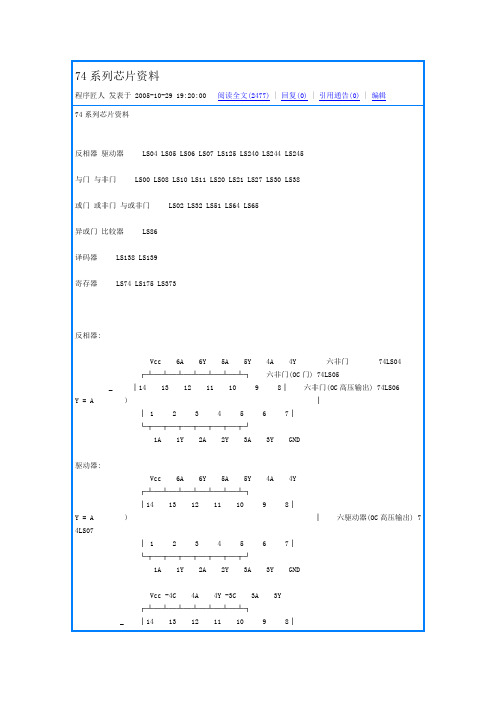
74系列芯片资料程序匠人发表于 2005-10-29 19:20:00 阅读全文(2477) | 回复(0) | 引用通告(0) | 编辑74系列芯片资料反相器驱动器 LS04 LS05 LS06 LS07 LS125 LS240 LS244 LS245与门与非门 LS00 LS08 LS10 LS11 LS20 LS21 LS27 LS30 LS38或门或非门与或非门 LS02 LS32 LS51 LS64 LS65异或门比较器 LS86译码器 LS138 LS139寄存器 LS74 LS175 LS373反相器:Vcc 6A 6Y 5A 5Y 4A 4Y 六非门 74LS04┌┴─┴─┴─┴─┴─┴─┴┐六非门(OC门) 74LS05_ │14 13 12 11 10 9 8│六非门(OC高压输出) 74LS06Y = A )││ 1 2 3 4 5 6 7│└┬─┬─┬─┬─┬─┬─┬┘1A 1Y 2A 2Y 3A 3Y GND驱动器:Vcc 6A 6Y 5A 5Y 4A 4Y┌┴─┴─┴─┴─┴─┴─┴┐│14 13 12 11 10 9 8│Y = A )│六驱动器(OC高压输出) 74LS07│ 1 2 3 4 5 6 7│└┬─┬─┬─┬─┬─┬─┬┘1A 1Y 2A 2Y 3A 3Y GNDVcc -4C 4A 4Y -3C 3A 3Y┌┴─┴─┴─┴─┴─┴─┴┐_ │14 13 12 11 10 9 8│Y =A+C )│四总线三态门 74LS125│ 1 2 3 4 5 6 7│└┬─┬─┬─┬─┬─┬─┬┘-1C 1A 1Y -2C 2A 2Y GNDVcc -G B1 B2 B3 B4 B8 B6 B7 B8┌┴─┴─┴─┴─┴─┴─┴─┴─┴─┴┐ 8位总线驱动器 74LS245 │20 19 18 17 16 15 14 13 12 11│)│ DIR=1 A=>B│ 1 2 3 4 5 6 7 8 9 10│ DIR=0 B=>A└┬─┬─┬─┬─┬─┬─┬─┬─┬─┬┘DIR A1 A2 A3 A4 A5 A6 A7 A8 GND页首非门,驱动器与门,与非门或门,或非门异或门,比较器译码器寄存器正逻辑与门,与非门:Vcc 4B 4A 4Y 3B 3A 3Y┌┴─┴─┴─┴─┴─┴─┴┐│14 13 12 11 10 9 8│Y = AB )│ 2输入四正与门 74LS08 │ 1 2 3 4 5 6 7│└┬─┬─┬─┬─┬─┬─┬┘1A 1B 1Y 2A 2B 2Y GNDVcc 4B 4A 4Y 3B 3A 3Y┌┴─┴─┴─┴─┴─┴─┴┐__ │14 13 12 11 10 9 8│Y = AB )│ 2输入四正与非门 74LS00 │ 1 2 3 4 5 6 7│└┬─┬─┬─┬─┬─┬─┬┘1A 1B 1Y 2A 2B 2Y GNDVcc 1C 1Y 3C 3B 3A 3Y┌┴─┴─┴─┴─┴─┴─┴┐___ │14 13 12 11 10 9 8│Y = ABC )│ 3输入三正与非门 74LS10 │ 1 2 3 4 5 6 7│└┬─┬─┬─┬─┬─┬─┬┘1A 1B 2A 2B 2C 2Y GNDVcc H G Y┌┴─┴─┴─┴─┴─┴─┴┐│14 13 12 11 10 9 8│)│ 8输入与非门 74LS30│ 1 2 3 4 5 6 7│ ________└┬─┬─┬─┬─┬─┬─┬┘ Y = ABCDEFGHA B C D E F GND页首非门,驱动器与门,与非门或门,或非门异或门,比较器译码器寄存器正逻辑或门,或非门:Vcc 4B 4A 4Y 3B 3A 3Y┌┴─┴─┴─┴─┴─┴─┴┐ 2输入四或门 74LS32│14 13 12 11 10 9 8│)│ Y = A+B│ 1 2 3 4 5 6 7│└┬─┬─┬─┬─┬─┬─┬┘1A 1B 1Y 2A 2B 2Y GNDVcc 4Y 4B 4A 3Y 3B 3A┌┴─┴─┴─┴─┴─┴─┴┐ 2输入四或非门 74LS02│14 13 12 11 10 9 8│ ___)│ Y = A+B│ 1 2 3 4 5 6 7│└┬─┬─┬─┬─┬─┬─┬┘1Y 1A 1B 2Y 2A 2B GNDVcc 2Y 2B 2A 2D 2E 1F┌┴─┴─┴─┴─┴─┴─┴┐双与或非门 74S51│14 13 12 11 10 9 8│ _____)│ 2Y = AB+DE│ 1 2 3 4 5 6 7│ _______└┬─┬─┬─┬─┬─┬─┬┘ 1Y = ABC+DEF1Y 1A 1B 1C 1D 1E GNDVcc D C B K J Y┌┴─┴─┴─┴─┴─┴─┴┐ 4-2-3-2与或非门 74S64 74S65(OC门) │14 13 12 11 10 9 8│ ______________)│ Y = ABCD+EF+GHI+JK│ 1 2 3 4 5 6 7│└┬─┬─┬─┬─┬─┬─┬┘A E F G H I GND页首非门,驱动器与门,与非门或门,或非门异或门,比较器译码器寄存器2输入四异或门 74LS86Vcc 4B 4A 4Y 3Y 3B 3A┌┴─┴─┴─┴─┴─┴─┴┐│14 13 12 11 10 9 8│)│ _ _│ 1 2 3 4 5 6 7│ Y=AB+AB└┬─┬─┬─┬─┬─┬─┬┘1A 1B 1Y 2Y 2A 2B GND8*2输入比较器 74LS688_Vcc Y B8 A8 B7 A7 B6 A6 B5 A5┌┴─┴─┴─┴─┴─┴─┴─┴─┴─┴┐ 8*2输入比较器 74LS688│20 19 18 17 16 15 14 13 12 11│)││ 1 2 3 4 5 6 7 8 9 10│└┬─┬─┬─┬─┬─┬─┬─┬─┬─┬┘CE A1 B1 A2 B2 A3 B3 A4 B4 GND_Y=A1⊙B1+A2⊙B2+A3⊙B3+A4⊙B4+A5⊙B5+A6⊙B6+A7⊙B7+A8⊙B8页首非门,驱动器与门,与非门或门,或非门异或门,比较器译码器寄存器3-8译码器 74LS138Vcc -Y0 -Y1 -Y2 -Y3 -Y4 -Y5 -Y6 __ _ _ _ __ _ _ __ _ _ __ _ ┌┴─┴─┴─┴─┴─┴─┴─┴┐ Y0=A B C Y1=A B B Y2=A B C Y3=A B C │16 15 14 13 12 11 10 9 │)│ __ _ _ __ _ __ _ __│ 1 2 3 4 5 6 7 8│ Y4=A B C Y5=A B C Y6=A B C Y7=A B C └┬─┬─┬─┬─┬─┬─┬─┬┘A B C -CS0 -CS1 CS2 -Y7 GND双2-4译码器 74LS139Vcc -2G 2A 2B -Y0 -Y1 -Y2 -Y3 __ __ __ __ __ __ __ __┌┴─┴─┴─┴─┴─┴─┴─┴┐ Y0=2A 2B Y1=2A 2B Y2=2A 2B Y3=2A 2B │16 15 14 13 12 11 10 9 │)│ __ __ __ __ __ __ __ __│ 1 2 3 4 5 6 7 8│ Y0=1A 1B Y1=1A 1B Y2=1A 1B Y3=1A 1B └┬─┬─┬─┬─┬─┬─┬─┬┘-1G 1A 1B -Y0 -Y1 -Y2 -Y3 GND8*2输入比较器 74LS688_Vcc Y B8 A8 B7 A7 B6 A6 B5 A5┌┴─┴─┴─┴─┴─┴─┴─┴─┴─┴┐ 8*2输入比较器 74LS688│20 19 18 17 16 15 14 13 12 11│)││ 1 2 3 4 5 6 7 8 9 10│└┬─┬─┬─┬─┬─┬─┬─┬─┬─┬┘CE A1 B1 A2 B2 A3 B3 A4 B4 GND_Y=A1⊙B1+A2⊙B2+A3⊙B3+A4⊙B4+A5⊙B5+A6⊙B6+A7⊙B7+A8⊙B8寄存器:Vcc 2CR 2D 2Ck 2St 2Q -2Q┌┴─┴─┴─┴─┴─┴─┴┐双D触发器 74LS74│14 13 12 11 10 9 8 │)││ 1 2 3 4 5 6 7│└┬─┬─┬─┬─┬─┬─┬┘1Cr 1D 1Ck 1St 1Q -1Q GNDVcc 8Q 8D 7D 7Q 6Q 6D 5D 5Q ALE┌┴─┴─┴─┴─┴─┴─┴─┴─┴─┴┐ 8位锁存器 74LS373│20 19 18 17 16 15 14 13 12 11│)││ 1 2 3 4 5 6 7 8 9 10│└┬─┬─┬─┬─┬─┬─┬─┬─┬─┬┘-OE 1Q 1D 2D 2Q 3Q 3D 4D 4Q GND型号器件名称厂牌[数据表]SN7400四2输入端与非门 TI[DATA]SN7401四2输入端与非门(OC) SN7402四2输入端或非门 TI[DATA]SN7403四2输入端与非门(OC)TI[DATA]SN7404六反相器 TI[DATA]SN7405六反相器(OC)TI[DATA]SN7406六高压输出反相器 (OC,30V)TI[DATA]SN7407六高压输出缓冲,驱动器(OC,30V)TI[DATA]SN7408四2输入端与门 TI[DATA]SN7409四2输入端与门(OC)TI[DATA]SN7410三3输入端与非门 TI[DATA]SN7412三3输入端与非门(OC)TI[DATA]SN7413双4输入端与非门 TI[DATA]SN7414六反相器TI[DATA]SN7416六高压输出反相缓冲/驱动器 I[DATA]SN7417六高压输出缓冲/驱动器(OC,15V)TI[DATA]SN7420双4输入端与非门 TI[DATA]SN7422双4输入端与非门(OC)TI[DATA]SN7423可扩展双4输入端或非门 TI[DATA]SN7425双4输入端或非门TI[DATA]SN7426四2输入端高压输出与非缓冲器 [DATA]SN7427三3输入端或非门TI[DATA]SN7428四2输入端或非缓冲器 I[DATA]SN74308输入端与非门TI[DATA]SN7432四2输入端或门。
- 1、下载文档前请自行甄别文档内容的完整性,平台不提供额外的编辑、内容补充、找答案等附加服务。
- 2、"仅部分预览"的文档,不可在线预览部分如存在完整性等问题,可反馈申请退款(可完整预览的文档不适用该条件!)。
- 3、如文档侵犯您的权益,请联系客服反馈,我们会尽快为您处理(人工客服工作时间:9:00-18:30)。
元器件交易网
DIP24:plastic dual in-line package; 24 leads (300 mil)SOT222-1
SO24:plastic small outline package; 24 leads; body width 7.5 mm SOT137-1
NOTES
Definitions
Short-form specification — The data in a short-form specification is extracted from a full data sheet with the same type number and title. For detailed information see the relevant data sheet or data handbook.
Limiting values definition — Limiting values given are in accordance with the Absolute Maximum Rating System (IEC 134). Stress above one or more of the limiting values may cause permanent damage to the device. These are stress ratings only and operation of the device at these or at any other conditions above those given in the Characteristics sections of the specification is not implied. Exposure to limiting values for extended periods may affect device reliability.
Application information — Applications that are described herein for any of these products are for illustrative purposes only. Philips Semiconductors make no representation or warranty that such applications will be suitable for the specified use without further testing or modification.
Disclaimers
Life support — These products are not designed for use in life support appliances, devices or systems where malfunction of these products can reasonably be expected to result in personal injury. Philips Semiconductors customers using or selling these products for use in such applications do so at their own risk and agree to fully indemnify Philips Semiconductors for any damages resulting from such application.
Right to make changes — Philips Semiconductors reserves the right to make changes, without notice, in the products, including circuits, standard cells, and/or software, described or contained herein in order to improve design and/or performance. Philips Semiconductors assumes no responsibility or liability for the use of any of these products, conveys no license or title under any patent, copyright, or mask work right to these products, and makes no representations or warranties that these products are free from patent, copyright, or mask work right infringement, unless otherwise specified.
Philips Semiconductors
811 East Arques Avenue
P.O. Box 3409
Sunnyvale, California 94088–3409
Telephone 800-234-7381
© Copyright Philips Electronics North America Corporation 2000
All rights reserved. Printed in U.S.A.
Date of release: 03-00。