ncpc2014slides
NCGuide教程及学习材料说明书
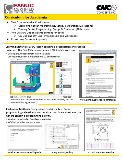
Presentations are viewable fromall electronic devices,and can be saved if using an IPad Learning Materials:Every lesson contains a presentation and reading materials.The first 13lessons contain NCGuide lab exercises.•On-line:Downloaded from lesson activities•Off-line:Included in a presentations CD and textbookCurriculum for AcademiaTwo Comprehensive CurriculumsMachining Center Programming,Setup,&Operation (24lessons)Turning Center Programming,Setup,&Operation (28lessons)Two Delivery Options (same content for both)On-Line and Off-Line (with manuals and workbooks)Proven Key Concepts ApproachView,print,&save reading materials Evaluation Methods:Every lesson contains a test.Some programming-related lessons contain a coordinate sheet exercise.Others contain a programming activity.•On-line:Downloaded from lesson activities•Off-line:Included in a workbookOn-line tests automatically graded Programming activity Coordinate sheet exerciseFor instructorsOn-going access to on-line contentAbility to monitor student progressInstructions for teaching/facilitating(manual)Lesson plans(manual)Excelgradebookincluded to recordgradesEasy access to NCGuide tutorialsTemplates provided for easy gradingTest results/recording responseCoordinate sheet exercises with answersProgramming activities with answersKey Concepts and LessonsMachining Center Programming,Setup,and Operation1:Know your machine-programmer's viewpoint1:Machine configurations1a:Certification cart2:CNC job work flow3:Visualizing the execution of a program4:Understanding the workpiece coordinate system5:Determining workpiece coordinate system offset values6:Setting workpiece coordinate system offsets7:Introduction to programming words2:You must prepare to write programs1:Preparation steps for programming3:Understand the motion types1:Motion commands4:Know the compensation types1:Introduction to compensation2:Tool length compensation3:Cutter radius compensation4:Workpiece coordinate system offsets5:You must provide structure to your CNC programs1:Introduction to program formatting2:Structured program format6:Special features that help with programming1:Hole-machining canned cycles2:Working with subprograms3:Other special programming features4:Programming rotary devices7:Know your machine-operator's viewpoint1:Tasks related to setup and running production2:Buttons and switches on the operation panels8:Know the three basic modes of operation1:The three modes of operation9:Understand the importance of procedures1:The key operation procedures10:You must know how to safely verify programs1:Program verificationOn-Line Learning Platform:Off-Line:Textbook,Workbook,Presentations CD: Comprehensive,yet tutorial:Questions about curriculum?Call847-639-8847or email***************44Little Cahill RoadCary,IL60013Ph:847-639-8847Email:***************Web:Students will spend about30hours working through each curriculum.。
Autodesk Navisworks 2014 Service Pack 1 用户指南说明书

Please send feedback on this guide to: **************************************Introduction (2)Installation (4)Uninstalling the Service Pack (4)Primary issues resolved by the Service Pack (5)1.Freedom (5)2.API / SDK (5)3.Core functionality (5)4.Interoperability (5)5.Clash Detective (5)6.Quantification (6)7.Autodesk ReCap (6)8.TimeLiner (6)10. Graphics (6)Thanks for downloading Autodesk® Navisworks® 2014 Service Pack 1. This document provides a quick summary of the new features and enhancements that are included in our Service Pack.Please remember to fully review the Installation Readme document before installing the Service Pack.We want to express our appreciation to all our customers who identified the issues we have addressed in this Service Pack release. Their reports gave us the opportunity to improve the product and to provide you with the best solution. We also thank you for your continued business, and for your feedback about this release.Many thanks,We strongly recommend that you read the Installation Readme document before you apply the Autodesk Navisworks Service Pack 1 to your productDuring installation, you may be prompted for the original installation media or a network image. In order to apply this Service Pack, you must have administrative privileges to install and uninstall products.After installing Autodesk Navisworks 2014 Service Pack 1, you must ensure that other users who share your Navisworks 2014 NWF files also install the same Service Pack. Failure to do so may mean that your Selection Set data becomes corrupted. This applies to Navisworks 2014 only. Navisworks 2014 NWF files shared with Navisworks 2013 and Navisworks 2012 users are not affectedOnce installed, Autodesk Navisworks 2014 Service Pack 1 cannot be uninstalled on its own. You must uninstall the complete product and then reinstall the original release of Autodesk Navisworks 2014 in order to revert to a non-Service Pack state. This applies to Navisworks 2014 only.Autodesk Navisworks Service Pack 1 provides the following fixes and enhancements:Added Autodesk ReCap support to Autodesk Freedom 2014Crash when opening a new model after using an incorrect SQL statement for an embeddeddatabase .Net APICrash caused by model refreshNWC files are created repeatedly when opening or appending native Revit models in NavisworksThe Memory Limit global option was using the wrong limit for any value greater than 4096MBPath matching fails if a new version of a file has had GUIDs added. Customers were reportingTimeLiner losing explicit selection between Navisworks 2014 and Navisworks 2014Cancelling model streaming could result in a situation where you could not subsequently open thesame fileSome properties could be reported incorrectly after appending models with different file units andsaving to NWDCrash when signing out of Autodesk 360Crash if Navisworks could not write information about the ribbon state due to user permissionsCrash when working with DWGs in Navisworks 2014. These issues were reported via theCustomer Error Reporting (CER) systemColours in some IFC models were being displayed differently in Autodesk Navisworks 2014 whencompared to other products providing IFC support. We have also added support for IFCmaterialsSwitchback to Inventor was not highlighting the appropriate selection when a composite groupnode was selected to switch back from in Autodesk Navisworks 2014.Added support for big endian JT files to Autodesk Navisworks Manage 2014 and AutodeskNavisworks Simulate 2014A number of issues around DGN native file readingIssue where Autodesk Navisworks 2014 NWC exporter from Revit was missing elements for wallsIssue where the Autodesk Navisworks 2014 NWC exporter from Revit would not export if youhave activated the View Template in the 3D viewIssue where clashing parametric primitives could give false negativesA number of issues around object identity, which means clash result status is preserved when areferenced model is updatedCrash in Autodesk Navisworks 2014 on Grouping Clash Results Containing Multiple ObjectsCrash when working with Clash Results. These issues were reported by customers via theCustomer Error Reporting (CER) systemCrash when loading a workspace while Clash Select tab is activeCrash when clicking on the title of grid column when trying to change clash statusIssue where Saving the Clash Viewpoint fails if user has not navigated in the modelIssue with auto-update on deleting a clash saved viewpoint will immediately generate a savedviewpoint for the default viewIssue where a message box stating "Redline requires a saved viewpoint..." if the Display Settings> Viewpoint > Manual is setIssue where using the Explode Group command in Clash results (when applied to multipleselection positions) results in all exploded items being collected together. We fixed this issue so that the exploded items are shown in the position of the group they belonged toIssue where the formula could not accept formula=if(true,,) and if(true,)Crash when choosing to Use New Master resourceA German Locale-specific issue where properties were not being mapped correctly afterperforming a Take OffIssue where the current selection was being reset to the first row each time a formula cell wasdeletedCrash when performing a Takeoff and running the command Delete Takeoff , if the user had usedthe column header to select allA number of positioning / rotation issues when opening Reality capture modelsAdded Autodesk ReCap support to Autodesk Navisworks Freedom 2014Issue where an un-mapped Display ID would map to the Start Date field automatically (CSV Link)Crash when clicking the cancel button on the 'working' dialog (when finding attached items inTimeLiner)Issue where pressing the Help button on the PMDB DS Login screen locks Autodesk Navisworks2014Crash when refreshing a linked schedule and then going to the Task paneIssue where overlay text won't be displayed in simulations when Autodesk Render is selected insimulation settingsFile locking issue where Asta projects could not be connected to in Autodesk Navisworks 2014 ifthey are open in Asta first.Issue when opening an Asta project in Autodesk Navisworks 2014 and then performing updatesin Asta would cause the synchronisation in Autodesk Navisworks 2014 to failCrash when selecting a steering wheel for navigationSignificant performance improvements when using Autodesk RenderingIssue where exporting a TimeLiner simulation using Autodesk Rendering results in an empty setof JPEGs.Issue where the pre-processing was hanging when exporting an image with Autodesk Renderingafter performing an interactive Ray Trace.A number of Ray Trace related crashes reported by customers via the Customer Error Reporting(CER) systemA number of lighting related crashes reported by customers via the Customer Error Reporting(CER) system.。
Presentation2014NXOpen-CaptureToCodeWithNXOpenJournaling-SUBMIT

Smarter decisions, better products.
NX Open Arபைடு நூலகம்hitecture
NX
Common API
Journaling
, C#, C++
Wide choice of languages (C++, Java, C#, ) Easy integration of recorded macros into programs Very complete coverage of NX Highly stable between releases Developed simultaneously with interactive functions Used internally by Siemens PLM (translators, auto-test)
NX Open Toolkits
Traditional Automation GUI Tools Knowledge-enabled Automation
Open C++
NX Open for .NET, Java Journaling Parasolid SNAP Block Styler
Simplified Tools
NX Open Features
Granularity
Curves Line Arc Conic Spline ….. Sheet & Solid bodies Cylinder Cone Body of revolution Ruled sheet Bounded plane Sheet through curve mesh B-surface Foreign surface Mass properties Interrogate topology Parasolid interface ….. Features All UG built-in features Datum planes and axes Relative positioning User-defined features Update ….. Sheet metal features Bends Forming tables Bend sequences Flat pattern
NHC课题 正式版

20
4.2
调试频率(次/天)
12月
4.2
20
GX160上 体
GX160下 体
GX160外 壳
GX160风 扇 罩
GX390风 扇 罩
铆 合 模 其 他
G4% X16O风冷
罩3%调试用时最
长 2% 1 . 0 4 % (450分) 0.39%
1%
(170分)
0%
3.18% (1380分)
0.14% (60分)
4 5 1025 84 68 29
98
28 19
4
1 9月
1 4 1400 98 28 19
290 102 38 6
260
95 52 21
365
8 75 4 44
10月
38 2578 2100
290 102
36
11月
52 3012 1980
260 95 21
12月
44 3120 1580
365 85 74
垫片厚度(mm)
项目 B1面
0.10mm OK
0.15mm OK
0.20mm OK
0.25mm 拉破
0.30mm 拉破
0.35Mpa 拉破
B2面
OK
OK
OK
OK
起皱
起皱
C面
起皱
起皱
起皱
OK
OK
OK
D面
OK
OK
OK
GX160上体 13%
GX160下体 0%
GX160风扇罩 47%
GX160外壳 5%
GX160风冷罩一次性不合格率统计
冲压系制品一次性不合格分类比例统计
Autodesk simulation cfd 2014安装说明

Autodesk simulation cfd 2014安装说明1、安装Autodesk 20142、使用这些系列号666-69696969、667-98989898、400-45454545、066-66666666等等以及其它你能找到的能用的系列号。
3、产品密码为809F1Autodesk simulation CFD 2014系列产品注册码如下:809F1 Autodesk Simulation CFD 2014810F1 Autodesk Simulation CFD Advanced 2014811F1 Autodesk Simulation CFD Motion 2014812F1 Autodesk Simulation CFD Design Study Environment 2014815F1 Autodesk Simulation CFD Connection for NX 2014819F1 Autodesk Simulation CFD Connection for ACIS 2014822F1 Autodesk Simulation CFD Connection for Pro/ENGINEER 2014824F1 Autodesk Simulation CFD Connection for Parasolid 20144、安装完成后,重启Autodesk产品5、在激活前,需要这样做:(二选一)-断开网络(可以拔出网线或用防火墙断开),这一步只是为了避免在线检查。
这时会告诉你需要联网,点击关闭并重新点击激活。
-点击激活,此时会在线检查,立即点击关闭,并重新点击激活。
6、选择“我已经从Autodesk取得激活码”。
7、在激活的界面上,启动XFORCE Keygen 32bits 或64bits 版本。
8、点击注册机界面上的Patch(即破解),此时会看到successfully patched(成功破解)。
《中文版SolidWorks-2014案例教程》很好PPT课件

下图所示轴承座零件就是由拉伸特征、筋特征和孔特征经过叠加、切割而形成的。
轴承座及其各组成特征
② 继续创建拉伸特征
④ 创建孔特征
③ 创建筋特征
① 创建拉伸特征的创建顺序,SolidWorks 2014将构成零件的特征分为基础特征和附 加特征两类。最先建立的特征为基础特征,它通常是零件最重要的特征。在建立好
8
过渡页
TRANSITION PAGE
9
3.2 拉伸特征
拉伸特征是创建三维模型时最常用的一种基础特征,它通过将截面草图沿 指定方向拉伸一定距离而得到。SolidWorks中的拉伸特征包括拉伸凸台/基体 和拉伸切除两种。
10
3.2 拉伸特征
拉伸凸台/基体是指按照给定数值将一个截面草图沿指定方向拉伸一段距
完全贯穿
从截面草图的草绘平面处开始拉伸,直到贯穿几何体的所有部 分,如18页图(a)所示
成形到一顶点 成形到一面
拉伸到所选顶点所在的平面或基准面处,如18页图(b)所示 拉伸到所选的平面、曲面或基准面处,如18页图(c)所示
到离指定面指定的 距离
拉伸到距离指定面一定距离的位置,如18页图(d)所示
成形到实体 两侧对称
中文版
SolidWorks 2014
案例教程
中文版SolidWorks2014
2
目录 CONTENTS
01 特征建模概述
04 扫描特征
02 拉伸特征
05 放样特征
03 旋转特征
06 编辑特征参数
3
过渡页
TRANSITION PAGE
4
3.1 特征建模概述
Navisworks 2014及更新版本对点云数据的增强功能分析说明书

CL10684Navisworks has a Point to Prove, But What is the Point?Ian PhilpottJ Murphy and SonsLearning Objectives• Use Recap to extract the required data from the point cloud and import in to Navisworks • Use Navisworks to manually verify headroom clearance from a road alignment to a point cloud ofan existing structure • Use clearance envelopes with Navisworks Clash Detective to automate structure clearance checks • Using Navisworks to visualise complex projects and demonstrate visibility requirements toapproving authoritiesDescriptionNavisworks 2014 onwards gained an enhanced capability to utilise point cloud data via the use of the Recap engine. The aim of this class is to demonstrate how this enhanced capability can be used on infrastructure projects with point clouds upwards of 2.5billion points. As Infrastructure Engineers we often have to work around existing constraints of buildings, footbridges, flyovers, railway arches, bridges and a wide range of other structures, all of which need clearances from our carriageway envelopes. We will look at how these large point clouds can be used to not only demonstrate these interactions to our clients and stakeholders but also how to utilise the model to check lateral and headroom clearances and visually inspect visibility issues.Your AU ExpertsIan has recently joined J Murphy and Sons as a Civil BIM Lead after 14 years at Aecom (formerly Scott Wilson / URS). Ian’s role is to develop the Civil BIM capabilities, both in terms of technology and process across Civil, Water, Power and Rail sectors. He specializes in 3D modelling and coordination of complex infrastructure projects and championing the use of 3D modelling and Building Information Modelling (BIM) across teams in multiple offices. Ian also has experience of leading discipline steering groups,standards development and template/workflow creation for the use of AutoCAD Civil 3D, Infraworks and Navisworks. Ian has extensive project experience in the design, 3D modelling and model co-ordination on major urban regeneration and development projects across many disciplines including highways,infrastructure, drainage, utilities, and external building interfaces using AutoCAD Civil 3D and Navisworks software.IntroductionAn enormous part of civil engineering projects is interface management, whether that is interfaces between new permanent works and existing features or clearances to enable construction to be undertaken safely and effectively.Point cloud capture technology now enables these features to be surveyed in unprecedented detail. But there is no point in capturing detail if you aren’t going to utilise the data in a meaningful and productive manner.Data PreparationA proper process of data management is essential in a BIM project workflow. This process starts withyour existing site data and at the beginning of the project. Failure to manage your data effectively willadd further complexity as the project progresses and is much harder to correct later than if donecorrectly at the beginning.Point Cloud Clean UpDepending on when and how the point cloud data was captured will determine how much clean-up is required. As an example a point cloud of a highway will need more cleaning up than a rail survey. Iwould recommend that the survey specification includes cleaning up the data as this is best carried outby the survey team as the software provided with the scanners has specialist tools for this process. Summarised below are the key points in cleaning up your point cloud data in both Recap and Civil3D.•Noise removal – Utilising Recap any area of noise can be identified.Noise caused byvehicle passingthrough duringscanningTo create Civil3D surfaceIn order to create a surface from the point cloud data it is necessary to transfer the data from Recap to Civil3D. There are two main ways this can be accomplished.• Option 1 – Export / ImportIn earlier versions of Civil3D it wasn’t possible to create surfaces directly from the Recap files. To overcome this, the recap file can be exported as a .pts file. From the home tab in Recap select the highlighted iconto export the project. Use Limit Box to isolate area of noise so they can be erased without affecting points to be retained Noise can bedeleted by window select and pressing deleteIn Civil3D, start a new drawing in yourCivil3D template. Go to the Prospector tab and right click on Point CloudsGive the point cloud a name and choose thedisplay styleChoose the importformat, .pts in thiscase and use the +icon to open thedialogue to select thefile to import•Option 2 – Direct Reference and Surface Creation – In Civil3D 2015 a subscription extension was release to allow the creation of surfaces directly from Recap point clouds. In Civil3D 2016 a “Create Surfaces from Point Cloud” can be found on the “Home” tab in the “Surfaces” drop down. From there on the process is the same.Attach the Recap filefrom the referencemanagerAlternatively via the “Attach” command in “Point Cloud” section in the “Insert” tabSelect “Create Surface from PointCloud”Select the point cloudthen go back to the“General” tab andgive the point cloud aname. In the “Non-Ground PointFiltering” tab choosethe filtering method.I find KringingInterpolation themost effective forremoving vegetationand vehicles. Click“Create Surface” andCivil3D will work inthe background tocreate a surface thepoint cloudSurface SimplificationEven after some filtering at import and applying a boundary, so only the carriageway remains, the number of points is still excessive (>2.6million). This has a major impact on Civil3D performance for little or no gain in level accuracy. The number of points can be reduced further and Civil3D performance increased by using surface simplification just like any other Civil3D surfaces.Select our surface and fromthe “Surface Edit” menuselect Simplify SurfaceAdjust the percentage of points and maximum change in elevation. This will depend on the density of the point cloud and what has been surveyed. For example a survey of earthworks in an open field the maximum elevation change could be increased to 0.2m or greater. But for road pavement tie-ins a tighter tolerance is neededThe filtering has removed 1.5M points from the surface but still maintained the accuracy to plus/minus10mm from the original dataImport Point Cloud NavisworksThe point cloud data can be directly appended in to the Navisworks model and even with large data sets the navigation is smooth. However, some regeneration lag is obvious as the point cloud data loads when you move to an area outside the previous display envelope. It is recommended that point cloud model are broken up in to manageable segments that can then be switched on/off inside Navisworks asneeded but can all be switched on when required for presentations.Preparing Your Civil3D Model for NavisworksHow you prepare the Civil3D model for Navisworks will depend on the current design stage and whether you want the information to speed up the design process or to present in the information more formally. Summarised below are the workflows for each:-•Design Workflow – The aim of this is to provide quick transfer of data between Civil3D and Navisworks for use as design verification.o Set corridor surface to triangulation.o Create a Layer State with only your main surface layer and surface triangles layer switched on.o Export surface to a .nwc file (NWCOUT). This is not as quick as direct import of .dwg in to Navisworks but gives more reliable results.•Presentation Workflow – The aim of this is to get better quality data in to Navisworks for a more professional output at presentation stages.o Select corridor.o From the ribbon select “Extract Corridor Solids”.o Add Baseline Regions and adjust any settings.o Click Create Solids.o Create a new layer state where only the solid are shown then export to a .nwc.Which one do you use? The design workflow is just that, it gets you the answers you need in terms of being able to see your design and measure from it. The presentation workflow gives you the ability to colourise not only the surface but also the kerb, earthworks and pavement construction. Much more visual control for presentation and when sectioning through the data.The Manual WorkflowThe manual workflow is a very simple process of using Navisworks to check the clearance. Why would you do this in Navisworks and not just within your design software such as Civil3D I here you ask? Well, there are some advantages / disadvantages but it is all about having tools in your toolbox so that you can use the right method for each situation as it presents itself on a project.•Advantageso A more visual process inside Navisworks than within Civil3D.o Results can easily be saved as picture which can be incorporated in to a design verification report.o Viewpoints can be saved to you can easily return to ensure the results remain valid as designs evolve and change.•Disadvantageso Additional process.Manual Headroom ChecksNow we have done all that data preparation we can check some headrooms. This manual process can be used at any time, particularly useful if you only have a simple case or a single clearance to check. I like to use it during my design process just to make sure the headroom is about right, small adjustments can then be made later based on other influencing factors. Manual headroom checks are so easy.Pan and rotate your model until the two elements to be measured between are visible.On the “Review” tab drop open the “Measure”command and select “Pointto Point”.Again on the “Review” tab open the “Lock” menu and select “Z Axis”. This ensures a true vertical headroommeasurement is taken.Now select a point on the underside of the bridge and on the road (Note icon changes depending on whether you are selecting a point or a face). Converting to a Redline automatically creates a saved view of that dimension which can be renamed in the SaveViewpoints window.Adding Some Little HelpersFinding it hard to locate where you want to measure to or from using this manual method? Why not leave yourself some little helpful markers. Place some Civil3D COGO points or a feature line on the surface where you want to measure up from. Don’t forget to adjust your Navisworks export layer state so they are visible in the export.The Intermediate WorkflowThe intermediate workflow gives the ability to use Navisworks Clash Detective without the complexity of working with Subassembly Composer. On the downside without using Subassembly Composer some versatility in customising the shape of the clearance envelope is lost. This workflow also only became possible with the addition of the “Extract Surface as a Solid” command in Civil3D 2015 Productivity Pack 1 and onwards. So, what is the workflow?Create a new assembly, using generic links to represent the top and width of theclearance envelope. Use a “Link Vertical” subassembly to set the height of the clearance envelope. This allows the alignment and profile created for the main road ensuring that clearance height is dynamic to the road surface. Don’t forget to omit the link on the vertical leg.Create a corridor based on the new clearance assembly and extend the corridor over the region where the clearance check is to be performed. Now create a surface for this clearancecorridor.Select the surface and from the “Extract from Surface” drop down select “Extract Solids from Surface”.Enter the depth of solid to extract. This should be the same as the height of the vertical link in the corridor subassembly. Don’t forget this need a MINUS sign or the solid will be from the surface upwards. Now set the layer state to show this and export to a Navisworks file.Append the clearance solid model to the Navisworksmodel.Right click on the clearance model in the “Selection Tree” and under “Override Item” the colour and transparency can be adjusted. It can be clearly seen in this view that the clearance envelope impinges on the bridge. Open Clash Detective, create a new clash test and give it a name. Select the components to be clash tested. For this test the type of test needs to be set to “Clearance” the tolerance to “0.001m” and “Points” select for the point cloud model.Now run the test.identified but this is only asgood as how the data is setupin the first place. It is obviousin this example where theclash is but it doesn’taccurately pinpoint theproblem. If the problem areahad been less obvious e.g. adrainage pipe from the deckabove this method will havestill flagged an issue sofurther investigation could beundertaken.The Advanced WorkflowThe advanced workflow utilises subassembly composer to create a bespoke subassembly to representthe clearance envelope. The advantage of this workflow is that it can be customised to work in multiplesituations. For example, additional links could be added to model structure free zones. The principlecould also be adapted to create clearance envelopes of a wide variety of shapes and sizes that couldn’tbe easily supported by the intermediate workflow. The disadvantage is that a degree of skill in the useof subassembly is required, although a valuable software add-on, not a commonly used one. Subassembly CreationThis section describes how Subassembly Composer can be used to create a subassembly that forms aclearance envelope that can be used to perform the clearance clash check with. These principles couldbe applied to a multitude of situations and these are generally only limited by what can be imagined orthe skill level to make Subassembly Composer / Civil3D do what is required. The first stage is to create asketch of the subassembly to be created.Sketch the subassembly and annotate with the required points links and parameter to be incorporated.Open Subassembly Composer and got to the “Input/Output Parameter” tab. The follow parameters are needed. - Width left & right of the alignment.- Headroom could be 1 value or 2 as here. -Sag Correction which is important for road design.Now “Target Parameters” -TAR_EX_ROAD is crucial this will make links L1 & L2 follow the surface of the road.-CH_LEFT & RIGHT allow the width of L1 and L2 to be overridden bytargeting alignments / features lines or polylinesin the design.Links L1 & L2 are “Surface Links” meaning correctly targeted they will follow a Civil3D surface. The Input Parameters and Target Parameters previously set upare used on control variousfunctions (as highlighted).Points P5 & P6 are insertedwith the associated links. TheY axis dimension is controlledusing an equation ofparameters created above.Corridor ConstructionBefore the subassembly can be used to create a corridor, it has to be imported in to Civil3D. This can be done from the “Import Subassemblies” command on the “Insert” tab of the main ribbon. A corridor can then be created in the same manner as the intermediate option but instead of creating surface solids a set of corridor solids will be created. This can be done by selecting the corridor and selecting the “Extract Corridor Solids” from the ribbon.Export to NavisworksAgain, this follows a very similar process to the intermediate process.Navisworks Clash DetectionWe have already shown that Clash Detective is a very powerful analytical tool inside Navisworks. If your modelling process is correctly set-up then the headroom check can not only become automated in to your review process but can also be reused on project after project. In order to maximise the benefit of this workflow, there are a number of points that need to be considered.• A consistent naming protocol must be used to name the clearance envelope objects. This enable a Search Set to be created within Navisworks to automatically select these clearanceenvelopes which can then be clash checked against the point cloud.•Save this search Search Set so it can be reused on the next project, providing the same objectnaming convention is used.•This process would then enable any number of clearance envelopes to be checked in a single process AND repeated at any time as the design evolves without significant rework.•Using the Clash Detective also automates the compliance reporting of these clearance checks. The process for creating and running these tests in Clash Detective are, again, as shown for the intermediate process.Clash Detective 2.0Both the intermediate and advanced workflows do a great job in automating the workflow of checking clearance envelopes but the results from clash checking against a point cloud don’t easily hone in on the clashing area only that one exists. How can this be improved?•What can we do now?o Extract the element to be checked against from the bulk point cloud and save it as a different file thus only checking the clearance object against the actual object to bechecks.o Take that a step further for complex project and split the object down further in to say deck and piers.o Understand if this process is going to be needed when specifying your point cloud survey. Tell your survey team so they can help with the tasks above at time of captureand post processing.•What can future software do?o Object recognition, turn the point cloud in to model objects.o Highlight points within the point cloud that are affected.VisualisationVisualisation is becoming an increasingly important part of civil engineering projects. It can be used as part of the design process, stakeholder management and approval process. In 2014 Navisworks gained the ability to handle point cloud data via the Recap engine which significantly enhanced the capability by allowing existing site features to be quickly and accurately represented in our models.VisibilityWhen working on highways and rail projects visibility to particular features such as signals and signs are critical. The minimum distances at which these features are visible is governed by design rules and have to be checked and verified during the design process.There is no specific functionality within Navisworks to perform these visibility checks but these check can be easily achieved with a manual process and stored for future reference. The workflow is as follows:-•Process the point cloud data in Recap.•Model your highway / railway (or whatever) in Civil3D.•Place the entity to checked for visibility e.g. traffic sign within the Civil3D model.•Place a marker in the Civil3D model at the observation location.•Set the layerstate in Civil3D to “Navis Export” (see above) and export the Civil3D model.•Create a new Navisworks model and append both the Recap data and the Civil3D data.•Navigate to the observation location within Navisworks and save the viewpoint.• If the object to be observed isn’t visible navigate to a position where it is visible and place a tag.This saves a viewpoint and enables a comment to be saved. The distance can then be measured to the object using the measure tools. Although this might seem like a primitive workflow in practice it’s very effective as it not only considers the horizontal plane but also the vertical plane. Furthermore, the impact of other features such as lighting columns and tree canopies that are hard to assess on 2D plans are also assessed easily. Not to forget a picture says a thousand words.What Else Can I Do?We have looked at clearance check and visibility, but what else can be done utilising the power of Navisworks with point clouds?• Complex interface assessments`FIGURE 1 - INTERFACE ASSESSMENT EXAMPLE • Temporary works assessments.• Traffic management space planning.SummaryTo summarise, the use of Recap, Civil3D, Subassembly Composer and Navisworks can enhance the design process by enabling the utilisation detailed point cloud data to be used to clash check and visualise the complex interfaces of Civil Engineering projects. Looking at the objectives you should now be able to do the following:-• Use Recap to manipulate the point cloud data to make is manageable when importing it in toCivil3D and use Civil3D to refine the point cloud information in to intelligent but manageable surfaces.• Combine the point cloud data and Civil3D data in Navisworks and use Navisworks tools toquickly check headroom.Interface with existing brick arch bridge. Unsurveyed at time of design due to access restrictions.Determine height of cut off wall, again in an area unsurveyed due to access restrictions.•Use two methods to create clearance envelopes in Civil3D and then use Navisworks Clash Detective to automate the clash checking process, checking a the full envelope rather than just a few point locations.•Use Navisworks to visualise aspects of your project and demonstrate to approving authorities that issues such as clearance and visibility have been considered.。
as-2014使用说明

PKPM计算结果数值处理程序-2014使用说明李平昌中国建筑西南设计研究院有限公司一、简介PKPM计算结果数值处理程序是基于cad平台的Vlisp命令程序,对板、筏板和梁、柱、墙的pkpm计算结果进行过滤、归并和比较等数据处理,提取结构设计需要的信息,以提高设计工作效率。
二、使用限制本程序仅针对(由pkpm的结果T文件转成的)cad图形中的文本进行数据分析和处理,不涉及内力、材料、抗震等级等其它结构信息。
使用程序时,过滤、归并和比较的范围及控制参数,应由设计人员和专业负责人按结构合理、经济节约的要求设定,程序的相关控制参数默认值仅供参考。
用户必须清楚在程序的准确性或可靠性上,开发者未作任何直接或暗示性的担保,使用者在运用命令前应注意存盘,并应对程序生成的结果进行独立的核查。
三、启动方法启动autocad后,通过菜单:工具→加载应用程序;或直接在命令行中,输入appload命令调用as-2014.vlx。
程序加载后,在cad命令行中键入as命令,启动程序对话框,用户操作程序成功运行后,将在命令行中显示:“处理成功,感谢您的使用!”并给出其它必要的提示信息。
四、具体功能介绍1、主菜单启动命令为as。
主菜单中,列出了各个功能模块。
点选每个模块时,在下方将显示对该模块功能的简单介绍。
选定所需的功能模块后,点击运行按钮,执行该模块。
在每个模块名称后面的括号中,给出了调用该模块的快捷命令。
2、楼板配筋过滤及自动选筋①主要功能是滤除不大于所设置过滤上限的楼板配筋值,即剩下的数值均大于过滤上限。
②板实配有通长钢筋时,过滤上限可填通长筋面积;否则可填板配筋施工图中未原位注明(在板配筋说明中统一注写)的最小规格板筋的面积。
③板面配筋和板底配筋可有不同的过滤上限。
④实配无通长筋时,则自动选配全配钢筋,其面积≥楼板计算配筋值。
⑤若通长钢筋面积=过滤上限,则自动选配的附加钢筋和通长钢筋面积之和满足计算要求:附加钢筋面积+过滤上限≥楼板配筋计算值。
- 1、下载文档前请自行甄别文档内容的完整性,平台不提供额外的编辑、内容补充、找答案等附加服务。
- 2、"仅部分预览"的文档,不可在线预览部分如存在完整性等问题,可反馈申请退款(可完整预览的文档不适用该条件!)。
- 3、如文档侵犯您的权益,请联系客服反馈,我们会尽快为您处理(人工客服工作时间:9:00-18:30)。
D – Dice Game
Problem Two players have two dice each. The player who throws bigger sum wins. Who has higher chances of winning? Solution For each player, calculate the probability distribution of his/her throws (calculate the probability of each possible outcome). Using this information, determine the probability of winning for both players. Shorter solution Insight: both distributions are symmetric around the mean. Therefore it’s enough to compare the expected values of both probability distributions – compare the sum of both lines of input.
Problem Author: Markus S. Dregi, Pål G. Drange NCPC 2014 solutions
C – Catalan Square
Problem Calculate Sn = number.
n k =0 Ck Cn−k ,
where Cn is the nth Catalan
Problem Author: Markus S. Dregi, Pål G. Drange NCPC 2014 solutions
Solution Branching on putting either v or one of its neighbors in the solution yields a 5k · n time algorithm. Too slow. (Unless clever heuristics) After picking the first vertex, there is always a vertex of degree at most 3. Branching on the lowest degree vertex yields 4k n time provided that connected components are solved separately. Can get accepted, depending on implementation. Branching on picking either v or pairs of neighbors yields a 3k · n time algorithm, due to the recurrence T (k ) = T (k − 1) + 6T (k − 2). Accepted. Combining the two algorithms, solving components independently, branching on lowest degree vertex and trying pairs of neighbors, gives the recurrence T (k ) = T (k − 1) + 3T (k − 2) yielding a 2.31k · n time algorithm. Even more accepted.
Suggested solutions
1
Look at the given formula for Cn and figure out that Cn satisfies the recurrence C0 = 1 and Cn+1 = n k =0 Ck · Cn−k , which means that the numbers Sn are just the Catalan numbers shifted one place to the right. Calculate Sn for some values of n offline and notice the pattern. . .
Problem Author: Robin Lee NCPC 2014 solutng (1/2)
Problem Given a graph G , answer a number of queries of the following form: We place tokens at vertices A and B . The goal is to swap the tokens, and we look for a swapping procedure that maximizes the minimum distance between the tokens during the swapping. Insight Construct a graph of states H : V (H ) — pairs of vertices of G , represent tokens’ positions. E (H ) — transitions of tokens. Goal: a max-min safeness path between (A, B ) and (B , A) in G First approach: search in H for every query. Time complexity: O (n3 m log n), too slow.
NCPC 2014 Presentation of solutions
Heads of Jury: Michał Pilipczuk and Lukáš Poláček
2014-10-04
NCPC 2014 solutions
NCPC Jury
Problem authors Pål Grønås Drange (UiB) Markus Dregi (UiB) Jaap Eldering (Imperial) Tommy Färnqvist (LiU) Robin Lee (Google) Michał Pilipczuk (UiB and UoW) Lukáš Poláček (KTH) Fredrik Svensson (Autoliv Electronics) Marc Vinyals (KTH)
Problem Author: Michał Pilipczuk NCPC 2014 solutions
F – Particle Swapping (2/2)
Solution Answer all the n(n − 1) possible queries, memoize the answers. Sort vertices of H by safeness, and construct H by adding the vertices from the highest safeness to the lowest. Maintain a list of connected components, and merge them accordingly when introducing edges. Answer to query (A, B ) = first moment when (A, B ) and (B , A) fall into the same connected component. Always merge the smaller component into the larger ⇒ Amortized time for a merge is O (log n). Queries answered while iterating through the smaller component. Time complexity: O (nm + n2 log n).
Problem Author: Markus S. Dregi, Pål G. Drange NCPC 2014 solutions
B – Basin City Surveillance
Problem Given a simple graph with maximum degree ∆(G ) ≤ 4 and an integer k ≤ 15, compute whether the independent set number α (G ) ≥ k . That is, does there exist a set of vertices S of size at least k such that for every two vertices u and v of S , uv is not an edge of the graph. Insight If a vertex v is not in a maximal independent set, at least one of its neighbors is. If n ≥ 5k , then the answer is possible. If there is no solution containing v , then every solution contains at least two of v ’s neighbors.
NCPC 2014 solutions
A – Amanda Lounges
Problem For a graph with edge labels in {0, 1, 2}, minimize a set of vertices S s.t. for every edge e , exactly lab(e ) of its endpoints are in S . Insight If lab(e ) ∈ {0, 2} the state of both endpoints is decided, propagate information through the entire connected component. Solution Suppose lab(e ) = 1 for every edge in G , we two-color. Find an uncolored vertex v , color it with some color red. Do DFS through the graph, color the neighborhood of the current vertex with the opposite color (blue). For each connected component, take the smallest color class. Time complexity: O (n + m).