HMR3000中文操作手册
HMG3000中文操作手册

PORTABLE DATA RECORDERH M G 3 0 0 0Stock no.: 669712Edition: 01/2006Portable DataRecorder.Starting the HMG 3000 UpOperating Elements操作原理1On/Off button 电源开关2Brightness/contrast setting of the display显示屏明暗,对比设置3 Esc key取消,返回键For canceling an entry or going Back step by step 取消进入或一步步后退4Shift key 转换键Switches the numpad to a textpad when pressed; the textpad is active only as long as the Shift key is pressed.按转换键,数字板转换成文字板只有按转换键,文字板就能激活5Text/numeric keypad 文本或数字键盘Numbers and letters can be entered via the combination keypad in afashion similar to that of mobile phones.通过联合键盘输入数字与文本,与流行的手机键盘相似Numerals: 0 to 9; “.” (decimal separator) and“-“ (minus)数字:0-9;“.”(十进制分开)“-“ (负数)Text entry : a, b, c, ... x, y, z and A, B, C, ... X, Y, Z ins = insert; del = delete;文本输入:a, b, c, ... x, y, z 和A, B, C, ... X, Y, Z ins=插入del =删除Entry of spaces: shift + ins (simultaneously)空格输入:转换键+插入键(同时)Deletion of characters: shift + del (simultaneously)字符删除:转换键+删除键(同时)6Graphic display 显示图表Display of the menu and operating functions,measured values and measurement curves菜单显示与操作功能,测量值与测量曲线7.5-way navigation key 5通导航键For navigating step by step in the display, Ok key for inputting, concluding,accepting or storing an entry为了在显示中一步步导航,OK键用于输入,终止,接受和保存输入Tip:To accept characters: release the Shift key or press the right arrow of the 5-way navigation key提示:接受字符:释放转换键或按住5通导航键的右箭头Connectors 连接器4 sensor input jacks for up to 8 sensors with an analog signal(channel A – D and E – H*), e.g. for sensors for measuring pressure,temperature or flow rate.The four input jacks can be doubled by plugging in Y-adapters.四个传感器输入接头,加带Y接头可扩展多达八个传感器输入通道A-D和E-H)例如:测量压力的传感器,温度或流速四个输入接头通过插入Y型适配器可增加一倍1 or2 input jacks for-2 digital signals, e.g. for frequency or speed measurements (channel)-1 voltage input ( - 10 V to + 10 V, channel H*)1或2输入接头:-2数字信号,如频率或速度测量(通道I,J)-1电压输入(-10伏特到+10伏特,通道H)Female connector for power supply 电源供应接头1 USB connector 1USB接口1 serial port 1串口H*): C hannel H can be used for sensors with an analog signal as well as for voltage measurements of -10 V to +10 V.通道H能被用作于带有模拟信号的传感器还有-10伏特到+10伏特的电压测量当第一次开启设备,屏幕会出现欢迎字样。
品牌:Honeywell 产品名:HMR3000 型号:HHMR3000 品牌型号说明书

Digital Compass Solution HMR3000The Honeywell HMR3000 is a digital compass module that provides heading, pitch, and roll outputs for navigation. Three Honeywell’s magneto -resistive sensors are oriented in orthogonal directions to measure the vector components of earth’s magnetic field. A fluid tilt sensor is employed to determine a gravitational reference. These solid-state sensors create a strapdown compass that is both rugged and reliable. The data output is serial full-duplex RS-232 or half-duplex RS-485 with 1200 to 19,200 data rates.Applications include: Compassing & Navigation, Dead Reckoning Backup to GPS Systems, Marine Navigation, Antenna Positioning, and Land SurveyingA RS-232 development kit version is available that includes a windows compatible demo program (does not work with RS-485 devices), interface cable, AC adapter and carrying case.Honeywell continues to maintain product excellence and performance by introducing innovative solid-state magnetic sensor solutions. These are highly reliable, top performance products that are delivered when promised. Honeywell’s magnetic sensor solutions provide real solutions you can count on.FEATURES & BENEFITS BLOCK DIAGRAMHigh Accuracy, <0.5° with 0.1° ResolutionWide Tilt Range of ±40° Up to 20 Updates per Second NMEA Standard Sentence Outputs Hard Iron Calibration RoutineRS-232 or RS-485 Serial Data Interfaces PCB or Aluminum Enclosure Options6-15 volt DC Unregulated Power SupplyInterfaceHMR3000SPECIFICATIONSPower SupplyTemperature(2) Tested at 25°C except stated otherwise.(3) Characterized(4) Parts stationary for 24 hours before testing(5) The HMR3000 Demo Kit is not available with the RS-485 interface because the software does not support half-duplex protocol2 HMR3000 3PIN CONFIGURATION(1) Power input shall only be applied to either Pin 8 (+5VDC) or Pin 9 (Unregulated +6 to+15VDC).(2) Exceeding the voltage specifications for Pin 8 may damage the HMR3000.RS-232 UNBALANCED I/O INTERCONNECTSRS-485 BALANCED I/O INTERCONNECTSHMR3000HOST PCHOST PCHMR3000HMR3000DATA COMMUNICATIONSThe HMR3000 serial communications are governed by a simple asynchronous, ASCII protocol modeled after the NMEA0183 standard. Either an RS-232 or an RS-485 electrical interface can be ordered. ASCII characters are transmitted and received using 1 start bit, 8 data bits (LSB first), no parity (MSB always 0), and 1 stop bit; 10 bits total per character. Thebaud rate defaults to 19,200 and can be reconfigured to 1200, 2400, 4800, 9600, 19200, 38400 bits per second. TheHMR3000 supports both standard NMEA 0183 and proprietary messages. Unsolicited NMEA messages are sent by theHMR3000 in Continuous Mode at the rates programmed in the EEPROM. HMR3000 also responds to all input messagesfrom the host. An HMR3000 response to a command input may be delayed due to transmission of an unsolicited output.The host computer must wait for HMR3000 to respond to the last command input before sending another command message. All communication from and to HMR3000 contain a two-character Checksum Field at the end of the data fields,and are denoted in the sentences by ‘hh’. The checksum assures the accuracy of the message transmitted. This checksumis also calculated per NMEA 0183 Standard.The RS-232 signals are single-ended undirectional levels that are sent received simultaneously (full duplex). One signal isfrom the host personal computer (PC) transmit (TD) to the HMR3000 receive (RD) data line, and the other is from theHMR3000 TD to the PC RD data line. When a logic one is sent, either the TD or RD line will drive to about +6 Volts referenced to ground. For a logic zero, the TD or RD line will drive to about –6 Volts below ground. Since the signals are transmitted and dependent on an absolute voltage level, this limits the distance of transmission due to line noise and signalto about 60 feet.When using RS-485(1), the signals are balanced differential transmissions sharing the same lines (half-duplex). This meansthat logic one the transmitting end will drive the B line at least 1.5 Volts higher than the A line. For a logic zero, the transmitting end will drive the B line at least 1.5 Volts lower than the A line. Since the signals are transmitted as difference voltage level, these signals can withstand high noise environments or over very long distances where line loss may be a problem; up to 4000 feet. Note that long RS-485 lines should be terminated at both ends with 120-ohm resistors.Specific measurement descriptions and interface commands are not included in this datasheet but are included in the companion HMR3000 User’s Guide document.(1) Demonstration software for the HMR3000 does not support the RS-485(half-duplex) protocol. The software is onlyavailable with the RS-232 interface.CIRCUIT DESCRIPTIONThe HMR3000 Digital Compass Module contains all the basic sensors and electronics to provide digital indication of headingand tilt. The HMR3000 has all three axis of magnetic sensors on the far end of the printed circuit board, away from the connector interface. The HMR3000 uses the circuit board mounting holes or the enclosure surfaces as the reference mechanical directions. The complete HMR3000 PCB assembly consists of a mother board and the 9-pin D-connector.The HMR3000 circuit starts with the Honeywell HMC1001 1-Axis Magnetic Sensor and the HMC1002 2-Axis Magnetic Sensor elements to provide the X, Y, and Z axis magnetic sensing of the earth’s field. These sensor output voltages arethen amplfied and converted to a digital representation. A microcontroller integrated circuit receives the digitized magneticfield values (readings) by periodically querying the Analog to Digital Converter (ADC) and performs the necessary offsetvalue corrections provided by the EEPROM via the calibration routine. This microcontroller also performs the external serialdata interface and other housekeeping functions. The onboard EEPROM integrated circuit also is employed to retain necessary setup variables for best performance.A liquid filled two-axis (pitch, roll) tilt sensor is also used to create tilt compensated heading data. This tilt sensor performsan electronic gimballing function and is normally mounted flat (PCB horizontal) for maximum tilt range.4 HMR3000APPLICATIONS PRECAUTIONSSeveral precautions should be observed when using magnetic compasses in general:∙The presence of ferrous materials, such as nickel, iron, steel, and cobalt near the magnetometer will create disturbances in the earth’s magnetic field that will distort the X, Y, and Z field measurements.∙Perming effects on the HMR3000 circuit board need to be taken into account. If the HMR3000 is exposed to fields greater than 10 gauss, then it is recommended that the enclosure/circuit boards be degaussed for highestsensitivity and resolution. A possible result of perming is a high zero-field output indication that exceedsspecification limits. Degaussing wands are readily available from local electronics tool suppliers and areinexpensive. Severe field offset values could result if not degaussed.NON-FERROUS MATERIALSMaterials that do not affect surrounding magnetic fields are: copper, brass, gold, aluminum, some stainless steels, silver,tin, silicon, and most non-metals.HANDLING PRECAUTIONSThe HMR3000 Digital Compass Module measures fields within 1 gauss in magnitude. Computer floppy disks (diskettes)store data with field strengths of approximately 10 gauss. This means that the HMR3000 is many times more sensitive than common floppy disks. Please treat the compass with at least the same caution as your diskettes by avoiding motors, CRTvideo monitors, and magnets. Even though the loss of performance is recoverable, these magnetic sources will interferewith measurements.The fluidic tilt sensor works best when kept near level, and in calm to moderate vibration conditions. If turned upside downor violently jarred, not all the fluid will immediately return to the bottom of the tilt sensor’s glass ampoule. Accurate til t andtilt compensated headings may be unavailable for a minute or two to allow for the fluid to transit to the bottom of the ampoule.PCB DIMENSIONS AND PINOUT 5HMR30006 CASE DIMENSIONSDEMONSTRATION PCB MODULE KITThe HMR3000 Demonstration Kit includes additional hardware and Windows software to form a development kit for the digital compass module. This kit includes the HMR3000 PCB and enclosure, serial port cable with attached AC adapter power supply, and demo software plus documentation on a compact disk (CD). The figure below shows the schematic of the serial port cable with integral AC adapter. There will be three rotary switches on the AC adapter. These should be pointed towards the positive (+) polarity, +9 volts, and 120 or 240 VAC; depending your domestic supply of power.22D9-FD9-F359359HMR3000 7ORDERING INFORMATIONFIND OUT MOREFor more information on Honeywell’s Magnetic Sensors visit us online at .The application circuits herein constitute typical usage and interface of Honeywell product. Honeywell does not warranty or assume liability of customer-designed circuits derived from this description or depiction.Honeywell reserves the right to make changes to improve reliability, function or design. Honeywell does not assume any liability arising out of the application or use of any product or circuit described herein; neither does it convey any license under its patent rights nor the rights of others.U.S. Patents 4,441,072, 4,533,872, 4,569,742, 4,681,812, 4,847,584 and 6,529,114 apply to the technology describedPDS-42005September 2015©2015 Honeywell International Inc.Honeywell12001 Highway 55 Plymouth, MN 55441。
HAMEG INSTRUMENTS HMO3000 高性能混合信号作业作业作业说明书

New Oscilloscope Series HMO3000 by HAMEG InstrumentsSystems that are constantly becoming faster and more complex lead to ever higher demands on the required measurement technology. The new HAMEG oscilloscope series HMO3000 offers the solution for current require-ments in regards to bandwidth, sampling rate andm emory depth. Its bandwidth of up to 500 MHz allows HAMEG Instruments to set a new milestone in thed evelopment of high-performance mixed-signal oscillo-scopes at an attractive price.Although it may often appear this way, the world isn‘t turning any faster today than it did years ago. It is certain, however, that thanks to modern technology, we are able to solve quite a few matters much more quickly than it was the case only a few years ago. This has been made possible by increasingly powerful systems with technologies that are constantly be-coming faster and more complex. Accordingly, today‘s driving force are the development designs that have to be implement-ed with mixed analog and digital circuits and integrated bus systems. These allow developers less and less time until the point of market maturity. The signal slopes to be characterizedin the process can only be analyzed by means of the appropri-ate reserve of bandwidth and sampling rate. The demand for MSO instruments and functions such as the serial bus analysis has also seen an exponential growth due to the ubiquitous dis-tribution of embedded systems.In response to this trend, HAMEG Instruments is introducing its new mixed-signal oscilloscope series HMO3000. The 2- and 4-channel instruments provide bandwidths of 300, 400 and 500 MHz, a sampling rate of 4 GSa/s and a memory depth of 8 MPts. The instruments are rounded off with a standard inclu-sion of the MSO functionality and several options for a serial bus analysis. They meet all requirements of modern develop-ment designs and offer HAMEG‘s standard attractive price-performance ratio.HAMEG is offering the new HMO3000 series exclusively as a mixed-signal oscilloscope. The great advantages of these in-struments in the current development of electronic circuits are best illustrated by taking a look at how ADCs (Analog Digital Converter) or DACs (Digital Analog Converter) are integrated. These transformer modules include an analog signal on the one side and a digital signal on the other side. As with HAMEG‘s new HMO3000 series, MSOs allow developers the assessment of the time component for both signal types on one monitor. A viable alternative to illustrate aspects of the analog and digital modules simultaneously is to combine a traditional DSO with a logic analyzer. However, the required effort to synchronize both instruments should not be underestimated. A MSO allowsd evelopers to devote their full attention to the circuit without having to waste energy on the measurement setup.HAMEG is focusing resolutely on the increasing significance of the mixed-signal oscilloscopes. Consequently, not only are the new instruments with a bandwidth of up to 500 MHz full-Picture 1: 14 bit DAC switching from 0 to maximumHMO3000-Product video: Scan, click or go to/HAMEGcomscale MSOs. This is also true for the smaller models of the HMO series with a bandwidth as low as 70 MHz. As a result, HAMEG customers will not need to speculate if they should purchase an instrument with or without logic connectors. As the MSO functionality is invariably included, all instruments correspondingly offer a secure future. It is also unnecessary to initially activate the mixed-signal functions via software op-tions, as is the case with other suppliers. The low-capacity log-ic probes HO3508 / HO3516 (100 kOhm II 4 pF) are optional. They allow the analysis of up to 16 logic channels with a sam-pling rate of 1 GSa/s. HAMEG logic probes are not linked to a specific instrument serial number. This allows their use with all digital HAMEG oscilloscopes in the HMO series.HAMEG offers a secure future with its new HMO3000 oscillo-scopes. This is underlined by the option to update 300 and 400 MHz instruments to the maximum bandwidth of 500 MHz at any later time. Even several years later, customers may choose to update their oscilloscopes to meet increased re-quirements. This does not require customers to send in the in-strument as all updates are performed exclusively via software upgrade. As is typical with HAMEG, additional costs resulting from a subsequent upgrade will be minor compared to the di-rect purchase of the largest instrument in the series.It is also possible to activate the serial bus analysis functions at any time and even, as necessary, at a later time. As with all other digital HAMEG oscilloscopes, it is also possible to trigger and decode serial data streams with options HOO10 andHOO12. The HOO10 option includes the protocols I 2C, SPI and UART/RS-232, while the HOO12 option allows the analysis of the CAN and LIN protocol. Both options allow the bus analysis on both analog and digital channels. It is recommended to use the analog channels if analyzing the signal quality of a serial bus is of high priority. While digital inputs only recognize the conditions 0 and 1, analog channels make the full vertical res-olution available to analyze the input signals. Image 1 illus-trates an example of a I 2C data stream on analog channels.Conversely, it is recommended to use the digital channels if the intention is to analyze two serial buses simultaneously. Digital channels also offer advantages if the events on the se-rial bus are the consequence of voltage sequences on the analog channels. Image 2 illustrates the time-dependent corre-lation between a switching operation on an analog channel and the I 2C data that is subsequently sent on the digital chan-nels of the previous example.Since the introduction of the new MSO series, customers have the option to test the serial bus analysis functions with the HMO instruments. This is possible with the HOO10 andHOO12 options which are activated for an instrument runtime of 20 hours ex factory (also available with the more compact 70-200 MHz series).With the HMO3000 series, this is the first time that HAMEG is introducing an oscilloscope which allows users to segment the available memory. As of the third quarter of 2013, this function will be available as option HOO14. A segmented memory is a memory that is divided into multiple blocks. The maximum block size depends on the amount of blocks. Segmenting a memory may be useful, for instance, if the distance between individual data packages during a serial bus communication is high. In this case, the user can segment the memory of the os-cilloscope so that a separate segment exists for each anticipat-ed data package. The segments are then filled with data based on the corresponding trigger settings. Consequently, periods between packages without data are not recorded which allows the user to ultimately record significantly more information. Similarly, it is also possible to record specific long-term test re -sults multiple times which allows the user to identify accumu-lations or patterns of these events more easily.Another example that highlights the advantages of a segmented memory is the capture of unusual anomalies during many short events that occur in quick sequence. Segmenting the memory into a large number of blocks allows the instrument to record thePicture 2: I 2C signal analysis with analog channels Picture 3: Analog signals and I 2C signal on digital channelsmany short events initially at a stretch. Subsequently, the blocks can be scanned for anomalies. Search functions are available for this purpose. In the HMO3000 series, the option to segment the memory will also be activated for new instruments from the date of availability, for an instrument runtime of 20 hours.Another new feature for HAMEG oscilloscopes is the TRIGGER OUT output on the back panel of the HMO3000 instruments. This connector is required, for instance, if it is necessary for an extended period of time to record address and data signals be-fore or after a specific trigger event in the oscilloscope. This is made possible by connecting a respective data logger at the trigger output. Another new component of this oscilloscope series in comparison to all the other HMO instruments is the supplied data interface. In the past, this was a combination of a serial and a USB interface (HO720). The new series employs a combination of Ethernet and USB interface as the standard (HO730). In the future, the serial / USB interface will be available as an option, as well as the GPIB interface HO740. With the free Windows software …HMExplorer“, screenshots can be trans-ferred to the PC (in PNG, GIF or BMP format). Alternatively, they can be saved to a connected USB stick by just pressing a key. The connected memory can be formatted to either FAT or FAT32 and have a maximum capacity of 32 GB.The bus signal source integrated with all HMO instruments re-mains unique among mixed signal oscilloscopes. In this case, the standard probe adjust was expanded by three connectors. At these outputs, an internal circuit provides randomly generated data of the various protocols (I2C, SPI, UART) or alternatively a random 4-bit pattern or 4-bit counter signal, depending on re-quirements. This solves one of the most common problems during the bus analysis, namely the correct setup. The user can refer to known signals and verify the settings for the circuit analysis. Another unique aspect of this instrument class is the vertical input sensitivity which scales as low as 1 mV/div.Audible noise is another feature that is taking on an increasing importance which influences consumer choices during the se-lection of electronic equipment. The predecessors of the HMO3000 series (e.g. the HMO3524 which in 2010 was chosen as the product of the year in the German “Elektronik” magazine) already included a very quiet fan with temperature-sensitive con-trols. However, in these oscilloscopes the fans were convention-ally located on the casing wall. For the new instruments, HAMEG engineers transferred the fan completely into the solid metal case. This made it possible to reduce the noise level to the extent that the active cooling of the oscilloscope has become barely perceptible even in a quiet environment or if you listen closely. Despite mechanical modifications inside the instrument, the compact design has remained unchanged for the new oscillo-scopes. This has been made possible by the intelligent user inter-face, for instance, which hides the menus on the monitor while the instrument is performing a measurement operation. This allows the user to view the same amount of measurement points as would be possible on a larger display (which loses a portion of the display area to the constantly visible soft menus). Other features from the predecessor models that have remained un-changed are the 6-digit hardware counter and the outstanding FFT function with a memory depth of 64 kPts, the comprehensive mathematics options, the extensive auto-measurement settings and the convenient Quickview function. Despite its comprehen-sive online help, HAMEG continues to include a printed manual with its instruments.In conjunction with the global distribution network of its parent company, Rohde & Schwarz, HAMEG‘s portfolio of measure-ment technology products reaches customers worldwide. By introducing its HMO3000 series (developed in Germany and manufactured in Europe), the manufacturer of measurement instruments with its head office in Mainhausen, Germany, has secured a solid position among competitors in the market. The name choice is intended to facilitate comparisons of perfor-mance, features and price. Correspondingly, HAMEG has started worldwide campaigns with special offers to introduce the new mixed-signal oscilloscopes. Until October 31, 2013, for instance, the purchase of a HMO3000 will include a HO3508 logic probe with 8 logic channels and the HOO10 o ption for the analysis of serial buses I2C, SPI and UART/RS-232.All information about technical data and special campaigns as well as software downloads are available at . Kai Scharrmann, June 2013Picture 4: All QuickView values are permanently updated in HMO scopes#HAMEGcom For more information please visit R&S® is a registered trademark of Rohde & Schwarz GmbH & Co. KG HAMEG Instruments® is a registered trademark of HAMEG Instruments GmbHTrade names are trademarks of the owners© HAMEG Instruments GmbH | Subject to change without noticeHAMEG Instruments GmbHIndustriestr. 6 | 63533 Mainhausen | Germany | Phone +49 (0) 6182 8000。
RHEO3000中文操作手册

BROOKFIEห้องสมุดไป่ตู้D
RHEO3000
软件操作说明(中文)
目录
1. RHEO3000 软件介绍........................................................................................................................... 4 1.1 Rheo3000 帮助系统..................................................................................................................... 4 1.1.1 程序控制测试与手动测试比对优势: ............................................................................... 4 1.1.2 版本及咨询:.......................................................................................................................... 4 1.1.3 信息反馈:.............................................................................................................................. 4 1.2 软件许可证 .................................................................................................................................. 4 1.2.1 版权法................................................................................................................................... 5 1.2.2 管辖权................................................................................................................................... 5 1.3 硬件 .............................................................................................................................................. 5 1.4 软件 .............................................................................................................................................. 5 1.5 安装 .............................................................................................................................................. 5 1.5.1 安装内容:.............................................................................................................................. 6 1.5.2 安装一个新版本 ................................................................................................................... 6 1.5.3 更新 & 补丁 ........................................................................................................................ 6 1.5.4 可能发生的问题及解决方式 ............................................................................................... 6 1.6 快速测试 ...................................................................................................................................... 6 1.7 Rheo3000 概要............................................................................................................................. 7 1.8 帮助指南 ...................................................................................................................................... 7 1.8.1 直接帮助............................................................................................................................... 7 1.8.2 导航 (tool tip)....................................................................................................................... 7 1.8.3 上下文相关帮助 ................................................................................................................... 7 1.8.4 帮助菜单............................................................................................................................... 7 1.9 应用方法 ...................................................................................................................................... 8 1.9.1 按键 Key (button).................................................................................................................. 8 1.9.2 选择键 Selection button / 选项键 Option button............................................................. 8 1.9.3 选择菜单 / 目录 ................................................................................................................. 8
Honeywell HMR3000三轴数字罗盘 磁阻传感器 说明书

电子罗盘模块按照NMEA格式,通过RS232/485串口提供航向输出(横滚、俯仰、偏航)采用Honeywell公司的固态磁阻传感器,具有快速的响应时间至20Hz,航向精度为0.5˚ ,分辨率为0.1˚。
快速响应时间小体积低功耗高精度宽的倾斜角度对铁磁物性金属进行补偿使用固态磁传感器提高了响应速度,和万向架固定式的磁通门传感器相比提高了数据更新速度。
仅为一块线路板,重量小于57克,体积为83x25x22mm,铝外壳封装。
功耗小于25mA,可长时间电池供电0.5˚ 航向精度,分辨率0.1˚ ,可适用于严格定向的应用场合。
倾斜角度为±40˚ ,适合于广泛的要求精确的应用通过对因环境中存在铁磁性金属而对地磁场造成的扭曲的补偿,提高精度。
下表显示,9针插头引脚排列,电源可以为调制的5V ,或不调制6—15V ,只有#9针或#8针中的一个,可由给定连接方法连接。
见以下:接口信号描述通信HMR3000 用简单的ASCII 字符与外部主控制器,通过 RS-232 或 RS-485 通讯。
ASCll 码的发送和接收,使用1个起始位,8个数据位(先是LSB,MSB 总为0) ,无奇偶位,和一个停止位,波特率可设置为1200,2400,4800,9600,19200或38400,HMR3000 对所有收到的带校验码的有效输入作反应。
罗盘输出HMR3000输出三种NMEA 标准格式(HDG,HDT 和XDR),三种专用格式(HPR,RCD 和CCD),及一个 ASCll 码航向输出,用于数据显示。
HDG,HDT 和HPR 是最通用格式。
$HCHDG 航向、偏差角、磁偏角$HCHDG, 85.5, 0.0, E, 0.0, E*77$HCHDT,航向、对(True)$HCHDT,271.1,T*2C$PTNTHPR,航向、俯仰和横滚$PTNTHPR,Heading,Heading Status,Pitch,Pitch Status,Roll,Roll Status*hh<cr><lf>$PTNTHPR,85.9,N,-0.9,N,0.8,N*2C名称TxD/B RxD/A GND 6-15V 5VOper/Calib(2)Run/Stop(2)Ready/Sleep(2)Cont/Reset(2)入/出Out In In In In In In In In引脚235981647描述RS-232 发送/ RS-485RS-232 接收 / RS-485电源/信号地未调理的电源电压输入调理的电源电压输入Operate/Calibrate (3) input (open=Operate)Run/Stop (3) input (open=Run)Ready/Sleep (3) input(open=Ready)Continue/Reset (3) input (open=Continue)(典型值)---6-155 ± 5%0-50-50-50-5(最小值)(1)-18-1800-20-20-20-20单位Vdc VdcVdc Vdc Vdc Vdc Vdc Vdc(最大值)(1)1818307.520202014(1) 绝对最大值(2) 沉电流:200µA (典型值), 400mA(最大值)(3) 开路输入 =高电平HMR3000 连线图——计算机RS232 到 HMR3000订货指南HMR3000-Demo-232*.....RS232HMR3000-D00-232..........RS232.........NoneHMR3000-D21-232..........RS232.........Extended BaseHMR3000-D00-485..........RS485.........NoneHMR3000-D21-485..........RS485.........Extended Base*Development Kit includes one module in alu minum enclosure, cablingwith power supply, demonstration software for PC running Windows™and User’s Manual.数值<0.5˚<1.5˚± 0.3˚0.1˚degrees/mils ±40˚±0.4˚±0.6˚±0.2˚0.1˚degree/mils ±1.0 Gauss (最大值)1 mGauss 5.0 Vdc 调理电压6~15Vdc 未调理电压35 mA@6 Vdc13 mA 2.0 mA RS-232RS-4851200 to 38400 bps NMEA 0183连续滤波0.75 oz (22g)3.25 oz (92g)1.2 x 2.95 x 0.7601.5 x 4.2 x 0.88-20 to 70˚C -35 to 100˚C 30 英寸高落下20~2000Hz Random 2 hrs/axisIPC6012IPC610航向角俯仰和横滚磁场电气接口物理环境制造指标1. 航向精度是假设地球磁体只有硬铁干扰,已通过标定进行补偿2. 标定值3. 由设计参数保证4. 典型5. 迟到或超过*器件方向角不超过75˚在工作或贮存时——可引起短暂的精度损失。
HMR3000数字罗盘模块解读

HMR3000数字罗盘模块解读什么是HMR3000数字罗盘模块HMR3000是一种数字罗盘模块,由Honeywell公司生产。
它可以作为导航系统中的关键组件,帮助无人机、机器人和其他导航设备方向感应和定位。
HMR3000数字罗盘模块可以测量三个轴上的磁场,并将结果转换为数字形式供设备使用。
HMR3000数字罗盘模块的特性高精度HMR3000数字罗盘模块具有非常高的精度。
它可以测量其所处的环境中的磁场,这使得导航设备可以确定方向和位置。
抗干扰HMR3000数字罗盘模块具有抗干扰能力。
它可以识别和消除环境中的噪音和干扰,从而确保测量精度的稳定性。
低功耗HMR3000数字罗盘模块拥有低功耗的特性。
这使得它可以在仅有几个电池的情况下运行数天或数周,从而成为无人机和机器人等导航设备的理想选择。
兼容性HMR3000数字罗盘模块具有高度的兼容性。
它可以与各种不同类型的设备进行通信,例如无人机、机器人和其他导航设备。
HMR3000数字罗盘模块的使用方法安装在使用HMR3000数字罗盘模块之前,需要安装它。
将其安装在需要使用导航设备的机器上,然后将接口与其他设备连接。
配置HMR3000数字罗盘模块需要正确配置以实现最佳性能。
可以使用特定软件进行配置,或通过与其他设备连接并发送命令进行配置。
实时测量一旦HMR3000数字罗盘模块正确配置,就可以进行实时测量。
其精度和稳定性将有助于导航设备准确测量方向和位置。
总结HMR3000数字罗盘模块是一款高精度、抗干扰、低功耗和具有高兼容性的导航模块。
它可以作为无人机、机器人和其他导航设备的关键组件,帮助其准确测量方向和位置。
通过安装、配置和实时测量的步骤,可以充分利用HMR3000数字罗盘模块最优秀的性能。
无线激光条码采集器

无线激光条码采集器RF3000使用说明书无线激光条码采集器 =无线激光扫描枪 + 简单的无线数据采集器目录一、产品简介1、功能特点2、技术参数3、外观与配件4、适用范围二、开始使用1、电池与充电2、开机与关机3、使用键盘4、USB无线基站5、异常情况与复位三、详细操作1、无线扫描枪模式(实时传输模式)2、条码采集模式(批量扫描,集中传输模式)3、盘点模式4、系统配置与充电一、产品简介1、功能特点无线条码采集器是一款目前市场上非常独特的无线条码扫描产品,它融合了无线条码扫描枪和简单的无线数据采集器功能,用户无需任何编程就可以使用。
有键盘和屏幕,能实现无线条码扫描枪无法实现的功能,如条码有损坏不能扫描时,可以通过键盘输入;能显示当前所用的无线信道和电池电量等。
和手持端通讯的无线基站采用USB接口,仿真键盘模式,无需任何驱动程序就可以使用。
采用了激光条码扫描引擎,扫描速度快,景深大,能满足大部分行业的需求。
目前市场上绝大部分的激光扫描枪仍然采用8位单片机来完成解码,则采用速度快十倍的32位ARM CPU来实现解码,解码更快更准。
具有简单的条码数据采集功能。
支持离线批量扫描模式,一次最大可以扫描和保存5万个条码数据。
采集结束后,用户可以通过无线方式一次集中传输到电脑上。
对于很多简单的条码采集应用,可以直接替代原来使用的昂贵复杂的盘点机,大大降低了用户的采购和使用成本。
使用的无线频率为433M,双向通讯方式,屏幕上有无线信号强度指示。
最大支持99个无线信道,也就是可以允许99组同时使用而不会互相干扰;每个信道最大可以支持255个设备,实际中由于同信道可能产生冲突,同时使用的同信道设备最好不超过3个。
在无阻挡的情况下,传输距离一般可以到50-100米;在干扰比较大或需要穿越多个墙面的场合,无线通讯距离可能会大大缩短。
没有采用应用更广泛的蓝牙传输的原因是蓝牙传输距离很短,一般不超过10米,而且蓝牙采用2.4G的超高频段,无线电波穿越障碍的能力比433M弱很多,同时配对的PC端蓝牙设备使用前需要安装驱动程序,操作比较复杂。
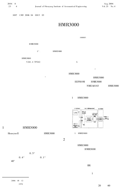
机器人导航中数字罗盘HMR3000的数据处理方法
式中, 系统状态转移矩阵: 1 * #& 5 1 + & 4 ’ 1
[ ]
(3)
,& 是协方差为 - 的系统噪声矩阵, ! & 是系 统噪声矩阵 的驱动矩阵, 本系统 中为 .。系统 的 量测方程为: / & 4 0& )& 5 1& (8) 式中 0& 为系统量测矩阵, 本系统中为 . 。 1& 是协 方差为 $ 的量测噪声矩阵。则通过下面的公式, 就可以估计出机器人的航向值: 2 & 5 1 + & 4 # & 5 1+ & ) 2 & +& ) 3 & 5 1 + & 4 # & 5 1+ & 3 & + & #
*+,$"""
的 数 据 处 理 方 法
邓鲁华- 宗光华- 王- 巍
( 北京航空航天大学 机械工程及自动化学院,北京 - !"""%$)
摘- 要: 介绍了 *+,$""" 型数字罗盘的主要性能, 根据罗盘在移动机器人导航 中的应用, 对航向 和俯 仰、 横滚输出数据设计了不同的卡尔 曼滤波 器, 有效地消 除了罗 盘输出 数据的 波动, 使机器 人姿 态测量精度稳定在 !. 左 右, 证 明了 *+,$""" 型数 字罗 盘在 机器人 导航 领域应 用的 良好效 果。 关 键词: *+,$""" 数字罗盘; 机 器人; 导航;卡尔曼滤波 中图 分类号: /’)!0 ) ; 12’)’ 文献标识码: 3
- 1、下载文档前请自行甄别文档内容的完整性,平台不提供额外的编辑、内容补充、找答案等附加服务。
- 2、"仅部分预览"的文档,不可在线预览部分如存在完整性等问题,可反馈申请退款(可完整预览的文档不适用该条件!)。
- 3、如文档侵犯您的权益,请联系客服反馈,我们会尽快为您处理(人工客服工作时间:9:00-18:30)。
例子: HPR输出带有磁场报警或警告条件
$PTNTHPR,218.7,N.P.1.5,N,0.8,N ** hh <cr><lf> $PTNTHPR,218.7,O.1.5,N,0.8,N ** hh <cr><lf> $PTNTHPR,P.1.5,N,0.8,N ** hh <cr><lf>
N表明正常状态 O表明磁场值高位警告(High warning) P表明磁场值高位报警(High alarm)
罗盘的标定是依照制造厂商规定的标定步骤来完成的。在这一过程中罗盘为补偿算法收集数据。这一标定过
程的目的是对于主平台系统在许多可能的方向下的磁场分量进行采样。将主平台系统旋转360度或使其行驶一 个圆圈(如果主平台是车辆的话),,可使罗盘对它所在的磁场环境进行采样。
HMR3000的标定既可以使用插入的标定方法(Built-in Calibration Method ),也可以使 用PC演示软件,两者标定的结果是一样的。
缓慢地转动平台两周,在平台允许范围内尽可能多地变化俯仰和横滚角度。通常这一过程需进行2分钟。
水平:HMR3000带有电子常平架,所以不需使罗盘完全水平,但是为获得最大的倾斜变化范围,当运载工具或 平台处于正常工作位置时,罗盘应安装成水平状态。
方向: 罗盘的正向可以和平台的正向成任意夹角。使用偏向角( Deviation )参数将罗盘的磁方 向转化为运载工具或平台的磁方向或真值方向。
调节磁场计的增益:用户可以调节HMR3000的磁场计增益,以便在安装时获得最优的特性,对罗盘组态输出HP R句子,如果磁场状态指示O或P,则降低磁场计增益。见HPR信息的叙述和磁场计报警和警告阈值的说明。
名称 TxD/A RxD/B GND 6 - 15V
5V
In / Out Out In In In In
针号 2 3 5 9 8
说明 RS232发送 / RS485发送-接收信号 RS232接收 / RS485发送-接收返回 电源和信号的公共地 未稳压的电源输入 经过稳压的电源输入
HMR3000在平常操作时的管脚定义 注意:在8脚上加的电压不要超过+5.5V,以免对元件造成损坏。
GND 5 Pwr 9
VAC
+12VDC
DB9 socket connector
RS-485
GND +12V
图2
RS485 和计算机的连接
HMR3000罗盘模块的RS485接口为半双工,即发射和接收电路使用同一对传输线。HMR3000必须禁止它的 发射器允许接收来自主机的字符。如果罗盘工作在" Run"的模式下,例如产生重复 的输出,那么" Run / Stop "的插脚(第6号插脚)在主机试图发送命令前应强制其为低电平(见“ 硬件 中断”一节的叙述)。
2.3 电连接 HMR3000到计算机RS232口的连接图
未稳压的电源输入
稳压的电源输入
2.4 通讯 - RS232选项
HMR3000与外部的主机通过RS232或RS485的标准,使用简单的ASCII指令字符串进行通讯。主机可通过这 些指令直接操作HMR3000。选择RS232通讯方式,有一个对用户友好的图形接口软件,可用于对罗盘进行直 接操作。
激活 Display \ View 界面,Display \ Monitor NMEA Sentences 界面来看输出。
Diagnostics \ View Log 是另一种检查罗盘数据的选择。注意要使" Log all messages “ 选择被 激活(在Diagnostics \ Options 菜单中的logging一页).
2. 开始了解HMR3000
2.1 辨别产品 HMR3000罗盘模块有三种不同的选型: (1) 带有RS232或RS485接口的电路板 (2) 带有RS232或RS485接口,带有外壳的罗盘模块 (3) 演示装置(只有RS232接口) 在选型(1)中,接口型式清楚地标在线路板上,在选型(2)中,清楚地标在产品标签上。 选型(3)只有RS232接口。
2.10 标定
所有的磁罗盘必须标定,来补偿地磁场外的其它磁场,以获得精确的航向。地磁场外的磁场是由主平台产生 的,因此与罗盘的安装位置有关。通过执行一个简单的程序,HMR3000可以补偿 诸如硬铁磁场的静态环境磁场,经标定程序发现的磁场分量对于罗盘的特定的位置和方向是有效的。如果罗 盘改变了安装位置或平台的磁特性发生了变化,罗盘需重新标定,否则会产生航向误差。
插入的标定方法 ( Built-in Calibration Method , 这种方法用于当硬铁磁场较小时)
这一方法使用迭代的过程来计算硬铁偏置.通常情况下275次迭代可以得出满意的结果.标定的过程一直继续直 到达到这一迭代次数.将HMR3000置于标定模式下 (发给命令:#F33.4=0*51<CR><lf> ) 缓慢地转动平台两周,在平台允许范围内尽可能多地变化俯仰和横滚角度.通常这一过程需进行2分钟. 通过命令 #I26C?*31<CR><lf> 来检查迭代次数.HMR3000将回答 #nnnn*hh<CR><lf> 信息,其中nnnn为迭代次数. 如果该值小于275,继续进行标定过程直到该值达到275为止。 在这一过程的最后发出指令 ( #F2FE.2=1*67<CR><lf> ) 将结果存于EEPROM中. 将罗盘返回操作模式. (发给指令: #F33.4=1*50<CR><lf>)
在PC演示界面下激活 " Tune Parameters " 的菜单,(从parameter 菜单或使用Tune 按钮).
罗盘处于RUN模式下(连续输出), 没有信号传出(所有输出句子的输出速率在出厂时设置为0).
Hale Waihona Puke 设定HPR句子的输出速率为825(Tune Page \ Serial Output),现在罗盘可以按每分钟825条句子 的速率输出航向、俯仰和横滚数据。
0<S<1 L = 整数 >1 L = 0 表示不执行
L < 256
偏向角 Deviation
偏向角
General page
罗盘的正向方向和平台的正向方向的
夹角。在罗盘的指向上加上偏向角得
± 0 - 180 ° ± 0 - 3200 mils
到平台的指向
2.8 通讯 - RS485选项
带有RS485接口的HMR3000的操作和组态通过主机的直接命令输入来完成.图2为HMR3000和计算机的连接 图。
下面是一些可以在安装时和经常地访问的基本参数。控制磁场计操作、航向输出和报警阈值等的高级参数将 在”组态参数”(Configuration Parameters section)一节中叙述。
2.7 使用PC演示界面
激活 Tune Parameters 的按钮进行组态. (下表为安装时和经常访问的参数)
2.5 得到HMR3000的输出的数据
当电源和接口电缆连接好,软件在PC机中安装好以后,便可以开始从HMR3000获取罗盘数据了。
在PC演示软件的窗口下双击图标,选择相应的COM口和19200波特率. (工厂设定为19200).
在屏幕上将会出现信息块,表明微程序语言的版本,出现这一信息块表明安装和连接正确。
RS232选项
连同罗盘模块提供给客户一套PC演示接口软件,客户可以通过RS232口对HMR3000进行组态。这个软件适 用于与IBM PC兼容的计算机,带有MS Windows 3.11, Windows 95或Windows 97。允许HMR3000和PC机之间通讯,对HMR3000组态,接收罗盘的输出,记录和获得罗盘的信息。这个P C演示接口软件还可以演示输入/输出的选项,是学习了解HMR3000的重要的工具.
Output Message CCD的NMEA句子输出速率(单位是每
0 - 1200 / min
and Rate
分钟句子数目)
数据滤波器
TC1和TC2
0 - 255
Data Filters
用于IIR滤波器1和2的连续的时间常数
1 = 72 ms
航向输出
L和S
Heading Output 非线性滤波器的平滑系数
功能
参数 / 说明
位于
范围
磁偏角 Declination
磁偏角 磁北和地理北的夹角。在磁航向 上加上磁偏角得到航向真值
General page
± 0 - 180 ° ± 0 - 3200 mils
输出信息和速率 HDG,HDT,XDR,HPR,RCD, Serial Output page 没有或所有
PC演示软件界面的方法 PC Demo Interface Software Method
三维标定 3D Calibration:
当硬铁磁场较大时,建议使用这一方法。PC演示界面将在标定过程中收集磁场矢量信息并进行分析,以找出 硬铁偏置量。
在PC演示软件下,进入Diagnostics ,然后进入 Perform 3D Calibration 菜单.
2.2 安装
对于演示装置,接口和电源电缆包括在其中(参见“电连接”一节)
对于其它的HMR3000选型,用户自己应按照下表制作带有标准9针母接头电缆。电源只接到第9针或第8针上 。对于多数应用,连接好表 1中所列出的几个管脚就可以了,而第1、4、6和7针 在HMR3000的工作中执行特定的功能,平时应保持其开路(维持逻辑高电平)
注:为使 View \ Interface被激活,应选择一个非零的HPR信息速率。罗盘显示航向和倾斜的 信息需要快速的处理器(Pentium),以便足够快地响应罗盘的输出。速度较慢的计算机会在罗盘输出和显示 间有较长的延时。所有被选择的NMEA信息将在" Display \ Monitor NMEA Sentences "中被更新。