SIHLZ34中文资料
SSL34中文资料

VOLTAGE RANGE 20 to 40 Volts SSL32 THRU SSL34CURRENT3.0 AmpereFEATURES• Low profile surface mount package • Built-in strain relief• High switching speed, low V F • Low voltage drop, high efficiency• For use in low voltage high frequency inverters, Free willing ,and polarity protection applications •Guardring for over voltage protectionMECHANICAL DATA• Case: Transfer molded plastic• Epoxy :UL 94V-0 rate flame retardant• Lead: Solder plated, solderable per MIL-STD-750 method 2026• Polarity: Color band denotes cathode end•Weight: 0.007 ounce, 0.25 gram-DO-214AB(SMC)MAXIMUM RATINGS AND ELECTRICAL CHARACTERISTICS• Ratings at 25℃ ambient temperature unless otherwise specified. • Single phase, half wave, 60Hz, resistive or inductive load. •For capacitive load derate current by 20%. SYMBOLS SSL32 SSL33SSL34 UNIT Maximum Repetitive Peak Reverse Voltage V RRM 20 30 40 Volts Maximum RMS Voltage V RMS 20 30 40 Volts Maximum DC Blocking Voltage V DC 2030 40 Volts Maximum Average Forward Rectified Current at T L see figure1 T L =95℃ I (AV) 3.0 Amps Peak Forward Surge Current8.3ms single half sine-wave superimposed on rated load (JEDEC method)I FSM 80AmpsMaximum Instantaneous Forward Voltage @ 3.0A (Note1)V F 0.380.45 Volts T A = 25℃ 0.5 Maximum DC Reverse Current at rated DC Blocking Voltage per element T A = 100℃ I R 10.0 mAR θJA 55 Typical Thermal Resistance (Note 2) R θJL 12℃/W Operating Junction Temperature T J (-55 to +150) ℃Storage Temperature RangeT STG(-55 to +150)℃Notes:1. Pulse test: 300μs pulse width,1% duty cycle2. PCB mounted with 0.55”×0.55”(14.0cm ×14.0cm) copper padsVOLTAGE RANGE 20 to 40Volts SSL32 THRU SSL34CURRENT 3.0 AmpereFIG.2-MAXIMUM NON-REPETITIVE PEAKCHARACTERISTICS80CURRENT,(A)PEAKFORWARDSURGENUMBER OF CYCLES AT 60 HzFORWARD SURGE CURRENTFIG.4-TYPICAL REVERSEDERATING CURVEFIG.1-TYPICAL FORWARD CURRENT150175125751002.050025AVERAGEFORWARDCURRENT,(A)FIG.3-TYPICAL INSTANTANEOUSFORWARD CHARACTERISTICSAMBIENT TEMPERATURE, (°C)(mA)(A)100FIG.5-TYPICAL JUNCTION CAPACITANCE0.110REVERSE VOLTAGE,(V)JUNCTIONCAPACITANCE,(pF)INSTANTANEOUSFORWARDCURRENT,INSTANTANEOUSREVERSECURRENT,1.010100REVERSE VOLTAGE,(%)1.03.040RATING AND CHRACTERISTIC CURVES SSL32 THRU SSL34200.11.010INSTANTANEOUS FORWARD VOLTAGE,(V)。
PNOZ m EF 8DI4DO操作手册说明书

PNOZ m EF 8DI4DO}Configurable control systems PNOZmulti 2This document is a translation of the original document.All rights to this documentation are reserved by Pilz GmbH & Co. KG. Copies may be made for internal purposes. Suggestions and comments for improving this documentation will be gratefully received.Pilz®, PIT®, PMI®, PNOZ®, Primo®, PSEN®, PSS®, PVIS®, SafetyBUS p®,SafetyEYE®, SafetyNET p®, the spirit of safety® are registered and protected trademarks of Pilz GmbH & Co. KG in some countries.SD means Secure Digital1.2Using the documentation4 1.3Definition of symbols42.2Unit features6 2.3Front view73.2System requirements8 3.3Safety regulations8 3.3.1Use of qualified personnel8 3.3.2Warranty and liability9 3.3.3Disposal9 3.3.4For your safety94.2Functions10 4.3System reaction time10 4.4Block diagram105.2Dimensions in mm11 5.3Connecting the base unit and expansion modules116.2Connection13 6.3Download modified project to the PNOZmulti system1410.2Accessories221Introduction1.1Validity of documentationThis documentation is valid for the product PNOZ m EF 8DI4DO. It is valid until new docu-mentation is published.This operating manual explains the function and operation, describes the installation andprovides guidelines on how to connect the product.1.2Using the documentationThis document is intended for instruction. Only install and commission the product if youhave read and understood this document. The document should be retained for future ref-erence.1.3Definition of symbolsInformation that is particularly important is identified as follows:NOTICEThis describes a situation in which the product or devices could be dam-aged and also provides information on preventive measures that can betaken. It also highlights areas within the text that are of particular import-ance.INFORMATIONThis gives advice on applications and provides information on special fea-tures.2Overview2.1Scope of supply}Expansion module PNOZ m EF 8DI4DO}Jumper2.2Unit featuresUsing the product PNOZ m EF 8DI4DO:Expansion module for connection to a base unit from the configurable control systemPNOZmulti 2 .The product has the following features:}Can be configured in the PNOZmulti Configurator}Semiconductor outputs:4 safety outputsDepending on the application, up to PL e of EN ISO 13849-1 and up to SIL CL 3 of ENIEC 62061}8 inputs for connecting, for example:–E-STOP pushbutton–Two-hand button–Safety gate limit switch–Start button–Light beam devices–Scanner–Enabling switch–PSEN–Operating mode selector switch}LED for:–Error messages–Diagnostics–Supply voltage–Output circuits–Input circuits}Test pulse outputs used to monitor shorts across the inputs}Monitoring of shorts between the safety outputs}Plug-in connection terminals:Either spring-loaded terminal or screw terminal available as an accessory (see orderreference)}Please refer to the document "PNOZmulti System Expansion" for the PNOZmulti base units that can be connected.2.3Front viewKey:}0 V, 24 V: Supply connections}Inputs I0 – I7}Outputs O0 – O3}LEDs:–POWER–Run–Diag–Fault–I Fault–O Fault3Safety3.1Intended useThe expansion module may only be connected to a base unit from the configurable systemPNOZmulti 2 (please refer to the document "PNOZmulti System Expansion" for details ofthe base units that can be connected).The configurable system PNOZmulti 2 is used for the safety-related interruption of safetycircuits and is designed for use in:}Emergency stop equipment}Safety circuits in accordance with VDE 0113 Part 1 and EN 60204-1The following is deemed improper use in particular:}Any component, technical or electrical modification to the product}Use of the product outside the areas described in this manual}Use of the product outside the technical details (see Technical details [ 17]).NOTICEEMC-compliant electrical installationThe product is designed for use in an industrial environment. The productmay cause interference if installed in other environments. If installed in otherenvironments, measures should be taken to comply with the applicablestandards and directives for the respective installation site with regard to in-terference.3.2System requirementsPlease refer to the "Product Modifications PNOZmulti" document in the "Version overview"section for details of which versions of the base unit and PNOZmulti Configurator can beused for this product.3.3Safety regulations3.3.1Use of qualified personnelThe products may only be assembled, installed, programmed, commissioned, operated,maintained and decommissioned by competent persons.A competent person is someone who, because of their training, experience and current pro-fessional activity, has the specialist knowledge required to test, assess and operate thework equipment, devices, systems, plant and machinery in accordance with the generalstandards and guidelines for safety technology.It is the company’s responsibility only to employ personnel who:}Are familiar with the basic regulations concerning health and safety / accident preven-tion}Have read and understood the information provided in this description under "Safety"}And have a good knowledge of the generic and specialist standards applicable to the specific application.3.3.2Warranty and liabilityAll claims to warranty and liability will be rendered invalid if}The product was used contrary to the purpose for which it is intended}Damage can be attributed to not having followed the guidelines in the manual}Operating personnel are not suitably qualified}Any type of modification has been made (e.g. exchanging components on the PCB boards, soldering work etc.).3.3.3Disposal}When decommissioning, please comply with local regulations regarding the disposal of electronic devices (e.g. Electrical and Electronic Equipment Act).3.3.4For your safetyThe unit meets all the necessary conditions for safe operation. However, you should alwaysensure that the following safety requirements are met:}This operating manual only describes the basic functions of the unit. The expanded functions are described in the PNOZmulti Configurator's online help. Only use thesefunctions once you have read and understood the documentations.}Do not open the housing or make any unauthorised modifications.}Please make sure you shut down the supply voltage when performing maintenance work (e.g. exchanging contactors).Function description4Function description4.1Integrated protection mechanismsThe relay conforms to the following safety criteria:}The circuit is redundant with built-in self-monitoring.}The safety function remains effective in the case of a component failure.}The safety outputs are tested periodically using a disconnection test.4.2FunctionsThe expansion module provides additional inputs and additional semiconductor outputs.The function of the inputs and outputs on the control system depends on the safety circuitcreated using the PNOZmulti Configurator. A chip card is used to download the safety cir-cuit to the base unit. The base unit has 2 microcontrollers that monitor each other. Theyevaluate the input circuits on the base unit and expansion modules and switch the outputson the base unit and expansion modules accordingly.The online help on the PNOZmulti Configurator contains descriptions of the operatingmodes and all the functions of the PNOZmulti control system, plus connection examples.4.3System reaction timeCalculation of the maximum reaction time between an input switching off and a linked out-put in the system switching off is described in the document "PNOZmulti System Expan-sion".4.4Block diagram5Installation5.1General installation guidelines}The unit should be installed in a control cabinet with a protection type of at least IP54.}Fit the safety system to a horizontal mounting rail. The venting slots must face upward and downward. Other mounting positions could damage the safety system.}Use the locking elements on the rear of the unit to attach it to a mounting rail.}In environments exposed to heavy vibration, the unit should be secured using a fixing element (e.g. retaining bracket or end angle).}Open the locking slide before lifting the unit from the mounting rail.}To comply with EMC requirements, the mounting rail must have a low impedance con-nection to the control cabinet housing.}The ambient temperature of the PNOZmulti units in the control cabinet must not exceed the figure stated in the technical details, otherwise air conditioning will be required.NOTICEDamage due to electrostatic discharge!Electrostatic discharge can damage components. Ensure against dischargebefore touching the product, e.g. by touching an earthed, conductive sur-face or by wearing an earthed armband.5.2Dimensions in mm5.3Connecting the base unit and expansion modulesConnect the base unit and the expansion modules as described in the operating manualsfor the base modules.}The terminator must be fitted to the last expansion module}Install the expansion module in the position configured in the PNOZmulti Configurator.The position of the expansion modules is defined in the PNOZmulti Configurator. The ex-pansion modules are connected to the left or right of the base unit, depending on the type.Please refer to the document "PNOZmulti System Expansion" for details of the number of modules that can be connected to the base unit and the module types.6Commissioning6.1General wiring guidelinesThe wiring is defined in the circuit diagram of the PNOZmulti Configurator.Please note:}Information given in the Technical details [ 17] must be followed.}Use copper wire that can withstand 75° C.6.2ConnectionSupply voltageConnection examples for the input circuitConnection examples for semiconductor outputs*Two loads may be connected to each safety output with advanced fault detection, even onapplications in accordance with EN IEC 62061, SIL CL 3. Prerequisite: Feedback loop isconnected, shorts across contacts and external power sources are excluded (e.g. throughseparate multicore cables). Please note that, in the event of an error in the feedback loop,the safety system switches to a safe condition and shuts down all the outputs.Connection examples for feedback loop6.3Download modified project to the PNOZmulti systemAs soon as an additional expansion module has been connected to the system, the projectmust be amended using the PNOZmulti Configurator. Proceed as described in the operat-ing instructions for the base unit.NOTICEFor the commissioning and after every program change, you must checkwhether the safety devices are functioning correctly.Operation7OperationWhen the supply voltage is switched on, the PNOZmulti safety system copies the configur-ation from the chip card.The LEDs “POWER”, “DIAG”, “FAULT”, “IFAULT” and “OFAULT” will light up on the baseunit.7.1MessagesLegendLED onLED flashesLED off8Technical detailsApprovals BG, CCC, CE, GOST, TÜV, cULus Listed Application range Failsafefor Supply to the SC outputsVoltage24 VKind DCVoltage tolerance-20 %/+25 %Current load capacity at UB8,0 APotential isolation yesSupply voltagefor Module supplyinternal Via base unitVoltage24,0 VKind DCCurrent consumption39 mAPower consumption1,0 WMax. power dissipation of module4,50 WStatus indicator LEDInput voltage in accordance with EN 61131-2 Type 124 V DCInput current at rated voltage 5 mAInput current range2,5 - 5,3 mAPulse suppression0,5 msMaximum input delay8 msductor outputs4Switching capabilityVoltage24 VTyp. output current at "1" signal and rated voltage ofsemiconductor output2,00 APermitted current range0,00 - 2,50 AResidual current at "0" signal0,05 mAMax. transient pulsed current12 AMax. capacitive load 1 µFMax. internal voltage drop500 mVMax. duration of off time during self test330 µsSwitch-off delay 3 msIn accordance with the standard EN 60068-2-14Temperature range0 - 60 °CForced convection in control cabinet off55 °CStorage temperatureIn accordance with the standard EN 60068-2-1/-2Temperature range-25 - 70 °CClimatic suitabilityIn accordance with the standard EN 60068-2-30, EN 60068-2-78 Condensation during operation Not permittedEMC EN 61131-2VibrationIn accordance with the standard EN 60068-2-6Frequency5,0 - 150,0 HzAcceleration1gShock stressIn accordance with the standard EN 60068-2-27Acceleration15gDuration11 msMax. operating height above sea level2000 mAirgap creepageIn accordance with the standard EN 61131-2Overvoltage category IIPollution degree2Rated insulation voltage30 VProtection typeIn accordance with the standard EN 60529Mounting area (e.g. control cabinet)IP54Housing IP20Potential isolation between SC output and system voltage Type of potential isolation Basic insulationDIN railTop hat rail35 x 7,5 EN 50022Recess width27 mmMax. cable lengthMax. cable length per input1,0 kmBottom PC Front PC TopPCConnection type Spring-loaded terminal, screw terminal Mounting typeplug-inConductor cross section with screw terminals 1 core flexible0,25 - 2,50 mm², 24 - 12 AWG 2 core with the same cross section, flexible without crimp connectors or with TWIN crimp connectors 0,20 - 1,50 mm², 24 - 16 AWG Torque setting with screw terminals0,50 NmConductor cross section with spring-loaded terminals:Flexible with/without crimp connector0,20 - 2,50 mm², 24 - 12 AWG Spring-loaded terminals: Terminal points per connec-tion2Stripping length with spring-loaded terminals 9 mm Dimensions Height 101,4 mm Width 22,5 mm Depth 120,0 mm Weight105 gWhere standards are undated, the 2012-04 latest editions shall apply.8.1Safety characteristic dataNOTICEYou must comply with the safety-related characteristic data in order to achieve the required safety level for your plant/machine.SC inputs 2-channel PL e Cat. 4SIL CL 34,27E-1120SC inputs1-ch., pulsedlight barrier PL eCat. 4SIL CL 32,10E-1020with ad-vanced faultdetection PL e Cat. 4SIL CL 32,12E-1120SC outputs1-channel PL d Cat. 2SIL CL 22,29E-1020SC outputs2-channel PL e Cat. 4SIL CL 31,64E-1020All the units used within a safety function must be considered when calculating the safetycharacteristic data.INFORMATIONA safety function's SIL/PL values are not identical to the SIL/PL values ofthe units that are used and may be different. We recommend that you usethe PAScal software tool to calculate the safety function's SIL/PL values.Supplementary data9Supplementary data9.1Permitted ambient temperature Tamb dependent on the totalcurrent IsumOrder reference10Order reference 10.1Product10.2AccessoriesConnection terminalsTerminator, jumperSupportTechnical support is available from Pilz round the clock. Americas Brazil+55 11 97569-2804Canada+1 888-315-PILZ (315-7459)Mexico+52 55 5572 1300USA (toll-free)+1 877-PILZUSA (745-9872)Asia China+86 21 60880878-216 Japan+81 45 471-2281South Korea +82 31 450 0680Australia +61 3 95446300Europe Austria+43 1 7986263-0Belgium, Luxembourg +32 9 3217575France+33 3 88104000Germany+49 711 3409-444Ireland+353 21 4804983Italy+39 0362 1826711Scandinavia +45 74436332Spain+34 938497433Switzerland +41 62 88979-30The Netherlands +31 347 320477Turkey+90 216 5775552United Kingdom +44 1536 462203You can reach our international hotline on: +49 711 3409-444 ****************C M S E ®, I n d u r a N E T p ®, P A S 4000®, P A S c a l ®, P A S c o n fi g ®, P i l z ®, P I T ®, P L ID ®, P M C p r i m o ®, P M C p r o t e g o ®, P M C t e n d o ®, P M D ®, P M I ®, P N O Z ®, P r i m o ®, P SE N ®, P S S ®, P V I S ®, S a f e t y B U S p ®, S a f e t y E Y E ®, S a f e t y N E T p ®, T h E S P I r I T O f S A f E T Y ® a r e r e g i s t e r e d a n d p r o t e c t e d t r a d e m a r k s o f P i l z G m b h & C o . K G i n s o m e c o u n t r i e s . W e w o u l d p o i n t o u t t h a t p r o d u c t f e a t u r e s m a y v a r y f r o m t h e d e t a i l s s t a t e d i n t h i s d o c u m e n t , d e p e n d i n g o n t h e s t a t u s a t t h e t i m e o f p u b l i c a t i o n a n d t h e s c o p e o f t h e e q u i p m e n t . W e a c c e p t n o r e s p o n s i b i l i t y f o r t h e v a l i d i t y , a c c u r a c y a n d e n t i r e t y o f t h e t e x t a n d g r a p h i c s p r e s e n t e d i n t h i s i n f o r m a t i o n . P l e a s e c o n t a c t o u r T e c h n i c a l S u p p o r t i f y o u h a v e a n y q u e s t i o n s .Pilz develops environmentally-friendly products using ecological materials and energy-saving technologies. Offices and production facilities are ecologically designed, environmentally-aware and energy-saving. So Pilz offers sustainability, plus the security of using energy-efficient products and environmentally-friendly solutions.Pilz Gmbh & Co. KG felix-Wankel-Straße 2 73760 Ostfildern, Germany Tel.: +49 711 3409-0 fax: +49 711 3409-133 100X X X X -D E -0X 0-0-1-3-000, 2015-00 P r i n t e d i n G e r m a n y © P i l z G m b h & C o . K G , 20151002661-E N -03, 2016-02 P r i n t e d i n G e r m a n y © P i l z G m b H & C o . K G , 2015。
HFS34中文资料

?=H23+A>.23=,HEB@;HI9I<G<B9MnoEJIB@D<;@C<DH@EDH-L@G@D>;@9>G9C 9D;CEJDI@D>?EB<HEG;<G@D>@D=EGC9I@ED0ONFCH?{CG?HMCIHM7CLCHA {C;AL;G.IOHNCHA *IF?-;SIONnp5HCN u GGDY]R\8*}3no CM ;H ?HPCLIHG?HN;F @LC?H>FS JLI>O=N g JF?;M?G;LE MJ?=C;F =I>?dpppe QB?H IL>?L i:?9G9:I<G@HI@::JGK<H.;R i -I;>z OLL?HN PM i x G<C?HN 4?GJ i dokxex G<C?HN 4?GJ?L;NOL?d x G<C?HN 4?GJ?L;NOL?d .;R i -I;>z OLL?HN PM i x G<C?HN 4?GJ i dqkxex G<C?HN 4?GJ?L;NOL?d e x G<C?HN 4?GJ?L;NOL?d ex G<C?HN 4?GJ?L;NOL?d x G<C?HN 4?GJ?L;NOL?d {CM=F;CG?L4BCM >;N;MB??N CM @IL NB?=OMNIG?LMY L?@?L?H=?i x FF NB?MJ?=C@C=;NCIHM ;L?MO<D?=N NI =B;HA?QCNBION HINC=?i7?=IOF>HIN ?P;FO;N?;FF NB?J?L@ILG;H=?;H>;FF NB?J;L;G?N?LM @IL ?P?LS JIMMC<F?;JJFC=;NCIH i 4BOM NB?OM?L MBIOF><?CH ;LCABN JIMCNCIH NI =BIIM?NB?MOCN;<F?JLI>O=N @IL NB?CL IQH ;JJFC=;NCIH i +@NB?L?CM ;HS KO?LS g JF?;M?=IHN;=N *IHA@;@IL NB?N?=BHC=;F M?LPC=?i *IQ?P?L g CN CM NB?OM?LYM L?MJIHMC<CFCNS NI >?N?LGCH?QBC=B JLI>O=N MBIOF><?OM?>IHFS iV 8C;G?H *IHA@;|F?=NLI;=IOMNC=z I ig -N>i x FF LCABNM I@*IHA@;;L?L?M?LP?>i-I ;>z O L L ?H N d 2.3e d x e-I ;>z O L L ?H N d 2.3e d x e-I ;>z O L L ?H N d 2.3e d x e-I ;>z O L L ?H N d 2.3e d x e-I ;>z O L L ?H N d 2.3e d x e-I ;>z O L L ?H N d 2.3e d x e.;R i -I;>z OLL?HN PM i x G<C?HN 4?GJ i dpkxe.;R i -I;>z OLL?HN PM i x G<C?HN 4?GJ i drkxe.;R i -I;>z OLL?HN PM i x G<C?HN 4?GJ i dskxe.;R i -I;>z OLL?HN PM i x G<C?HN 4?GJ i dlkkxenqhmkhnk kmkp k lkkokqkskmk lk lp nkokhmkhnkkmklkkokqkskmkllip okqkp hmkhnk kmkklkkokqkskrklmok nkhmkhnkkmkk lkkokqkskoklmlsskhmkhnkkmkk lkkokqkskpkokp ll mkls hmkhnkkmkk lkkokqkskoknk sklkklmk lm p。
防喷器规格及技术参数(全表)
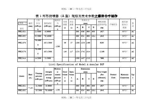
表1环形防喷器(A型)规格及技术参数之蔡仲巾千创作
List1:Specification of Model A Annular BOP
时间:二O二一年七月二十九日
表2 环形防喷器(D型)规格及技术参数
注:以上所列技术参数为基本型.
List2:Specification of Model D Annular BOP
时间:二O二一年七月二十九日
表3RSC型闸板防喷器规格及技术参数
时间:二O二一年七月二十九日
时间:二O二一年七月二十九日
续表3 RSC闸板防喷器规格及技术参数
时间:二O二一年七月二十九日
注:以上所列技术参数为基本型.
List3:Specification of Model RSC Ram BOP
时间:二O二一年七月二十九日
表4RSF型板防喷器格及技术参数
时间:二O二一年七月二十九日
注:以上所列技术参数为基本型.
时间:二O二一年七月二十九日
List4:Specification of Model RSC Ram BOP
时间:二O二一年七月二十九日
表5RSL型板防喷器格及技术参数
注:以上所列技术参数为基本型.
List5:Specification of Model RSL Ram BOP
时间:二O二一年七月二十九日
时间:二O二一年七月二十九日
时间:二O二一年七月二十九日。
维智WSDA系列伺服驱动器用户手册(EtherCAT总线通信型)-R4
维智WSDA系列伺服驱动器用户手册(EtherCAT总线通信型)版次:2020年10月12日第4版作者:产品应用测试部上海维宏电子科技股份有限公司目录1 安全注意事项 (1)1.1 警告 (1)1.2 注意 (2)2 基本信息 (3)2.1 前面板结构 (3)2.2 铭牌 (4)2.3 控制模式 (5)2.4 规格与功能 (5)2.4.1 基本规格 (5)2.4.2 从站规格 (7)2.4.3 基本功能 (8)2.4.4 保护功能 (8)2.5 产品安装 (8)2.6 系统接线图 (10)3 配线 (13)3.1 主回路接线 (13)3.1.1 端子 (13)3.1.2 电线规格 (14)3.1.3 接线说明 (17)3.2 USB通讯接口CN1接线 (18)3.2.1 端口定义 (18)3.2.2 线缆 (19)3.3 总线接口 CN2A/B 接线 (20)3.3.1 接线图 (20)3.3.2 线缆 (20)3.4 电机编码器线接口CN4接线 (21)3.4.1 端口定义 (21)3.4.2 说明 (22)3.4.3 线缆 (23)3.5 外置再生制动电阻器连接 (24)4 驱动器面板 (29)4.1 概述 (29)4.2 监视器模式 (31)4.3 参数设定模式 (41)4.4 EEPROM 写入模式 (41)4.5 辅助功能模式 (42)4.5.1 概述 (42)4.5.2 设置站别名 (44)4.5.3 解除报警 (44)4.5.4 试运行电机 (45)4.5.5 清零绝对值编码器 (45)4.5.6 初始化参数 (46)4.5.7 解除前面板锁定 (46)4.5.8 注册驱动器 (46)4.5.9 初始化对象字典 (47)4.6 驱动器面板锁定 (48)5 电机试运行 (48)5.1 准备工作 (48)5.2 进行基本设定 (48)5.2.1 打开伺服 (49)5.2.2 选择电机旋转方向 (49)5.2.3 启用超程防止功能 (49)5.2.4 设定电机过载率 (50)5.2.5 启用制动器 (50)5.2.6 伺服断开及报警时停止电机 (50)5.3.1 使用 iMotion 软件 (51)5.3.2 使用驱动器面板 (51)5.4 故障排查 (51)6 控制系统连接 (54)6.1 选择系统类型 (54)6.2 设置关联参数 (54)6.2.1 设置控制系统参数 (54)6.2.2 设置维智伺服驱动器参数 (55)6.3 设置站别名 (55)6.4 设定基准或回机械原点 (55)6.4.1 设定基准 (55)6.4.2 回机械原点 (56)6.5 运行电机 (56)7 绝对式系统 (56)7.1 安装与更换电池 (56)7.2 自制绝对式编码器电缆 (58)7.3 启用绝对值功能 (58)7.4 启用无限旋转绝对式功能 (58)8 增益调整 (58)8.1 准备工作 (58)8.1.1 设定驱动禁止输入 (59)8.1.2 设定转矩限制 (59)8.1.3 设定过速度保护 (59)8.1.4 设定位置偏差过大保护 (59)8.1.5 设定电机可动范围 (60)8.2 推定惯量比 (60)8.3 设置自适应滤波器 (61)8.3.1 操作步骤 (62)8.3.2 故障排查 (62)8.3.3 相关信息 (63)8.4 自动调整增益 (63)8.4.1 操作步骤 (64)8.4.3 相关信息 (65)8.5 手动调整增益 (67)8.5.1 执行基本调整 (68)8.5.2 切换增益 (69)8.5.3 抑制机械共振 (75)8.5.4 设置 2 段转矩滤波器 (76)8.6 总线控制系统调整增益 (77)9 驱动器注册 (77)9.1 获取序列号 (77)9.1.1 通过 iMotion 软件 (78)9.1.2 通过驱动器面板 (79)9.2 获取注册码 (80)9.3 注册驱动器 (81)10 异常与对策 (82)10.1 异常时应对思路 (82)10.2 警告 (83)10.2.1 查找警告 (83)10.2.2 警告码 (83)10.3 SDO传输中止码 (84)10.4 错误码一览表 (85)10.5 错误码详情 (90)10.5.1 Err10系列 (90)10.5.2 Err20系列 (97)10.5.3 Err30系列 (101)10.5.4 Err40系列 (105)10.5.5 Err50系列 (108)10.5.6 Err70系列 (112)10.5.7 Err80系列 (115)10.5.8 Err90系列 (124)10.5.9 其他错误码 (125)10.5.10 解除错误 (125)11 参数 (126)11.2 [分类 0]基本设定 (126)11.2.1 Pr001 (126)11.2.2 Pr002 (127)11.2.3 Pr003 (127)11.2.4 Pr004 (128)11.2.5 Pr011 (128)11.2.6 Pr012 (129)11.2.7 Pr013 (130)11.2.8 Pr014 (131)11.2.9 Pr015 (131)11.2.10 Pr016 (132)11.2.11 Pr017 (132)11.2.12 Pr018~Pr019 (133)11.2.13 Pr024 (134)11.3 [分类 1]增益调整 (134)11.3.1 Pr100~Pr104 (134)11.3.2 Pr105~Pr109 (136)11.3.3 Pr110 (137)11.3.4 Pr111 (138)11.3.5 Pr112 (138)11.3.6 Pr113 (138)11.3.7 Pr114 (139)11.3.8 Pr115 (140)11.3.9 Pr116 (142)11.3.10 Pr117 (142)11.3.11 Pr118 (142)11.3.12 Pr119 (143)11.3.13 Pr120 (143)11.3.14 Pr121 (144)11.3.15 Pr122 (144)11.3.16 Pr123 (144)11.3.17 Pr124 (145)11.3.19 Pr126 (145)11.3.20 Pr127 (146)11.4 [分类 2]控制抑制功能 (146)11.4.1 Pr200 (146)11.4.2 Pr201~Pr203 (146)11.4.3 Pr204~Pr206 (147)11.4.4 Pr207~Pr209 (149)11.4.5 Pr210~Pr212 (150)11.4.6 Pr214~Pr215 (151)11.4.7 Pr216~Pr217 (151)11.4.8 Pr218~Pr219 (152)11.4.9 Pr220~Pr221 (152)11.4.10 Pr222 (153)11.4.11 Pr223 (154)11.5 [分类 3]速度/转矩控制 (155)11.5.1 Pr300 (155)11.5.2 Pr302 (156)11.5.3 Pr304 (156)11.5.4 Pr312~Pr313 (157)11.5.5 Pr314 (158)11.5.6 Pr317、Pr318、Pr321、Pr322 (158)11.5.7 Pr323 (160)11.5.8 Pr326 (160)11.5.9 Pr327 (161)11.5.10 Pr343 (161)11.5.11 Pr344 (161)11.5.12 Pr345 (162)11.5.13 Pr346 (162)11.6 [分类 4] I / F 监视器设定 (162)11.6.1 Pr400~Pr406 (162)11.6.2 Pr408~Pr411 (165)11.6.3 Pr430 (167)11.6.5 Pr432 (168)11.6.6 Pr433 (168)11.6.7 Pr434 (169)11.6.8 Pr435 (169)11.6.9 Pr436 (170)11.6.10 Pr437 (171)11.6.11 Pr438 (171)11.6.12 Pr439~Pr440 (172)11.6.13 Pr441 (173)11.6.14 Pr449 (173)11.6.15 Pr450 (174)11.7 [分类 5]扩展设定 (174)11.7.1 Pr503 (174)11.7.2 Pr504 (174)11.7.3 Pr505 (175)11.7.4 Pr506 (176)11.7.5 Pr507 (177)11.7.6 Pr508 (177)11.7.7 Pr509 (177)11.7.8 Pr510 (178)11.7.9 Pr511 (179)11.7.10 Pr512 (179)11.7.11 Pr513 (179)11.7.12 Pr514 (180)11.7.13 Pr516 (180)11.7.14 Pr520 (180)11.7.15 Pr521 (181)11.7.16 Pr522 (181)11.7.17 Pr523 (181)11.7.18 Pr524 (181)11.7.19 Pr525 (182)11.7.20 Pr526 (182)11.7.22 Pr533 (184)11.7.23 Pr535 (184)11.7.24 Pr540 (184)11.7.25 Pr541 (185)11.8 [分类 6]特殊设定 (185)11.8.1 Pr601 (185)11.8.2 Pr602 (185)11.8.3 Pr604 (185)11.8.4 Pr607 (186)11.8.5 Pr608 (186)11.8.6 Pr609 (186)11.8.7 Pr611 (187)11.8.8 Pr612 (187)11.8.9 Pr615 (187)11.8.10 Pr617 (188)11.8.11 Pr623 (188)11.8.12 Pr624 (189)11.8.13 Pr627 (189)11.8.14 Pr628 (189)11.8.15 Pr629 (189)11.8.16 Pr630 (190)11.8.17 Pr632 (190)11.8.18 Pr633 (192)11.8.19 Pr638 (192)11.8.20 Pr640 (193)11.8.21 Pr642 (193)11.8.22 Pr643 (194)11.8.23 Pr647 (194)11.8.24 Pr650 (194)11.8.25 Pr651 (195)11.8.26 Pr660 (195)12 EtherCat通信规格 (195)12.2 帧结构 (196)12.3 ESC地址空间 (197)12.4 通信状态 (197)12.5 SDO (198)12.6 PDO (198)12.6.1 PDO映射 (199)12.6.2 分配对象 (200)12.6.3 映射配置 (200)12.7 DC通信同步模式 (201)12.8 SII EEPROM (201)12.9 寻址模式 (201)13 对象字典 (202)13.1 概述 (202)13.1.1 分类 (202)13.1.2 数据类型 (203)13.1.3 相关用语 (203)13.2 通信对象 (204)13.2.1 设备信息 (204)13.2.2 同步管理器通讯类型 (208)13.2.3 PDO通讯 (210)13.2.4 同步管理器 2 和 3 同步对象 (240)13.2.5 对象写入 EEPROM (250)13.2.6 对象恢复出厂 (251)13.2.7 故障履历 (252)13.3 驱动器参数对象 (259)13.3.1 2100h (259)13.3.2 2101h (260)13.3.3 2102h (262)13.3.4 2103h (263)13.3.5 2200h (264)13.4 厂商定义对象 (265)13.5 辅助功能对象 (266)13.5.1 信息监视器对象 (266)13.5.2 多圈绝对式编码器清零 (277)13.6 驱动协议对象 (277)13.6.1 功率驱动系统状态机 (277)13.6.2 控制模式设置 (283)13.6.3 位置控制模式 (287)13.6.4 速度控制模式 (325)13.6.5 转矩控制模式 (335)13.6.6 模式共通功能 (343)14 对象字典一览表 (370)14.1 1000h~1FFFh (370)14.2 2000h~2FFFh (378)14.3 3000h~30FFh (379)14.4 3100h~37FFh (392)14.5 6000h~6FFFh (394)1安全注意事项注意事项根据不遵守可能会造成危害的程度,分为警告和注意类型:警告:特别需要提示的内容,如果不遵守此类信息,可能会造成人身伤害甚至是死亡、机器损坏、或者其他财产损失。
6N134中文资料

6N134中⽂资料FeaturesDual Marked with Device Part Number and DSCC Drawing NumberManufactured and Tested on a MIL-PRF-38534 Certified LineQML-38534, Class H and K Five Hermetically Sealed Package Configurations Performance Guaranteed over -55°C to +125°C ? High Speed: 10 M Bit/sCMR: > 10,000 V/µs Typical 1500 Vdc Withstand Test Voltage2500 Vdc Withstand Test Voltage for HCPL-565X High Radiation Immunity 6N137, HCPL-2601, HCPL-2630/-31 Function Compatibility ? Reliability DataTTL Circuit CompatibilityApplicationsMilitary and SpaceHigh Reliability SystemsTransportation, Medical, and Life Critical SystemsLine ReceiverVoltage Level ShiftingIsolated Input Line Receiver Isolated Output Line Driver Logic Ground Isolation Harsh Industrial EnvironmentsIsolation for Computer,Communication, and Test Equipment SystemsDescriptionThese units are single, dual and quad channel, hermetically sealed optocouplers. The products are capable of operation and storage over the full military temperature range and can be purchased as either standard product or with full MIL-PRF-38534 Class Level H or K testing or from the appropri-ate DSCC Drawing. All devices are manufactured and tested on a MIL-PRF-38534 certified line and are included in the DSCC Quali-fied Manufacturers List QML-38534 for Hybrid Microcircuits.Quad channel devices areavailable by special order in the 16 pin DIP through hole packages.Truth Table(Positive Logic)Multichannel DevicesInput Output On (H)L Off (L)HFunctional DiagramMultiple Channel Devices AvailableSingle Channel DIP Input Enable Output On (H)H L Off (L)H H On (H)L H Off (L)LH*See matrix for available extensions.Hermetically Sealed, High Speed,High CMR, Logic Gate Optocouplers Technical Data6N134*81028HCPL-563X HCPL-663X HCPL-565X 5962-98001HCPL-268K HCPL-665X 5962-90855HCPL-560XCAUTION: It is advised that normal static precautions be taken in handling and assembly of this component to prevent damage and/or degradation which may be induced by ESD.V CC V OUTV E GNDThe connection of a 0.1 µF bypass capacitor between V CC and GND is recommended.Selection Guide–Package Styles and Lead Configuration OptionsPackage16 Pin DIP 8 Pin DIP 8 Pin DIP 8 Pin DIP 16 Pin Flat Pack 20 Pad LCCC Lead Style Through Hole Through Hole Through Hole Through Hole Unformed Leads Surface MountChannels 212242Common Channel V CC , GND None V CC , GND V CC , GND V CC , GND None WiringWithstand Test Voltage 1500 Vdc 1500 Vdc 1500 Vdc 2500 Vdc 1500 Vdc 1500 Vdc Agilent Part # & Options Commercial6N134*HCPL-5600HCPL-5630HCPL-5650HCPL-6650HCPL-6630MIL-PRF-38534, Class H 6N134/883BHCPL-5601HCPL-5631HCPL-5651HCPL-6651HCPL-6631MIL-PRF-38534, Class K HCPL-268K HCPL-560K HCPL-563K HCPL-665K HCPL-663K Standard Lead Finish Gold Plate Gold Plate Gold Plate Gold Plate Gold PlateSolder PadsSolder Dipped Option #200Option #200Option #200Option #200Butt Cut/Gold Plate Option #100Option #100Option #100Gull Wing/Soldered Option #300Option #300Option #300Class H SMD Part #Prescript for all below None 5962-None None None None Either Gold or Solder 8102801EX 9085501HPX 8102802PX 8102805PX 8102804FX 81028032XGold Plate 8102801EC 9085501HPC 8102802PC 8102805PC 8102804FCSolder Dipped 8102801EA 9085501HPA 8102802PA 8102805PA81028032A Butt Cut/Gold Plate 8102801UC 9085501HYC 8102802YC Butt Cut/Soldered 8102801UA 9085501HYA 8102802YA Gull Wing/Soldered 8102801TA 9085501HXA8102802ZA Class K SMD Part #Prescript for all below 5962-5962-5962-5962-5962-Either Gold or Solder 9800101KEX 9085501KPX 9800102KPX 9800104KFX 9800103K2XGold Plate 9800101KEC 9085501KPC 9800102KPC 9800104KFCSolder Dipped 9800101KEA 9085501KPA 9800102KPA 9800103K2AButt Cut/Gold Plate 9800101KUC 9085501KYC 9800102KYC Butt Cut/Soldered 9800101KUA 9085501KYA 9800102KYA Gull Wing/Soldered9800101KTA 9085501KXA 9800102KZA*JEDEC registered part.Each channel contains a GaAsP light emitting diode which isoptically coupled to an integrated high speed photon detector. The output of the detector is an open collector Schottky clamped transistor. Internal shields provide a guaranteed common mode transient immunityspecification of 1000 V/µs. For Isolation Voltage applications requiring up to 2500 Vdc, the HCPL-5650 family is also available. Package styles for these parts are 8 and 16 pin DIP through hole (case outlines P andE respectively), and 16 pin surface mount DIP flat pack(case outline F), leadless ceramic chip carrier (case outline 2).Devices may be purchased with a variety of lead bend and plating options. See Selection Guide Table for details. Standard Microcircuit Drawing (SMD)parts are available for each package and lead style.Because the same electrical die (emitters and detectors) are used for each channel of each device listed in this data sheet, absolute maximum ratings, recommended operating conditions, electrical specifications, and performance characteristics shown in the figures are identical for all parts.Occasional exceptions exist due to package variations and limitations,and are as noted. Additionally, the same package assembly processes and materials are used in all devices. These similarities give justification for the use of data obtained from one part torepresent other parts’ performance for reliability and certain limited radiation test results.Outline Drawings16 Pin DIP Through Hole, 2 ChannelsFunctional DiagramsNote: All DIP and flat pack devices have common V CC and ground. Single channel DIP has an enable pin 7. LCCC (leadless ceramic chip carrier) package has isolated channels with separate VCC and ground connections. All diagrams are “top view.”Leaded Device MarkingLeadless Device MarkingNOTE: DIMENSIONS IN MILLIMETERS (INCHES).COMPLIANCE INDICATOR,*DATE CODE, SUFFIX (IF NEEDED)COUNTRY OF MFR.Agilent CAGE CODE*Agilent DESIGNATORDSCC SMD*PIN ONE/ ESD IDENTAgilent P/N DSCC SMD** QUALIFIED PARTS ONLYCOMPLIANCE INDICATOR,*DATE CODE, SUFFIX (IF NEEDED)DSCC SMD*Agilent CAGE CODE*Agilent DESIGNATORCOUNTRY OF MFR.Agilent P/N PIN ONE/ ESD IDENTDSCC SMD** QUALIFIED PARTS ONLYOutline Drawings (continued)16 Pin Flat Pack, 4 Channels8 Pin DIP Through Hole, 2 Channels 2500 Vdc Withstand Test Voltage20 Terminal LCCC Surface Mount,2Channels8 Pin DIP Through Hole, 1 and 2 Channels0.36 (0.014)NOTE: DIMENSIONS IN MILLIMETERS (INCHES).2.29 (0.090) 2.79 (0.110)NOTE: DIMENSIONS IN MILLIMETERS (INCHES).NOTE: DIMENSIONS IN MILLIMETERS (INCHES).NOTE: DIMENSIONS IN MILLIMETERS (INCHES). SOLDER THICKNESS 0.127 (0.005) MAX.Hermetic Optocoupler OptionsRecommended Operating ConditionsParameterSymbol Min.Max.Units Input Current, Low Level, Each Channel I FL 0250µA Input Current, High Level, Each Channel*I FH 1020mA Supply Voltage, OutputV CC 4.55.5VFan Out (TTL Load) Each ChannelN6*Meets or exceeds DSCC SMD and JEDEC requirements.Absolute Maximum Ratings(No derating required up to +125°C)Storage Temperature Range, T S ...................................-65°C to +150°C Operating Temperature, T A..........................................-55°C to +125°C Case Temperature, T C ................................................................+170°C Junction Temperature, T J ...........................................................+175°C Lead Solder Temperature ...............................................260°C for 10 s Peak Forward Input Current, I F PK , (each channel,≤1 ms duration)......................................................................40 mA Average Input Forward Current, I F AVG (each channel)................20 mA Input Power Dissipation (each channel).....................................35 mW Reverse Input Voltage, V R (each channel).........................................5 V Supply Voltage, V CC (1 minute maximum)........................................7 V Output Current, I O (each channel)...............................................25 mA Output Power Dissipation (each channel). (40)mW Output Voltage, V O (each channel)..................................................7 V*Package Power Dissipation, P D (each channel)........................200 mW*Selection for higher output voltages up to 20 V is available.Single Channel Product OnlyEmitter Input Voltage, V E ...............................................................5.5 VNote enable pin 7. An external 0.01 µF to 0.1 µF bypass capacitor must be connected between V CC and ground for each package type.8 Pin Ceramic DIP Single Channel SchematicESD Classification(MIL-STD-883, Method 3015)HCPL-5600/01/0K ...............................................................(?), Class 16N134, 6N134/883B, HCPL-5630/31/3K, HCPL-5650/51, HCPL-6630/31/3K and HCPL-6650/51/5K.......................(Dot), Class 3Electrical Characteristics (T= -55°C to +125°C, unless otherwise specified)*Identified test parameters for JEDEC registered parts.**All typical values are at V CC = 5 V , T A = 25°C. Recommended Operating Conditions (cont’d.)Single Channel Product Only [10]ParameterSymbol Min.Max.Units High Level Enable Voltage V EH 2.0V CC V Low Level Enable VoltageV EL0.8VElectrical Characteristics, (Contd.) T= -55°C to +125°C unless otherwise specifiedSingle Channel Product Only Low Level I EL V CC = 5.5 V,1, 2, 3-1.45-2.0mA Enable Current V E = 0.5 V High Level V EH 1, 2, 3 2.0V10Enable Voltage Low Level V EL 1, 2, 30.8VEnable Voltage*Identified test parameters for JEDEC registered part.**All typical values are at V CC = 5 V , T A = 25°C.Typical Characteristics, T = 25°C, V = 5 VDual and Quad Channel Product Only Input-Input I I-I 0.5nA Relative Humidity = 45%4Leakage CurrentV I-I = 500 V, t = 5 s Resistance (Input-Input)R I-I 1012V I-I = 500 V 4Capacitance (Input-Input)C I-I0.55pF f = 1 MHz4Notes:1. Each channel.2. All devices are considered two-terminal devices; I I-O is measured between all input leads or terminals shorted together and alloutput leads or terminals shorted together.3. Measured between each input pair shorted together and all output connections for that channel shorted together.4. Measured between adjacent input pairs shorted together for each multichannel device.5. t PHL propagation delay is measured from the 50% point on the leading edge of the input pulse to the 1.5 V point on the leadingedge of the output pulse. The t PLH propagation delay is measured from the 50% point on the trailing edge of the input pulse to the1.5 V point on the trailing edge of the output pulse.6. The HCPL-6630, HCPL-6631, and HCPL-663K dual channel parts function as two independent single channel units. Use the singlechannel parameter limits for each channel.7. CM L is the maximum rate of rise of the common mode voltage that can be sustained with the output voltage in the logic low state(V O < 0.8 V). CM H is the maximum rate of fall of the common mode voltage that can be sustained with the output voltage in the logic high state (V O > 2.0 V).8. This is a momentary withstand test, not an operating condition.9. It is essential that a bypass capacitor (0.01 to 0.1 µF, ceramic) be connected from V CC to ground. Total lead length between bothends of this external capacitor and the isolator connections should not exceed 20 mm.10. No external pull up is required for a high logic state on the enable input.11. The t ELH enable propagation delay is measured from the 1.5 V point on the trailing edge of the enable input pulse to the 1.5 Vpoint on the trailing edge of the output pulse.12. The t EHL enable propagation delay is measured from the 1.5 V point on the leading edge of the enable input pulse tothe 1.5 Vpoint on the leading edge of the output pulse.13. Standard parts receive 100% testing at 25°C (Subgroups 1 and 9). SMD and 883B parts receive 100% testing at 25, 125, and-55°C (Subgroups 1 and 9, 2 and 10, 3 and 11, respectively).14. Parameters are tested as part of device initial characterization and after design and process changes. Parameters are guaranteedto limits specified for all lots not specifically tested.15. Not required for 6N134, 6N134/883B, 8102801, HCPL-268K and 5962-9800101 types.16. Required for 6N134, 6N134/883B, 8102801, HCPL-268K and 5962-9800101 types.17. Not required for HCPL-5650, HCPL-5651 and 8102805 types.18. Required for HCPL-5650, HCPL-5651 and 8102805 types only.Figure 1. High Level Output Currentvs. Temperature.5 VV O * C L INCLUDES PROBE AND STRAY WIRING CAPACITANCE. Figure 4. Test Circuit for t PHL and t PLH .*I +5 V OUTPUT V O MONITORING NODEFigure 7. Test Circuit for Common Mode Transient Immunity and Typical Waveforms.11OUTPUT V OMONITORINGNODET A = +125 °C* ALL CHANNELS TESTED SIMULTANEOUSLY.V CCI O = 25 mAFigure 10. Operating Circuit for Burn-In and Steady State Life Tests. Figure 8. Test Circuit for t EHL and t ELH.Figure 9. Enable Propagation Delayvs. Temperature.MIL-PRF-38534 Class H,Class K, and DSCC SMDTest ProgramAgilent’s Hi-Rel Optocouplers arein compliance with MIL-PRF-38534 Classes H and K. Class Hand Class K devices are also incompliance with DSCC drawings81028, 5962-90855 and 5962-98001.Testing consists of 100% screen-ing and quality conformanceinspection to MIL-PRF-38534./doc/4e2d970a03d8ce2f006623a8.htmlData subject to change.Copyright ? 1999 Agilent TechnologiesObsoletes 5968-4743E5968-9407E (10/00)。
Shimadzu GC-2014C184-E014F 产品说明书.pdf_1718759513.25

GC-2014Big Performance & Small Space GC-2014Improved design and innovative technology for all of our injectors, detectors and fl ow controllers equal or surpass our GC-2010 the high-end technology leader.High PerformanceSuperior PerformanceLarge LCD, all digital gases control and auto-diagnostics inherited from the GC-2010 – “The Most advanced, easy-to-use interface”Easy OperationExcellent User InterfaceUse any column types for any analysis. Packed or capillary columns give you the freedom to choose the best technique for your measurement. Fully integrated multiple valve systems are made simple for optimum performance for SystemGC custom GC products.FlexibilityExpandability for Every SituationSimple nozzle replacement supports both capillary and packed columns.Our New FPD is used for all columnsDetectorsHolophotal Flame Photometric DetectorPhotomultiplierFilter Lens Nozzle The detectors have been completely redesigned, incorporating the GC-2010 detector designs for capillary analyses and the GC-14 detector designs for packed columns. This TCD-2014 unit is ideal for packed column measurements employing the semi-diffusion cell designInjection unitswith unsurpassed accuracyThe design of the SPL-2014 capillary column sample injection unit is based on the GC-2010 technology.This accuracy was unattainable with previous models.The packed column sample injection unit employs the proven design of the GC-14 injection unit.Easier to understand, simpler operationLarge display, help functions and pop-up screens Loaded with productivity-enhancing functionsEasy OperationA large LCD displays chromatograms and method parameters.This is a great improvement for Chromatopacs systems that do not have these real time displays.Graphical user interface enables quick setting of all analytical conditions.The built-in Help function almost eliminates need for familiarization training.Large displayshows most analysis details at a glance,ideal for Chromatopac users.Graphical popup screen that clearly indicates thepolarity so manual injection errors are prevented when using the dual packed column system.Polarity display prevents injection errorsEasy-to-understand Pop-up ScreensChromatogram display Graphical U/IBuilt-in Help FunctionLarge Display6Self-diagnosticsUnit control check Hardware diagnosis Save and check diagnosis logGC-2014250mmGC-14230mmSolenoid valve unitManual fl ow controllersAFCSpeci fi cationsDetectorsTemperature range Temperature settingNo. of units installed simultaneously Detector type 400°C max. (FID, TCD, FTD) 350°C max. (ECD, FPD) 1°C stepsUp to 4 units (restricted depending on detector type) FID, TCD, ECD, FPD, FTD for capillary/packedDual fl ow rate differential system400°C max.3pgC/s (dodecane)107Quartz glass Standard: for packed, Option: for capillaryFlame Ionization Detector (FID) SystemTemperature rangeMinimum detected quantityDynamic rangeNozzleThermal Conductivity Detector (TCD)System Temperature range Dynamic range Sensitivity Dual fl ow rate differential system400°C max.10540,000mV · mL/mg (built-in pre-ampli fi er, with 10 × ampli fi cation)Electron Capture Detector (ECD)SystemTemperature range Minimum detected quantity Dynamic range Fixed current system using 63Ni370MBq radiation source 400°C max.0.1pg/s (γ-BHC)104Flame Photometric Detector (FPD)Temperature range Dynamic rangeMinimum detected quantity 350°C max.P: 104S: 103P: 0.5pgP/s (tributyl phosphate) S: 8pgS/s (dodecane thiol)Flame Thermionic Detector (FTD)Temperature range Dynamic rangeMinimum detected quantity (Two types, one for capillary and one for packed. The speci fi cation are the same.) 400°C max.N: 103P: 103N: 0.4pgN/s (azobenzene)P: 0.05pgP/s (malathion)Display240 × 320 dot graphics display (30 characters × 16 lines)Dimensions, Weight, Power Requirements (GC main unit)Dimensions WeightPower Requirements 400 (W) × 690 (H) × 607 (D) mm48kg (GC-2014AF model)AC100V/120V 230V1800VA (GC-2014AF model) or2600VA (GC-2014AF model), 50/60HzColumn OvenTemperature range DimensionsOven capacity Temperature accuracy Temperature deviation Temperature variation coef fi cient Temperature program steps Programmed rate setting range Total time for all steps Linear heating rangeCooling rateColumns accepted (Ambient + 10°C) ~ 400°C (using liquid CO2 gas*: -50°C ~400°C)250 (W) × 360 (H) × 175 (D) mm15.8LSet value (K) ± 1% (calibration at 0.01°C increments)2°C max. (on 200mm dia. circumference 30mm from rear)0.01°C/°CUp to 20 (cooling program possible)-250°C ~ 250°C/min9999.99 minutes max.30°C/min up to 150°C20°C/min up to 250°C10°C/min up to 380°C7°C/min up to 400°C (at 25°C ambient temperature)300°C ~ 50°C in 6 min max. (at 25°C ambient temperature)Capillary columns: 2Packed columns for GC14B: 4 (Glass columns: 2)Sample Injection UnitTemperature rangeHeating settingsNo. of units installed simultaneously Sample injection unit types Up to 400°C1°C stepsUp to 3 unitsDual packed, single packed, split/splitless, direct, direct (AMC)Carrier Gas Flow Controller For Packed / DualFlow rate setting range Programmable steps Programmed rate setting range Correction function 0 ~ 100mL/min7-400 ~ 400mL/minMaintains column fl ow rate during column oven heatingFor Capillary Split/Splitless, Direct (Split/splitless injection mode)Pressure setting range Programmable steps Programmed rate setting range Split ratio setting rangeTotal fl ow rate setting range Correction function 0 ~ 970kPa7 (pressure-decreasing program possible)-400 ~ 400kPa/min0 ~ 9999.90 ~ 1200mL/minMaintains column average linear velocity during column oven heating (for capillary only)(Pressure mode direct injection)Pressure setting range Programmable steps Programmed rate setting range Correction function 0 ~ 970kPa/min7-400 ~ 400kPa/minMaintains column average linear velocity during column oven heating (for capillary only)(Flow-rate mode direct injection)Flow rate setting range Programmable steps Programmed rate setting range 0 ~ 1200mL/min 7-400 ~ 400mL/minFor Single Packed, Direct (AMC)Flow rate setting range Correction function 0~100mL/minMaintenance column fl ow rate during column oven heating*Optional parts are required to use liquid CO2 gas.。
德国泛音磁力钻型号[资料]
![德国泛音磁力钻型号[资料]](https://img.taocdn.com/s3/m/8be296c2370cba1aa8114431b90d6c85ec3a88fa.png)
德国泛音磁力钻一、磁力钻简介:磁力钻是种是磁座钻底部的磁座线圈通过后电流切割磁场,产生强大的磁力,直接吸附在工件表面进行钻孔作业,磁座钻拥有效率高,定位迅速,加工精度高,移动灵活,质量轻,使用安全等优点,主用用于高空作业,钢结构,船舶,机械公司等钻床不宜进行切削加工的工作环境。
在通电情况下,磁力钻通过电磁效应产生上千公斤的磁力,使之能够吸附在钢板及结构件上,起到固定机器的作用,磁力越强,磁力钻在工作时的机身能更加稳定,钻孔的精度也越高。
当打开机器开关机器转子部分高速旋转,再通过传动齿轮组带动传动轴旋钻带动钻头运动,在需要钻孔的部位通过钻头进行切削钻孔,与火焰切孔相比钻出来的孔精度高,属于物理切削,不会产生化学反应,不会让材质变形。
钻头前除了市面传统的麻花钻以外,还有专门用于磁力钻的空心钻头,这种钻头采用铣刀的原理,具有效率高,精度好的效果。
磁座钻是一种在较大的工作及高空作业的钻机,属于五金中的电动工具,又可称机床里“小台钻”,又叫磁力钻,吸铁钻,钢板钻,取心钻,穴钻,安装在没有电磁吸盘,回转组织进给装置机架,使用时由通电后的磁座直接吸附在在工件的水平面(可倒置)钻孔,磁座钻与一般的电钻比,能减成工作压力,节约人工,提高钻孔精度;与台钻最大的区别就是体积小重,重量轻,易操作,方面移动作业.二、磁座钻构造结构:磁座钻的组成由转子,定子,机架,磁座,传动轴,马控板,印刷板,导轨等几部分组成,主要用于钢,铁,铝板,不绣钢,工字钢,H型钢,角钢等材质上钻孔,适用于大型工件,高空作业。
磁座钻的钻头装换,目前市场上有一部分磁座钻带免匙快换的装置,从心而论,这种装置并不好,钻头一但绣在里面,极难取出,唯一的方法就是经过热处理,使快换装置热胀冷缩,速度将钻头取出,钻头是取出来了,可整个快换装置也报废了,很多磁座钻的快换装置主轴是和齿轮箱连为一体的,一但报废,维修成本昂贵.建议你买两个平面锁住钻头的机器,以后选钻头有较大的余地,不然买了别的品牌的机器,机器便宜给你,钻头价格较高,不用还没办法,这种钻头可能只有他们卖,一但套进去就出不来.三、磁座钻核心组件:(一)磁座钻的核心单元之--电机目前就国际方便看,主流的电机,德国的电机最好,噪音小,功率高,轻便,具有无级变速,具有正反转功能,具有过流保护装置,目前德国FEIN的电机是世界主流的电机,具有核心技术,目前国产的电机还无法仿制出来,德国FEIN 的电机里的部分配件是可以通用的,很多欧州磁力钻生产厂家生产出来的磁力钻,大部分FEIN电机.(二)磁座钻的核心单元之—磁座磁座的技术特别重要,质量好的磁座钻做的精小,密封性好,不易漏电,吸力大,推荐您使用德国FEIN的磁座钻,最小的吸力都具有9000N,最小型号的KBM32Q机型,钻孔∮32*50MM,KBM机型最大钻孔80*80MM,攻M4-M27的内丝,具有无级变速,正反转,过载过流保护。
- 1、下载文档前请自行甄别文档内容的完整性,平台不提供额外的编辑、内容补充、找答案等附加服务。
- 2、"仅部分预览"的文档,不可在线预览部分如存在完整性等问题,可反馈申请退款(可完整预览的文档不适用该条件!)。
- 3、如文档侵犯您的权益,请联系客服反馈,我们会尽快为您处理(人工客服工作时间:9:00-18:30)。
Power MOSFETIRLZ34, SiHLZ34Vishay SiliconixFEATURES•Dynamic dV/dt Rating •Logic-Level Gate Drive•R DS(on) Specified at V GS = 4 V and 5 V •175 °C Operating Temperature •Fast Switching•Ease of Paralleling •Simple Drive Requirements •Lead (Pb)-free AvailableDESCRIPTIONThird generation Power MOSFETs from Vishay provide the designer with the best combination of fast switching,ruggedized device design, low on-resistance and cost-effectiveness.The TO-220 package is universally preferred for all commercial-industrial applications at power dissipation levels to approximately 50 W. The low thermal resistance and low package cost of the TO-220 contribute to its wide acceptance throughout the industry.Notesa.Repetitive rating; pulse width limited by maximum junction temperature (see fig. 11).b.V DD = 25 V, starting T J = 25 °C, L = 285 µH, R G = 25 Ω, I AS = 30 A (see fig. 12).c.I SD ≤ 30 A, dI/dt ≤ 200 A/µs, V DD ≤ V DS , T J ≤ 175 °C.d. 1.6 mm from case.PRODUCT SUMMARYV DS (V)60R DS(on) (Ω)V GS = 5.0 V0.050Q g (Max.) (nC)35Q gs (nC)7.1Q gd (nC)25ConfigurationSingleTO-220GDSORDERING INFORMATIONPackage TO-220Lead (Pb)-free IRLZ34PbF SiHLZ34-E3SnPbIRLZ34SiHLZ34ABSOLUTE MAXIMUM RATINGS T C = 25 °C, unless otherwise notedPARAMETER S YMBOL LIMIT UNIT Drain-Source Voltage V DS 60VGate-Source Voltage V GS ± 10Continuous Drain Current V GS at 5 VT C = 25 °C I D30A T C = 100 °C21Pulsed Drain Current a I DM 110Linear Derating Factor0.59W/°C Single Pulse Avalanche Energy b E AS 220mJ Maximum Power Dissipation T C = 25 °CP D 88WPeak Diode Recovery dV/dt cdV/dt 4.5V/ns Operating Junction and Storage Temperature Range T J , T stg- 55 to + 175°C Soldering Recommendations (Peak Temperature)for 10 s 300d Mounting Torque6-32 or M3 screw10 lbf · in 1.1N · m * Pb containing terminations are not RoHS compliant, exemptions may apply元器件交易网IRLZ34, SiHLZ34Vishay SiliconixNotesa.Repetitive rating; pulse width limited by maximum junction temperature (see fig. 11).b.Pulse width ≤ 300 µs; duty cycle ≤ 2 %.THERMAL RESISTANCE RATINGSPARAMETERYMBOL TYP.MAX.UNIT Maximum Junction-to-Ambient R thJA -62°C/WCase-to-Sink, Flat, Greased Surface R thCS 0.50-Maximum Junction-to-Case (Drain)R thJC-1.7元器件交易网元器件交易网元器件交易网Fig. 11 - Maximum Effective Transient Thermal Impedance, Junction-to-CaseFig. 12b - Unclamped Inductive Waveforms元器件交易网元器件交易网Fig. 12c - Maximum Avalanche Energy vs. Drain CurrentFig. 13a - Basic Gate Charge Waveform Fig. 13b - Gate Charge Test CircuitIRLZ34, SiHLZ34Vishay SiliconixFig. 14 - For N-ChannelVishay Siliconix maintains worldwide manufacturing cap ability. Products may be manufactured at one of several qualified locations. Reliability data for Silicon Technology and Package Reliability represent a composite of all qualified locations. For related documents such as package/tape drawings, part marking, and reliability data, see /ppg?91327.元器件交易网Disclaimer Legal Disclaimer NoticeVishayAll product specifications and data are subject to change without notice.Vishay Intertechnology, Inc., its affiliates, agents, and employees, and all persons acting on its or their behalf (collectively, “Vishay”), disclaim any and all liability for any errors, inaccuracies or incompleteness contained herein or in any other disclosure relating to any product.Vishay disclaims any and all liability arising out of the use or application of any product described herein or of any information provided herein to the maximum extent permitted by law. The product specifications do not expand or otherwise modify Vishay’s terms and conditions of purchase, including but not limited to the warranty expressed therein, which apply to these products.No license, express or implied, by estoppel or otherwise, to any intellectual property rights is granted by this document or by any conduct of Vishay.The products shown herein are not designed for use in medical, life-saving, or life-sustaining applications unless otherwise expressly indicated. Customers using or selling Vishay products not expressly indicated for use in such applications do so entirely at their own risk and agree to fully indemnify Vishay for any damages arising or resulting from such use or sale. Please contact authorized Vishay personnel to obtain written terms and conditions regarding products designed for such applications.Product names and markings noted herein may be trademarks of their respective owners.元器件交易网。