J285_4F_90_____48_21_Funkuhr_synchronisieren
8-组合仪表J285解析

SAGITAR AB075
组合仪表
VW◆Service Training
组合仪表
SAGITAR AB075
LED警报灯 数字显示
组合仪表根据装备不同,有三种版本: ● Lowline version 初级装备
零件号:1K0 920 852 A ● Midline version 中级装备
零件号:1K0 920 862 A ● Highline version 高级装备
VW◆Service Training
组合仪表
SAGITAR AB075
燃油油位报警
机油油位报警 安全带未系报警 ABS警报灯
VW◆Service Training
ASR或ESP
手刹车、制动液位、制动 系统 定速巡航 电动助力转向
柴油车颗粒净化器报警灯 油箱盖开启报警灯 远光灯
后雾灯指示灯
安全气囊或燃爆式安全带故 障指示灯 制动踏板 发动机仓盖未关指示灯
-10km/h
以-10km/h为步长降低报警车速。
Back
关闭Winter Tyres菜单,打开上一层菜单。
VW◆Service Training
组合仪表
SAGITAR AB075
例如:辅助加热
显示器显示
功能
Auxiliary heating Activation
Preset time 1 Preset time 2
返回Settings主菜单。
VW◆Service Training
组合仪表
SAGITAR AB075
例如:冬季轮胎 显示器显示 功能
Winter Tyres 菜单名称
Xkm/h或 ――― ON/OFF
阪上 SKY
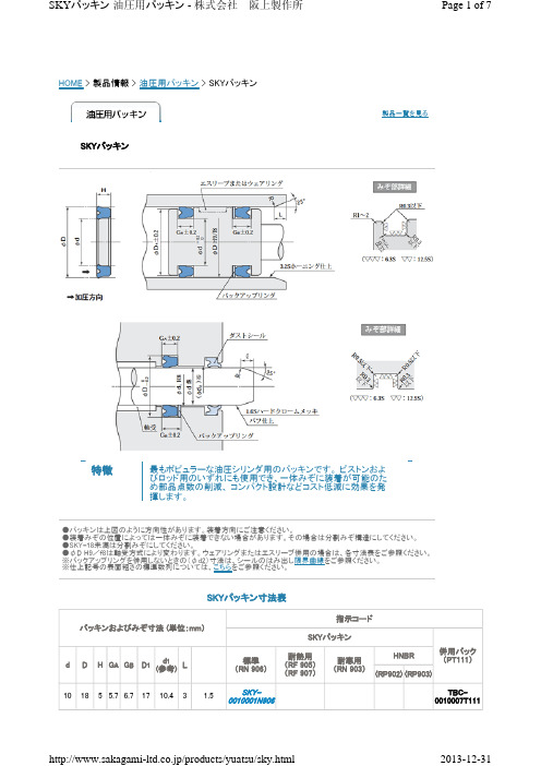
HOME > 製品情報 > 油圧用パッキン > SKYパッキン製品一覧を見る特徴SKYパッキン最もポピュラーな油圧シリンダ用のパッキンです。
ピストンおよびロッド用のいずれにも使用でき、一体みぞに装着が可能のため部品点数の削減、 コンパクト設計などコスト低減に効果を発揮します。
●パッキンは上図のように方向性があります。
装着方向にご注意ください。
●装着みぞの位置によっては一体みぞに装着できない場合があります。
その場合は分割みぞ構造にしてください。
●SKY-18未満は分割みぞにしてください。
●φD H9/f8は軸受方式により変わります。
ウェアリングまたはエスリーブ併用の場合は、各寸法表をご参照ください。
※バックアップリングを併用しないときの(φd2)寸法は、シールのはみ出し限界曲線をご参照ください。
※仕上記号の表面粗さの標準数列については、こちらをご参照ください。
SKYパッキン寸法表パッキンおよびみぞ寸法 (単位:mm)指示コードSKYパッキン併用バック (PT111)dDH G A G B D 1d 1 (参考)L標準 (RN 906)耐熱用 (RF 905) (RF 907)耐寒用 (RN 903)HNBR (RP902)(RP903)10185 5.7 6.71710.431.5SKY- 0010001N906TBC- 0010007T111パッキンおよびみぞ寸法 (単位:mm)指示コードSKYパッキン併用バック (PT111)dDH G A G B D 1d 1 (参考)L標準 (RN 906)耐熱用 (RF 905) (RF 907)耐寒用 (RN 903)HNBR (RP902)(RP903)12205 5.7 6.71912.43 1.5SKY- 0012001N906 TBC- 0012003T11112.5205 5.7 6.71912.93 1.5SKY-12.5TCS- 20×12.514225 5.7 6.72114.43 1.5SKY-14SKY-14F●●TCS- 22×1416245 5.7 6.72316.43 1.5SKY-16SKY-16F● TCS- 24×1617255 5.7 6.72417.43 1.5SKY- 0017001N906TCS- 25×1718265 5.7 6.72518.43 1.5SKY-18SKY-18F● TCS- 26×1820285 5.7 6.72720.43 1.5SKY-20SKY-20FSKY-20NTCS- 28×202030678.52920.43 1.5SKY- 0020001N906TBC- 0020006T11122305 5.7 6.72922.43 1.5SKY-22SKY-22F ●●TCS- 30×2222.4305 5.7 6.72922.83 1.5SKY-22.4SKY-22.4F ●●TCS- 30×22.423.531.55 5.7 6.730.523.93 1.5SKY-23.5SKY-23.5FTCS- 31.5×23.524325 5.7 6.73124.43 1.5SKY- 0024002N906TCS- 32×2425335 5.7 6.73225.43 1.5SKY-25SKY-25FSKY-25NTCS- 33×2526345 5.7 6.73326.43 1.5SKY- 0026001N906 TBC- 0026005T11127355 5.7 6.73427.43 1.5SKY- 0027001N906TCS- 35×272835.55 5.7 6.734.528.43 1.5SKY-28SKY-28FSKY-28N●●TCS- 35.5×2828365 5.7 6.73528.431.5SKY-28ATCS- 36×2830385 5.7 6.73730.5 3.53SKY- 0030001N906TBC- 0030005T1113040678.53930.5 3.53SKY-30SKY-30F SKY-30NTCS- 40×3031.541.5678.540.5323.53SKY-31.5SKY-31.5FTCS- 41.5×31.53242678.54132.5 3.53SKY-32TCS- 42×323545678.54435.5 3.53SKY-35SKY-35FSKY-35NTCS- 45×35併用バック (PT111)dDH G A G B D 1d 1 (参考)L標準 (RN 906)耐熱用 (RF 905) (RF 907)耐寒用 (RN 903)HNBR (RP902)(RP903)35.545678.54436 3.53SKY-35.5SKY-35.5FSKY-35.5N●●TCS- 45×35.535.545.5678.544.5363.53SKY-35.5A TCS- 45.5×35.53646678.54536.5 3.53SKY-36SKY-36F●TCS- 46×363848678.54738.5 3.53SKY- 0038001N906TBC- 0038003T1114050678.54940.5 3.53SKY-40SKY-40F SKY-40N TCS- 50×404555678.55445.5 3.53SKY-45SKY-45F SKY-45N TCS- 55×454556789.55545.5 3.53SKY-45A SKY-45AF SKY-45AN ●●TCS- 56×455060678.55950.5 3.53SKY-50SKY-50F SKY-50NTCS- 60×505363678.56253.6 3.53SKY-53SKY-53FTCS- 63×535565678.56455.6 3.53SKY-55SKY-55F SKY-55NTCS- 65×555666678.56556.6 3.53SKY-56SKY-56F●●TCS- 66×565868678.56758.6 3.53SKY- 0058001N906TBC- 0058004T1116070678.56960.6 3.53SKY-60SKY-60F SKY-60NTCS- 70×606071789.57060.6 3.53SKY-60ASKY-60AFTCS- 71×606171678.57061.6 3.53SKY- 0061001N906TC-パッキン 指示コード6373678.57263.6 3.53SKY-63SKY-63F SKY-63N ●TCS- 73×636575678.57465.6 3.53SKY-65SKY-65F SKY-65NTCS- 75×656777678.57667.6 3.53SKY-67SKY-67F●●TCS- 77×677080678.57970.6 3.53SKY-70SKY-70F SKY-70N●●TCS- 80×707180678.57971.6 3.53SKY-71SKY-71F●TCS- 80×717585678.58475.6 3.53SKY-75SKY-75F SKY-75N TCS- 85×758090678.58980.6 3.53SKY-80SKY-80FSKY-80N●●TCS- 90×80併用バック (PT111)dDH G A G B D 1d 1 (参考)L標準 (RN 906)耐熱用 (RF 905) (RF 907)耐寒用 (RN 903)HNBR (RP902)(RP903)8595678.59485.6 3.53SKY- 0085002N906TBC- 0085001T11185100910129885.644SKY-85SKY-85FSKY-85N●●TCS- 100×85861008.59.511.59886.644SKY-86SKY-86FTCS- 100×86891049101210289.644SKY- 0089001N906 TBC- 0089001T11190100678.59990.644SKY- 0090001N906TBC- 0090013T111901059101210390.644SKY-90SKY-90F SKY-90N●TCS- 105×90951109101210895.644SKY-95SKY-95FTCS- 110×95961119101210996.644SKY- 0096001N906TBC- 0096001T111981128.59.511.511098.644SKY-98SKY-98FTCS- 112×9810011591012113100.644SKY-100SKY-100FSKY-100N●●TCS- 115×10010512091012118105.644SKY- 0105002N906TBC- 0105001T1111061208.59.511.5118106.644SKY-106SKY-106FSKY-106NTCS- 120×10611012591012123110.644SKY- 0110003N906●●TBC- 0110001T1111121258.59.511.5123112.644SKY-112SKY-112F TCS- 125×11211212591012123112.644SKY-112ASKY-112AF●●TCS- 125×1121151308.59.511.5128115.644SKY- 0115002N906SKY- 0115001N903 TBC- 0115002T1111181328.59.511.5130118.644SKY-118SKY-118FSKY-118NTCS- 132×1181191338.59.511.5131119.644SKY- 0119001N906 TBC- 0119001T11112013591012133120.644SKY- 0120002N906TBC- 0120001T11112514091012138125.644SKY-125SKY-125FSKY-125N●●TCS- 140×12513014591012143130.644SKY- 0130001N906TBC- 0130001T1111321458.59.511.5143132.644SKY-132SKY-132FTCS- 145×132併用バック (PT111)dDH G A G B D 1d 1 (参考)L標準 (RN 906)耐熱用 (RF 905) (RF 907)耐寒用 (RN 903)HNBR (RP902)(RP903)1361508.59.511.5148136.644SKY-136SKY-136F TCS- 150×13614015591012153140.644SKY-140SKY-140F●●TCS- 155×14014516091012158145.644SKY-145SKY-145F SKY-145NTCS- 160×14515016591012163150.644SKY-150SKY-150F TCS- 165×15015517091012168155.644SKY-155SKY-155F TCS- 170×15516017591012173160.644SKY-160SKY-160F ●●TCS- 175×16016518091012178165.644SKY-165SKY-165FTCS- 180×16517018591012183170.644SKY- 0170001N906TBC- 0170001T11117519091012188175.644SKY-175SKY-175F TCS- 190×175180200121315.5198180.855SKY-180SKY-180F●●TCS- 200×180185205121315.5203185.855SKY- 0185001N906TBC- 0185001T111190*********.5208190.855SKY- 0190003N906SKY- 0190001F905 TBC- 0190004T111195215121315.5213195.855SKY- 0195001N906TBC- 0195006T111200*********.5218200.855SKY-200SKY-200F TCS- 220×200204224121315.5222204.855SKY-204SKY-204FTCS- 224×204210230121315.5228210.855SKY- 0210002N906SKY- 0210001F905 TBC- 0210004T111215235121315.5233215.855SKY- 0215001N906 TBC- 0215003T111220*********.5238220.855SKY- 0220001N906TBC- 0220003T111224244121315.5242224.855SKY-224SKY-224F TCS- 244×224230*********.5248230.855SKY-230SKY-230FTCS- 250×230235255121315.5253235.855SKY- 0235001N906 TBC- 0235001T111237257121315.5255237.855SKY- 0237001N906TC-パッキン 指示コード併用バック (PT111)dDH G A G B D 1d 1 (参考)L標準 (RN 906)耐熱用 (RF 905) (RF 907)耐寒用 (RN 903)HNBR (RP902)(RP903)240260121315.5258240.855SKY- 0240003N906SKY- 0240001F905 TBC- 0240001T111245265121315.5263245.855SKY- 0245001N906TBC- 0245004T111250*********.5268250.855SKY-250SKY-250FTCS- 270×250260280141518278260.855SKY-260SKY-260F TCS- 280×260280300141518298280.855SKY-280SKY-280FTCS- 300×280290310141518308290.855SKY- 0290001N906TBC- 0290001T111295315141518313295.855SKY-295SKY-295FTCS- 315×295300320121316318300.855SKY- 0300003N906 TBC- 0300003T11131033014151832831155SKY- 0310001N906 TBC- 0310002T11131533514151833331655SKY-315 TCS- 335×31533535514151835333655SKY-335 TCS- 355×33535537514151837335655SKY-355TCS- 375×35538040014151839838155SKY-380SKY-380FTCS- 400×38040042014151841840155SKY-400 TCS- 420×40043045014151844843155SKY-430 TCS- 450×43045047014151846845155SKY-450 TCS- 470×45048050014151849848155SKY-480 TCS- 500×48050052517182152250155SKY- 0500001N906 TBC- 0500002T11154056014151855854155SKY- 0540001N906 TBC- 0540001T11155057013141756855155SKY- 0550001N906 TBC- 0550001T11161063014151862861155SKY- 0610001N906 TBC- 0610001T11163065517182165263155SKY- 0630001N906TBC- 0630001T111併用バック (PT111)dDH G A G B D 1d 1 (参考)L標準 (RN 906)耐熱用 (RF 905) (RF 907)耐寒用 (RN 903)HNBR (RP902)(RP903)66069018192268766155SKY- 0660001N906 TC-パッキン 指示コード77080018192279777155SKY- 0770001N906TC-パッキン 指示コード≪2012年5月 更新≫★ご注文・お問い合わせは、指示コードにてご指示ください。
AGMA Standards-美国齿轮标准
AGMA 217.01AGMA 900-H06AGMA 901-A92AGMA 904-C96AGMA 908-B89AGMA 910-C90AGMA 911-A94AGMA 912-A04AGMA 913-A98AGMA 914-B04AGMA 915-1-A02AGMA 915-2-A05AGMA 915-3-A99-1999AGMA 917-B97AGMA 918-A93AGMA 920-A01AGMA 922-A96AGMA 923-B05AGMA 925-A03AGMA 926-C99-1999AGMA 927-A01AGMA 930-A05AGMA 931-A02AGMA 932-A05AGMA 933-B03AGMA 935-A05AGMA 938-A05AGMA ISO 10064-1AGMA ISO 10064-2AGMA ISO 10064-5-A06 AGMA ISO 14179-1ANSI/AGMA 1003-G93 (R1999) ANSI/AGMA 1006-A97 (R2003) ANSI/AGMA 1010-E95 (R2004) ANSI/AGMA 1012-2005ANSI/AGMA 1102-A03ANSI/AGMA 1106-A97 (R2003) ANSI/AGMA 2000-A88ANSI/AGMA 2001-D04ANSI/AGMA 2002-B88 (R1996) ANSI/AGMA 2003-B97 (R2003) ANSI/AGMA 2004-B89 (R2006) ANSI/AGMA 2005-D03ANSI/AGMA 2007-C00ANSI/AGMA 2008-C01ANSI/AGMA 2009-B01ANSI/AGMA 2011-A98ANSI/AGMA 2015-1-A01ANSI/AGMA 2015-2-A06ANSI/AGMA 2101-D04ANSI/AGMA 2111-A98ANSI/AGMA 2116-A05ANSI/AGMA 6000-B96 (R2002) ANSI/AGMA 6001-D97 (R2003) ANSI/AGMA 6002-B93 (R2001) ANSI/AGMA 6004-F88 (R1996)ANSI/AGMA 6005-B89 (R1996) ANSI/AGMA 6008-A98ANSI/AGMA 6011-I03ANSI/AGMA 6013-A06ANSI/AGMA 6022-C93 (R2000) ANSI/AGMA 6023-A88 (R2000) ANSI/AGMA 6025-D98ANSI/AGMA 6033-B98ANSI/AGMA 6034-B92 (R1999) ANSI/AGMA 6035-2002ANSI/AGMA 6113-A06ANSI/AGMA 6123-A06ANSI/AGMA 6133-B98ANSI/AGMA 6135-2002ANSI/AGMA 9000-C90 (R2001) ANSI/AGMA 9001-B97 (R2003) ANSI/AGMA 9002-B04ANSI/AGMA 9003-A91 (R1999) ANSI/AGMA 9004-A99ANSI/AGMA 9005-E02ANSI/AGMA 9008-B00 (R2006) ANSI/AGMA 9009-D02ANSI/AGMA 9112-A04ANSI/AGMA ISO 1328-1ANSI/AGMA ISO 1328-2ANSI/AGMA ISO 18653-A06ANSI/AGMA/AWEA 6006-A03 Supplemental Tables for AGMA 2015 AGMA 6006-A03ANSI/AGMA 6009-A00ANSI/AGMA 6109-A00ANSI/AGMA 6110-F97 (R2003)Information Sheet - Gear Scoring Design for Aerospace Spur and Helical Power GearsStyle Manual for the Preparation of Standards, Information Sheets and Editorial ManualsA Rational Procedure for the Preliminary Design of Minimum Volume GearsMetric UsageInformation Sheet - Geometry Factors for Determining the Pitting Resistance and Bending Strength of Spur, HelicFormats for Fine-Pitch Gear Specification DataDesign Guidelines for Aerospace GearingMechanisms of Gear Tooth FailureMethod for Specifying the Geometry of Spur and Helical GearsGear Sound Manual - Part I: Fundamentals of Sound as Related to Gears; Part II: Sources, Specifications and Levels of G Inspection Practices - Part 1: Cylindrical Gears - Tangential MeasurementsInspection Practices - Part 2: Cylindrical Gears - Radial MeasurementsInspection Practices - Gear Blanks, Shaft Center Distance and Parallelism"Design Manual for Parallel Shaft Fine-Pitch GearingA Summary of Numerical Examples Demonstrating the Procedures for Calculating Geometry Factors for Spur an Materials for Plastic GearsLoad Classification and Service Factors for Flexible CouplingsMetallurgical Specifications for Steel GearingEffect of Lubrication on Gear Surface DistressRecommended Practice for Carburized Aerospace GearingLoad Distribution Factors - Analytical Methods for Cylindrical GearsCalculated Bending Load Capacity of Powder Metallurgy (P/M) External Spur GearsCalibration of Gear Measuring Instruments and Their Application to the Inspection of Product GearsRating the Pitting Resistance and Bending Strength of Hypoid GearsBasic Gear GeometryRecommendations Relative to the Evaluation of Radial Composite Gear Double Flank TestersShot Peening of GearsCylindrical Gears - Code of Inspection Practice - Part 1: Inspection of Corresponding Flanks of Gear TeethCylindrical Gears - Code of Inspection Practice - Part 2: Inspection Related to Radial Composite Deviations, Runout, Tooth Code of Inspection Practice - Part 5: Recommendations Relative to Evaluation of Gear Measuring InstrumentsGear Reducers - Thermal Capacity Based on ISO/TR 14179-1Tooth Proportions for Fine-Pitch Spur and Helical GearingTooth Proportions for Plastic GearsAppearance of Gear Teeth - Terminology of Wear and FailureGear Nomenclature, Definitions of Terms with SymbolsTolerance Specification for Gear HobsTooth Proportions for Plastic Gears (Metric Version of ANSI/AGMA 1006-A97)Gear Classification and Inspection Handbook - Tolerances and Measuring Methods for Unassembled Spur and H Fundamental Rating Factors and Calculation Methods for Involute Spur and Helical Gear TeethTooth Thickness Specification and MeasurementRating the Pitting Resistance and Bending Strength of Generated Straight Bevel, Zerol Bevel and Spiral Bevel Gear Teeth Gear Materials and Heat Treatment ManualDesign Manual for Bevel GearsGears - Surface Temper Etch Inspection After GrindingAssembling Bevel GearsBevel Gear Classification, Tolerances and Measuring MethodsCylindrical Wormgearing Tolerance and Inspection MethodsAccuracy Classification System - Tangential Measurements for Cylindrical GearsAccuracy Classification System - Radial Measurements for Cylindrical GearsFundamental Rating Factors and Calculation Methods for Involute Spur and Helical Gear Teeth (Metric Edition) Cylindrical Wormgearing Tolerance and Inspection Methods (Metric)Evaluation of Double Flank Testers for Radial Composite Measurement of GearsSpecification for Measurement of Linear Vibration on Gear UnitsDesign and Selection of Components for Enclosed Gear DrivesDesign Guide for Vehicle Spur and Helical GearsGear Power Rating for Cylindrical Grinding Mills, Kilns, Coolers, and DryersPower Rating for Helical and Herringbone Gearing for Rolling Mill ServiceSpecifications for Powder Metallurgy GearsSpecification for High Speed Helical Gear UnitsStandard for Industrial Enclosed Gear DrivesDesign Manual for Cylindrical WormgearingDesign Manual for Enclosed Epicylic Gear DrivesSound for Enclosed Helical, Herringbone, and Spiral Bevel Gear DrivesMarine Propulsion Gear Units, Part 1 - MaterialsPractice for Enclosed Cylindrical Wormgear Speed Reducers and GearmotorsDesign, Rating and Application of Industrial Globoidal WormgearingStandard for Industrial Enclosed Gear Drives (Metric Edition)Design Manual for Enclosed Epicyclic Gear DrivesMaterials for Marine Propulsion GearingDesign, Rating and Application of Industrial Globoidal Wormgearing (Metric Edition)Flexible Couplings - Potential Unbalance ClassificationFlexible Couplings - LubricationBores and Keyways for Flexible Couplings (Inch Series)Flexible Couplings - Keyless FitsFlexible Couplings - Mass Elastic Properties and Other CharacteristicsIndustrial Gear LubricationFlexible Couplings - Gear Type - Flange Dimensions, Inch Series (Also listed as 9008-B99)Flexible Couplings - Nomenclature for Flexible CouplingsBores and Keyways for Flexible Couplings (Metric Series)Cylindrical Gears - ISO System of Accuracy - Part 1: Definitions and Allowable Values of Deviations Relevant to Correspon Cylindrical Gears - ISO System of Accuracy - Part 2: Definitions and Allowable Values of Deviations Relevant to Radial Co Gears - Evaluation of Instruments for the Measurement of Individual GearsDesign and Specification of Gearboxes for Wind TurbinesAccuracy Classification System - Tangential Measurement Tolerance Tables for Cylindrical GearsStandard for Design and specification of Gearbox for Wind Turbines (Spersedes AGMA 921 - A97)Standard for Gearmotor, Shaft Mounted and Screw Conveyor DrivesStandard for Gearmotor, Shaft Mounted and Screw Conveyor Drives (metric version)Spur, Helical, Herringbone, and Bevel Enclosed DrivesAGMA Technical CommitteeAGMA Technical CommitteeAGMA Technical CommitteeAGMA Technical CommitteeAGMA Technical CommitteeAGMA Technical Committeecifications and Levels of Gear Sound; Part III: Gear Noise ControlAGMA Technical CommitteeAGMA Technical CommitteeDeviations, Runout, Tooth Thickness and BacklashInstrumentsAGMAAGMASpiral Bevel Gear TeethAGMAAGMAAGMAMetric Edition)AGMAAGMAAGMAAGMAAGMAAGMAAGMAns Relevant to Corresponding Flanks of Gear Teethns Relevant to Radial Composite Deviations and Runout Information in GE libraries while not listed herelisted in sheet ver3 while missed in ver4listed in sheet ver3 while missed in ver4listed in sheet ver3 while missed in ver4AGMA+217.01.pdf46 AGMA+900-H06.pdf30 AGMA+901-A92.pdf42 AGMA+904-C96.pdf42 AGMA+908-B89.pdf84 AGMA+910-C90.pdf51 AGMA+911-A94.pdf96 AGMA+912-A04.pdf70 AGMA+913-A98.pdf58 AGMA+914-B04.pdf76 AGMA+915-1-A02.pdf105 AGMA+915-2-A05.pdf47 AGMA+915-3-A99-1999.pdf42 AGMA+917-B97+.pdf84 AGMA+918-A93.pdf68 AGMA+920-A01.pdf58 AGMA+922-A96.pdf42 AGMA+923-B05.pdf79 AGMA+925-A03.pdf69 AGMA+926-C99-1999.pdf48 AGMA+927-A01.pdf69 AGMA+930-A05.pdf83 AGMA+931-A02.pdf63 AGMA+932-A05.pdf60 AGMA+933-B03.pdf37 AGMA+935-A05.pdf40 AGMA+938-A05.pdf45 AGMA+ISO+10064-1.pdf75 AGMA+ISO+10064-2.pdf55 AGMA+ISO+10064-5-A06.pdf145 AGMA+ISO+14179-1.pdf69 ANSI+AGMA+1003-G93+(R1999).pdf68 ANSI+AGMA+1006-A97+(R2003).pdf68 ANSI+AGMA+1010-E95+(R2004).pdf96 ANSI+AGMA+1012-2005.pdf82 ANSI+AGMA+1102-A03.pdf82 ANSI+AGMA+1106-A97+(R2003).pdf62 ANSI+AGMA+2000-A88.pdf140 ANSI+AGMA+2001-D04.pdf167 ANSI+AGMA+2002-B88+(R1996).pdf90 ANSI+AGMA+2003-B97+(R2003).pdf145 ANSI+AGMA+2004-B89+(R2006).pdf96 ANSI+AGMA+2005-D03.pdf167 ANSI+AGMA+2007-C00.pdf37 ANSI+AGMA+2008-C01.pdf68 ANSI+AGMA+2009-B01.pdf101 ANSI+AGMA+2011-A98.pdf84 ANSI+AGMA+2015-1-A01.pdf84 ANSI+AGMA+2015-2-A06.pdf40 ANSI+AGMA+2101-D04.pdf140 ANSI+AGMA+2111-A98.pdf74 ANSI+AGMA+2116-A05.pdf38 ANSI+AGMA+6000-B96+(R2002).pdf73 ANSI+AGMA+6001-D97+(R2003).pdf84 ANSI+AGMA+6002-B93+(R2001).pdf68 ANSI+AGMA+6004-F88+(R1996).pdf84ANSI+AGMA+6005-B89+(R1996).pdf79 ANSI+AGMA+6008-A98.pdf56 ANSI+AGMA+6011-I03.pdf95 ANSI+AGMA+6013-A06.pdf159 ANSI+AGMA+6022-C93+(R2000).pdf73 ANSI+AGMA+6023-A88+(R2000).pdf84 ANSI+AGMA+6025-D98.pdf79 ANSI+AGMA+6033-B98.pdf84 ANSI+AGMA+6034-B92+(R1999).pdf56 ANSI+AGMA+6035-2002.pdf79 ANSI+AGMA+6113-A06.pdf135 ANSI+AGMA+6123-A06.pdf140 ANSI+AGMA+6133-B98.pdf74 ANSI+AGMA+6135-2002.pdf74 ANSI+AGMA+9000-C90+(R2001).pdf62 ANSI+AGMA+9001-B97+(R2003).pdf42 ANSI+AGMA+9002-B04.pdf55 ANSI+AGMA+9003-A91+(R1999).pdf51 ANSI+AGMA+9004-A99.pdf69 ANSI+AGMA+9005-E02.pdf84 ANSI+AGMA+9008-B00+(R2006).pdf38 ANSI+AGMA+9009-D02.pdf49 ANSI+AGMA+9112-A04.pdf53 ANSI+AGMA+ISO+1328-1.pdf63 ANSI+AGMA+ISO+1328-2.pdf42 ANSI+AGMA+ISO+18653-A06.pdf75 ANSI+AGMA+AWEA+6006-A03.pdf208 Supplemental+Tables+for+AGMA+20137。
通用日产大众丰田汽车电子电磁兼容标准与项目
静电放电抗扰度测试EQ/IR03
静电放电抗扰度测试EQ/IR04
手持式收发机抗扰度测试EQ/IR05
传导瞬态骚扰测试EQ/MC01
传导骚扰电流测试EQ/MC02
传导骚扰测试EQ/MC03
辐射骚扰测试EQ/MR01
磁场骚扰测试EQ/MR02
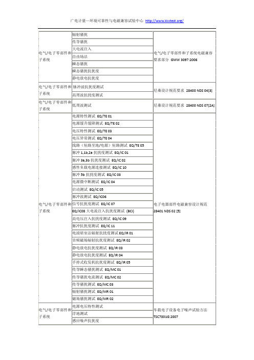
电气/电子零部件和子系统
电源电压特性测试
电气/电子零部件和子系统
辐射骚扰
电气/电子零部件和子系统电磁兼容要求部分GMW3097:2006
传导骚扰
大电流注入
自由场法
瞬态骚扰
瞬态骚扰抗扰度
静电放电抗扰度
电气/电子零部件和子系统
脉冲波抗扰度测试
尼桑设计规范要求28400 NDS 04[3]
高周波抗扰度测试
电气/电子零部件和子系统
低周波测试
尼桑设计规范要求28400 NDS 07[2A]
反极性测试
过压测试
电源微中断测试
电压跌落恢复测试
叠加正弦波电压测试
叠加脉冲波电压测试
间断性内部短接电源/地测试
连续短路至电源/地测试
内部地短路电源测试
单线短时开路测试
多路间断开路测试
接地偏移测试
电源偏移测试
叠加数字波电压测试
过载测试
过载保险丝保护测试
绝缘电压测试
电气/电子零部件和子系统
E-01长时间过电压
对需要获得认可的车载零部件的电磁辐射骚扰测试方法TSC7026G:2008
电气/电子零部件和子系统
辐射骚扰
汽车电子零部件电磁干扰抑制测试方法TSC7508G:2008
电气/电子零部件和子系统
传导骚扰-电压法
KUTAI ADVR-08 Universal Hybrid Analog-Digital Volt

KUTAI ELECTRONICS INDUSTRY CO., LTD.TEL : +886-7-8121771FAX : +886-7-8121775Website : Headquarters : No.3, Lane 201, Chien Fu St., Chyan Jenn Dist., Kaohsiung 80664, TAIWANADVR-08Universal Hybrid Analog-Digital Voltage Regulator Operation ManualAn Universal Hybrid Analog/Digital 2 lines sensing 8 Amp AVR with multiple power input capability such as Full Harmonic (Compound Windings), Harmonic + Auxiliary Winding, PMG and SHUNT.Compatible with Leroy Somer* R438, R448, R449 and more.Use with KUTAI IVT-1260 / IVT-2460 add-on module can boost generator motor starting capacity.SECTION 1 : SPECIFICATIONSensing Input (E1, E2) Static Power DissipationVoltage 110 - 480 Vac, 1 phase Max.6 watts90 - 130 Vac @ 110 Vac180 - 260 Vac @ 220 Vac Burden in SHUNT & PMG Wiring340 - 520 Vac @ 380 Vac 880 VA @ power input 110 Vac Frequency 50/60 Hz, DIP switch setting 1760 VA @ power input 220 VacPower Input (X1, X2, Aux1)Quadrature Droop Input (S1, S2, S3)Voltage 40 - 300 Vac, 1 phase / 3 phase CT 5A (S1-S2) or 1A (S2-S3) greater than 5VA Frequency 50 - 500 Hz Max. +/- 5% @ P.F +/- 0.71 phase (X1、X2) / 3 phase (X1、X2、Aux1)Analogue Voltage Input (A1, A2)Auxiliary Input (Aux1, Aux2)Input resistance greater than 2K ohmsVoltage 40 - 300 Vac, 1 phase Max. Input +/- 5 VdcFrequency 50 - 500 Hz Sensitivity +/- 25% Generator Volts (adjustable)Excitation Output (F+, F-)Under Frequency Protection (Factory Presets) Voltage Max. 63 Vdc @ power input 110 Vac 50 Hz system presets knee point at 45 HzMax. 125 Vdc @ power input 220 Vac 60 Hz system presets knee point at 55 Hz Current Continuous 8AIntermittent 12A for 10 secs. Over Excitation ProtectionResistance ≧8 ohms @ power input 110 Vac Set point 170 Vdc +/- 5 % @ power input 220 Vac ≧16 ohms @ power input 220 VacFuse Spec. Slow blow 5 x 20mm S505-10A Voltage Thermal DriftLess than 3% at temperature range -40 to +70 ˚C External Voltage Adjustment (VR1, VR2)Max. +/- 4% @ 500 ohms 1 watt potentiometer Under-Frequency Knee Point Thermal DriftMax. +/- 8% @ 1K ohm 1 watt potentiometer Less than +/- 0.1 Hz at -40 to +70 ˚CVoltage Regulation EnvironmentLess than +/- 0.5% ( with 4% engine governing ) Operating T emperature -40 to +70 ˚CStorage T emperature -40 to +85 ˚CBuild Up Voltage Relative Humidity Max. 95%6 Vac 25 Hz residual volts at power input terminal Vibration 3 Gs @ 100 - 2K HzSoft Start Ramp Time Dimensions4 seconds +/- 10% 171.0 (L) x 120.0 (W) x 50.0 (H) mmTypical System Response WeightLess than 20 milliseconds 820 g +/- 2%EMI SuppressionInternal electromagnetic interference filtering___________________________________________________________________________________________ 2ADVR-08SECTION 2 : OUTLINE / SIZE / INSTALLATION REFERENCEFlag Terminal (“Fast-On” terminal)Figure 1Outline Drawing___________________________________________________________________________________________ ADVR-08 3___________________________________________________________________________________________ 4ADVR-08SECTION 3 : DIP SWITCH PROGRAMMING & VR ADJUSTMENTSU/F LEDO/E LEDSet fully50 Hz System : 40 to 51 Hz (Lowest position)60 Hz System : 50 to 61 Hz (Lowest position)(See TRIM)This adjustment allows some control over the generator voltage dip when applying load.It is typically used to compensate for turbo lag, leaving the generator to operate below the UFRO knee point setting. The voltage droop ratio can be set using the DIP adjustment. The range is 10 to 3 V/Hz.HZ HZ___________________________________________________________________________________________ ADVR-085SECTION 4 : WIRING CONNECTIONSExciter fieldPMGS2-S3 N:1AS 2-S 3 N :1AS 1-S 2 N :5A C.T Stator windingsS2-S3 N:1AS1-S2 N:5A Exciter fieldS2-S3 N:1AS1-S2 N:5A C.TFigure 2 Single & Three Phase PMGFigure 3 Three Phase AuxiliaryWinding (Full Harmonic)Figure 4 Auxiliary & HarmonicFigure 5 Self-Excited (SHUNT)Exciter fieldFigure 6ADVR-08 & IVT-1260 / IVT-2460 Wiring Connection※Use only the replacement fuses specified in this user manual.※Appearance and specifications of products are subject to change for improvement without prior notice.___________________________________________________________________________________________ 6ADVR-08。
汽车检测故障码大全

汽车检测故障码大全00000 没有查询到任何故障00001 制动器控制单元00002 变速器控制单元00003 控制单元00224 碟型天线需要重新校准00237 ABS 电磁阀: 左前( N59 ) 00238 ABS 电磁阀: 右前( N58 )00239 ABS 电磁阀:左后( N57 ) 00240 ABS 电磁阀: 右后( N56 )00241 驱动防滑压力调节阀( N238 )00242 发动机节气门阀( N237 )00243 发动机制动器00244 ABS 阀供给电压:右前+左后00245 ABS 阀供给电压: 左前+右后00246 ABS 阀接地:右前+左后00247 ABS 阀接地: 左前+右后00248 变速器开关( E206 )00250 分动器开关( E207 )00254 驱动防滑调节错误00255 ABS 电磁阀00257 ABS 进油阀:左前( N101 )00258 电磁阀1:( N88 )00259 ABS 进油阀: 右前( N99 )00260 电磁阀2:( N89 )00261 进油阀: ABS后部( N103 )00262 电磁阀3: ( N90 )00263 变速器00264 电磁阀4: ( N91 )00265 ABS 出油阀:左前( N102 ) 00266 电磁阀5: ( N92 )00267 ABS 出油阀: 右前( N100 )00268 电磁阀6: ( N93 )00269 ABS 出油阀:后部( N104 )00270 电磁阀7: ( N94 )00271 参见维修组100273 ABS 进油阀:右后( N133 ) 00274 ABS 进油阀:左后( N134 )00275 ABS 出油阀: 右后( N135 ) 00276 ABS 出油阀: 左后( N136 )00277 ABS 进油阀/出油阀: 左前( N137 ) 00278 ABS 主阀:( N105 )00279 差速锁阀—1—: ( N125 )00280 差速锁阀—2—: ( N126 )00281 车速传感器( G68 )00282 节气门位置调节器( V60 )00283 ABS 转速传感器:左前( G47 )00284 ABS 进油阀/出油阀:右前( N138 )00285 ABS 转速传感器:右前( G45 )00286 ABS 进油阀/出油阀:左后( N139 )00287 ABS 转速传感器: 右前( G44 )00289 ABS 进油阀/出油阀:右后( N140 )00290 ABS 转速传感器:右前( G46 )00291 ABS 压力警报开关/液面报警开关( F116/F117 )00292 液压供给压力油位00293 多功能开关( F125 )00294 变速器压力状态开关1( F174 )00295 变速器压力状态开关2( F175 )00296 强制低档开关( F8 )00297 变速器转速传感器( G38 )00298 后桥差速锁开关( E121 )00299 变速器换档范围程序开关( E122 )00300 变速器油温度传感器( G93 )00301 ABS 回流泵( V39 )00302 ABS 电磁阀继电器( J106 )00303 功能选择器开关( E91 )00305 燃油消耗指示信号00306 二次空气喷射缸体左侧00307 二次空气喷射缸体右侧00309 洗涤液计量泵( V135 )00310 催化转换器温度传感器 1 ( G20 ) 00312 催化转换器温度传感器 2 ( G132 ) 00313 催化转换器00314 废气内部循环双路阀( N161 )00347 电磁阀800348 电磁阀900349 电磁阀1000350 Mass Recirc。
Indradrive 系列 故障代码
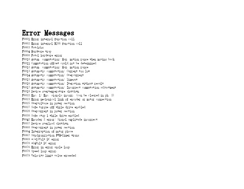
Error MessagesF9001 Error internal function call.F9002 Error internal RTOS function callF9003 WatchdogF9004 Hardware trapF8000 Fatal hardware errorF8010 Autom. commutation: Max. motion range when moving back F8011 Commutation offset could not be determinedF8012 Autom. commutation: Max. motion rangeF8013 Automatic commutation: Current too lowF8014 Automatic commutation: OvercurrentF8015 Automatic commutation: TimeoutF8016 Automatic commutation: Iteration without resultF8017 Automatic commutation: Incorrect commutation adjustment F8018 Device overtemperature shutdownF8022 Enc. 1: Enc. signals incorr. (can be cleared in ph. 2) F8023 Error mechanical link of encoder or motor connectionF8025 Overvoltage in power sectionF8027 Safe torque off while drive enabledF8028 Overcurrent in power sectionF8030 Safe stop 1 while drive enabledF8042 Encoder 2 error: Signal amplitude incorrectF8057 Device overload shutdownF8060 Overcurrent in power sectionF8064 Interruption of motor phaseF8067 Synchronization PWM-Timer wrongF8069 +/-15Volt DC errorF8070 +24Volt DC errorF8076 Error in error angle loopF8078 Speed loop error.F8079 Velocity limit value exceededF8091 Power section defectiveF8100 Error when initializing the parameter handlingF8102 Error when initializing power sectionF8118 Invalid power section/firmware combinationF8120 Invalid control section/firmware combinationF8122 Control section defectiveF8129 Incorrect optional module firmwareF8130 Firmware of option 2 of safety technology defectiveF8133 Error when checking interrupting circuitsF8134 SBS: Fatal errorF8135 SMD: Velocity exceededF8140 Fatal CCD error.F8201 Safety command for basic initialization incorrectF8203 Safety technology configuration parameter invalidF8813 Connection error mains chokeF8830 Power section errorF8838 Overcurrent external braking resistorF7010 Safely-limited increment exceededF7011 Safely-monitored position, exceeded in pos. DirectionF7012 Safely-monitored position, exceeded in neg. DirectionF7013 Safely-limited speed exceededF7020 Safe maximum speed exceededF7021 Safely-limited position exceededF7030 Position window Safe stop 2 exceededF7031 Incorrect direction of motionF7040 Validation error parameterized - effective thresholdF7041 Actual position value validation errorF7042 Validation error of safe operation modeF7043 Error of output stage interlockF7050 Time for stopping process exceeded8.3.15 F7051 Safely-monitored deceleration exceeded (159)8.4 Travel Range Errors (F6xxx) (161)8.4.1 Behavior in the Case of Travel Range Errors (161)8.4.2 F6010 PLC Runtime Error (162)8.4.3 F6024 Maximum braking time exceeded (163)8.4.4 F6028 Position limit value exceeded (overflow) (164)8.4.5 F6029 Positive position limit exceeded (164)8.4.6 F6030 Negative position limit exceeded (165)8.4.7 F6034 Emergency-Stop (166)8.4.8 F6042 Both travel range limit switches activated (167)8.4.9 F6043 Positive travel range limit switch activated (167)8.4.10 F6044 Negative travel range limit switch activated (168)8.4.11 F6140 CCD slave error (emergency halt) (169)8.5 Interface Errors (F4xxx) (169)8.5.1 Behavior in the Case of Interface Errors (169)8.5.2 F4001 Sync telegram failure (170)8.5.3 F4002 RTD telegram failure (171)8.5.4 F4003 Invalid communication phase shutdown (172)8.5.5 F4004 Error during phase progression (172)8.5.6 F4005 Error during phase regression (173)8.5.7 F4006 Phase switching without ready signal (173)8.5.8 F4009 Bus failure (173)8.5.9 F4012 Incorrect I/O length (175)8.5.10 F4016 PLC double real-time channel failure (176)8.5.11 F4017 S-III: Incorrect sequence during phase switch (176)8.5.12 F4034 Emergency-Stop (177)8.5.13 F4140 CCD communication error (178)8.6 Non-Fatal Safety Technology Errors (F3xxx) (178)8.6.1 Behavior in the Case of Non-Fatal Safety Technology Errors (178)8.6.2 F3111 Refer. missing when selecting safety related end pos (179)8.6.3 F3112 Safe reference missing (179)8.6.4 F3115 Brake check time interval exceeded (181)Troubleshooting Guide | Rexroth IndraDrive Electric Drivesand ControlsI Bosch Rexroth AG VII/XXIITable of ContentsPage8.6.5 F3116 Nominal load torque of holding system exceeded (182)8.6.6 F3117 Actual position values validation error (182)8.6.7 F3122 SBS: System error (183)8.6.8 F3123 SBS: Brake check missing (184)8.6.9 F3130 Error when checking input signals (185)8.6.10 F3131 Error when checking acknowledgment signal (185)8.6.11 F3132 Error when checking diagnostic output signal (186)8.6.12 F3133 Error when checking interrupting circuits (187)8.6.13 F3134 Dynamization time interval incorrect (188)8.6.14 F3135 Dynamization pulse width incorrect (189)8.6.15 F3140 Safety parameters validation error (192)8.6.16 F3141 Selection validation error (192)8.6.17 F3142 Activation time of enabling control exceeded (193)8.6.18 F3143 Safety command for clearing errors incorrect (194)8.6.19 F3144 Incorrect safety configuration (195)8.6.20 F3145 Error when unlocking the safety door (196)8.6.21 F3146 System error channel 2 (197)8.6.22 F3147 System error channel 1 (198)8.6.23 F3150 Safety command for system start incorrect (199)8.6.24 F3151 Safety command for system halt incorrect (200)8.6.25 F3152 Incorrect backup of safety technology data (201)8.6.26 F3160 Communication error of safe communication (202)8.7 Non-Fatal Errors (F2xxx) (202)8.7.1 Behavior in the Case of Non-Fatal Errors (202)8.7.2 F2002 Encoder assignment not allowed for synchronization (203)8.7.3 F2003 Motion step skipped (203)8.7.4 F2004 Error in MotionProfile (204)8.7.5 F2005 Cam table invalid (205)8.7.6 F2006 MMC was removed (206)8.7.7 F2007 Switching to non-initialized operation mode (206)8.7.8 F2008 RL The motor type has changed (207)8.7.9 F2009 PL Load parameter default values (208)8.7.10 F2010 Error when initializing digital I/O (-> S-0-0423) (209)8.7.11 F2011 PLC - Error no. 1 (210)8.7.12 F2012 PLC - Error no. 2 (210)8.7.13 F2013 PLC - Error no. 3 (211)8.7.14 F2014 PLC - Error no. 4 (211)8.7.15 F2018 Device overtemperature shutdown (211)8.7.16 F2019 Motor overtemperature shutdown (212)8.7.17 F2021 Motor temperature monitor defective (213)8.7.18 F2022 Device temperature monitor defective (214)8.7.19 F2025 Drive not ready for control (214)8.7.20 F2026 Undervoltage in power section (215)8.7.21 F2027 Excessive oscillation in DC bus (216)8.7.22 F2028 Excessive deviation (216)8.7.23 F2031 Encoder 1 error: Signal amplitude incorrect (217)VIII/XXII Bosch Rexroth AG | Electric Drivesand ControlsRexroth IndraDrive | Troubleshooting GuideTable of ContentsPage8.7.24 F2032 Validation error during commutation fine adjustment (217)8.7.25 F2033 External power supply X10 error (218)8.7.26 F2036 Excessive position feedback difference (219)8.7.27 F2037 Excessive position command difference (220)8.7.28 F2039 Maximum acceleration exceeded (220)8.7.29 F2040 Device overtemperature 2 shutdown (221)8.7.30 F2042 Encoder 2: Encoder signals incorrect (222)8.7.31 F2043 Measuring encoder: Encoder signals incorrect (222)8.7.32 F2044 External power supply X15 error (223)8.7.33 F2048 Low battery voltage (224)8.7.34 F2050 Overflow of target position preset memory (225)8.7.35 F2051 No sequential block in target position preset memory (225)8.7.36 F2053 Incr. encoder emulator: Pulse frequency too high (226)8.7.37 F2054 Incr. encoder emulator: Hardware error (226)8.7.38 F2055 External power supply dig. I/O error (227)8.7.39 F2057 Target position out of travel range (227)8.7.40 F2058 Internal overflow by positioning input (228)8.7.41 F2059 Incorrect command value direction when positioning (229)8.7.42 F2063 Internal overflow master axis generator (230)8.7.43 F2064 Incorrect cmd value direction master axis generator (230)8.7.44 F2067 Synchronization to master communication incorrect (231)8.7.45 F2068 Brake error (231)8.7.46 F2069 Error when releasing the motor holding brake (232)8.7.47 F2074 Actual pos. value 1 outside absolute encoder window (232)8.7.48 F2075 Actual pos. value 2 outside absolute encoder window (233)8.7.49 F2076 Actual pos. value 3 outside absolute encoder window (234)8.7.50 F2077 Current measurement trim wrong (235)8.7.51 F2086 Error supply module (236)8.7.52 F2087 Module group communication error (236)8.7.53 F2100 Incorrect access to command value memory (237)8.7.54 F2101 It was impossible to address MMC (237)8.7.55 F2102 It was impossible to address I2C memory (238)8.7.56 F2103 It was impossible to address EnDat memory (238)8.7.57 F2104 Commutation offset invalid (239)8.7.58 F2105 It was impossible to address Hiperface memory (239)8.7.59 F2110 Error in non-cyclical data communic. of power section (240)8.7.60 F2120 MMC: Defective or missing, replace (240)8.7.61 F2121 MMC: Incorrect data or file, create correctly (241)8.7.62 F2122 MMC: Incorrect IBF file, correct it (241)8.7.63 F2123 Retain data backup impossible (242)8.7.64 F2124 MMC: Saving too slowly, replace (243)8.7.65 F2130 Error comfort control panel (243)8.7.66 F2140 CCD slave error (243)8.7.67 F2150 MLD motion function block error (244)8.7.68 F2174 Loss of motor encoder reference (244)8.7.69 F2175 Loss of optional encoder reference (245)Troubleshooting Guide | Rexroth IndraDrive Electric Drivesand Controls| Bosch Rexroth AG IX/XXIITable of ContentsPage8.7.70 F2176 Loss of measuring encoder reference (246)8.7.71 F2177 Modulo limitation error of motor encoder (246)8.7.72 F2178 Modulo limitation error of optional encoder (247)8.7.73 F2179 Modulo limitation error of measuring encoder (247)8.7.74 F2190 Incorrect Ethernet configuration (248)8.7.75 F2260 Command current limit shutoff (249)8.7.76 F2270 Analog input 1 or 2, wire break (249)8.7.77 F2802 PLL is not synchronized (250)8.7.78 F2814 Undervoltage in mains (250)8.7.79 F2815 Overvoltage in mains (251)8.7.80 F2816 Softstart fault power supply unit (251)8.7.81 F2817 Overvoltage in power section (251)8.7.82 F2818 Phase failure (252)8.7.83 F2819 Mains failure (253)8.7.84 F2820 Braking resistor overload (253)8.7.85 F2821 Error in control of braking resistor (254)8.7.86 F2825 Switch-on threshold braking resistor too low (255)8.7.87 F2833 Ground fault in motor line (255)8.7.88 F2834 Contactor control error (256)8.7.89 F2835 Mains contactor wiring error (256)8.7.90 F2836 DC bus balancing monitor error (257)8.7.91 F2837 Contactor monitoring error (257)8.7.92 F2840 Error supply shutdown (257)8.7.93 F2860 Overcurrent in mains-side power section (258)8.7.94 F2890 Invalid device code (259)8.7.95 F2891 Incorrect interrupt timing (259)8.7.96 F2892 Hardware variant not supported (259)8.8 SERCOS Error Codes / Error Messages of Serial Communication (259)9 Warnings (Exxxx) (263)9.1 Fatal Warnings (E8xxx) (263)9.1.1 Behavior in the Case of Fatal Warnings (263)9.1.2 E8025 Overvoltage in power section (263)9.1.3 E8026 Undervoltage in power section (264)9.1.4 E8027 Safe torque off while drive enabled (265)9.1.5 E8028 Overcurrent in power section (265)9.1.6 E8029 Positive position limit exceeded (266)9.1.7 E8030 Negative position limit exceeded (267)9.1.8 E8034 Emergency-Stop (268)9.1.9 E8040 Torque/force actual value limit active (268)9.1.10 E8041 Current limit active (269)9.1.11 E8042 Both travel range limit switches activated (269)9.1.12 E8043 Positive travel range limit switch activated (270)9.1.13 E8044 Negative travel range limit switch activated (271)9.1.14 E8055 Motor overload, current limit active (271)9.1.15 E8057 Device overload, current limit active (272)X/XXII Bosch Rexroth AG | Electric Drivesand ControlsRexroth IndraDrive | Troubleshooting GuideTable of ContentsPage9.1.16 E8058 Drive system not ready for operation (273)9.1.17 E8260 Torque/force command value limit active (273)9.1.18 E8802 PLL is not synchronized (274)9.1.19 E8814 Undervoltage in mains (275)9.1.20 E8815 Overvoltage in mains (275)9.1.21 E8818 Phase failure (276)9.1.22 E8819 Mains failure (276)9.2 Warnings of Category E4xxx (277)9.2.1 E4001 Double MST failure shutdown (277)9.2.2 E4002 Double MDT failure shutdown (278)9.2.3 E4005 No command value input via master communication (279)9.2.4 E4007 SERCOS III: Consumer connection failed (280)9.2.5 E4008 Invalid addressing command value data container A (280)9.2.6 E4009 Invalid addressing actual value data container A (281)9.2.7 E4010 Slave not scanned or address 0 (281)9.2.8 E4012 Maximum number of CCD slaves exceeded (282)9.2.9 E4013 Incorrect CCD addressing (282)9.2.10 E4014 Incorrect phase switch of CCD slaves (283)9.3 Possible Warnings When Operating Safety Technology (E3xxx) (283)9.3.1 Behavior in Case a Safety Technology Warning Occurs (283)9.3.2 E3100 Error when checking input signals (284)9.3.3 E3101 Error when checking acknowledgment signal (284)9.3.4 E3102 Actual position values validation error (285)9.3.5 E3103 Dynamization failed (285)9.3.6 E3104 Safety parameters validation error (286)9.3.7 E3105 Validation error of safe operation mode (286)9.3.8 E3106 System error safety technology (287)9.3.9 E3107 Safe reference missing (287)9.3.10 E3108 Safely-monitored deceleration exceeded (288)9.3.11 E3110 Time interval of forced dynamization exceeded (289)9.3.12 E3115 Prewarning, end of brake check time interval (289)9.3.13 E3116 Nominal load torque of holding system reached (290)9.4 Non-Fatal Warnings (E2xxx) (290)9.4.1 Behavior in Case a Non-Fatal Warning Occurs (290)9.4.2 E2010 Position control with encoder 2 not possible (291)9.4.3 E2011 PLC - Warning no. 1 (291)9.4.4 E2012 PLC - Warning no. 2 (291)9.4.5 E2013 PLC - Warning no. 3 (292)9.4.6 E2014 PLC - Warning no. 4 (292)9.4.7 E2021 Motor temperature outside of measuring range (292)9.4.8 E2026 Undervoltage in power section (293)9.4.9 E2040 Device overtemperature 2 prewarning (294)9.4.10 E2047 Interpolation velocity = 0 (294)9.4.11 E2048 Interpolation acceleration = 0 (295)9.4.12 E2049 Positioning velocity >= limit value (296)9.4.13 E2050 Device overtemp. Prewarning (297)Troubleshooting Guide | Rexroth IndraDrive Electric Drivesand Controls| Bosch Rexroth AG XI/XXIITable of ContentsPage9.4.14 E2051 Motor overtemp. prewarning (298)9.4.15 E2053 Target position out of travel range (298)9.4.16 E2054 Not homed (300)9.4.17 E2055 Feedrate override S-0-0108 = 0 (300)9.4.18 E2056 Torque limit = 0 (301)9.4.19 E2058 Selected positioning block has not been programmed (302)9.4.20 E2059 Velocity command value limit active (302)9.4.21 E2061 Device overload prewarning (303)9.4.22 E2063 Velocity command value > limit value (304)9.4.23 E2064 Target position out of num. range (304)9.4.24 E2069 Holding brake torque too low (305)9.4.25 E2070 Acceleration limit active (306)9.4.26 E2074 Encoder 1: Encoder signals disturbed (306)9.4.27 E2075 Encoder 2: Encoder signals disturbed (307)9.4.28 E2076 Measuring encoder: Encoder signals disturbed (308)9.4.29 E2077 Absolute encoder monitoring, motor encoder (encoder alarm) (308)9.4.30 E2078 Absolute encoder monitoring, opt. encoder (encoder alarm) (309)9.4.31 E2079 Absolute enc. monitoring, measuring encoder (encoder alarm) (309)9.4.32 E2086 Prewarning supply module overload (310)9.4.33 E2092 Internal synchronization defective (310)9.4.34 E2100 Positioning velocity of master axis generator too high (311)9.4.35 E2101 Acceleration of master axis generator is zero (312)9.4.36 E2140 CCD error at node (312)9.4.37 E2270 Analog input 1 or 2, wire break (312)9.4.38 E2802 HW control of braking resistor (313)9.4.39 E2810 Drive system not ready for operation (314)9.4.40 E2814 Undervoltage in mains (314)9.4.41 E2816 Undervoltage in power section (314)9.4.42 E2818 Phase failure (315)9.4.43 E2819 Mains failure (315)9.4.44 E2820 Braking resistor overload prewarning (316)9.4.45 E2829 Not ready for power on (316)。
TLP258-4

—
Note.4 : Irradiation to marking side using standard light bulb.
Note 5: Because of the construction,leak current might be increased by ambient light. Please use photocoupler with less ambient light.
CT
V = 0, f = 1 MHz
—
Collector-Emitter Breakdown Voltage V(BR) CEO IC = 0.5 mA
80
DETECTOR
Emitter-Collector Breakdown Voltage
Collector Dark Current
Capacitance (Collector to Emitter)
z Collector-Emitter Voltage : 80 V (min)
z Current Transfer Ratio Rank GB
: 50% (min) : 100% (min)
z Isolation Voltage
: 3750 Vrms (min)
z Guaranteed performance over -55 to 110 ˚C
Pin Configuration
TLP285-4
1
16
2
15
3
14
4
13
5
12
6
11
7
10
8
9
1,3,5,7 :ANODE 2,4,6,8 :CATHODE 9,11,13,15 :EMITTER 10,12,14,16 :COLLECTOR
- 1、下载文档前请自行甄别文档内容的完整性,平台不提供额外的编辑、内容补充、找答案等附加服务。
- 2、"仅部分预览"的文档,不可在线预览部分如存在完整性等问题,可反馈申请退款(可完整预览的文档不适用该条件!)。
- 3、如文档侵犯您的权益,请联系客服反馈,我们会尽快为您处理(人工客服工作时间:9:00-18:30)。
Audi A3(8P)、A4(8K)、A5(8T)、A6(4F)、
Q5、Q7、A8(4E)、TT(8J)、R8 > 同步无线电时
钟
同步无线电时钟的要点:
激活无线电时钟模式:
通过匹配通道19,可以启用无线电时钟功能并设置同步时间。
时间可以在0 - 50分钟之间进行更改(最
小单位:1分钟)。
从MMI菜单(A4、A5、A6、Q5、Q7、A8)或车载电脑菜单(A3、TT、R8)可以手动在无线电时钟和标准时钟模式之间进行选择。
停用无线电时钟模式:
如果通过匹配通道19停用无线电时钟(同步时间0),仪表板显示屏上的无线电时钟图标将消失,同
时切断无线电时钟接收器电源直到通过匹配通道再次启用。
重要提示:如果无线电时钟在匹配中没有设置,则'无线电时钟'选项不会出现在相应的MMI菜单
(A4、A5、A6、Q5、Q7、A8)或车载电脑菜单(A3、TT、R8)中。
时间以标准时钟模式运行。
同步顺序:
如果无线电时钟已启用(匹配通道19中的数值> 0),则同步顺序如下(点火开关已关闭):
端子30接通电源时,将尝试开始同步。
在此过程中,仪表板为无线电时钟接收器提供电压(5 V)
并分析从无线电时钟接收器发送至仪表板的信号。
(持续时间:匹配通道19中的预置匹配值)。
目标是每天执行一次成功的时间同步。
第一次同步尝试在3:00小时开始。
如果此尝试没有成功,将
在4:00小时执行第二次同步尝试。
如果此尝试仍然没有成功,将在5:00小时第三次执行同步尝试。
如果第三次尝试仍然失败,将在每次行驶(检测到的距离)之后继续执行同步尝试。
同步尝试的时
间取决于通道19中的匹配值,可以更改为任何时长(0-50分钟)。
一旦时间同步已成功执行,将立即切断无线电时钟接收器的电源,且不再继续尝试执行同步(直到
3:00小时)。
检查无线电时钟接收器并使用示波器检查同步信号:
对于要启用的无线电时钟,仪表板上的匹配通道19必须显示数值> 0。
同步可通过复位仪表板强制
执行(拔下保险丝至少10秒钟然后重新插入)。
如果通过引导性故障查寻执行的初始同步没有成功,
则应该将车辆移动至不同的地点再次进行同步。
如果第二次同步尝试也失败了,则必须使用示波器
VAS5051A或VAS 5051B测量仪表板32针插头处的无线电时钟接收器输入信号。
仪表板32针插头的针脚分配:
针脚23:电源电压5 V,用于无线电时钟接收器
针脚24:来自无线电时钟接收器的无线电时钟输入信号
无线电时钟接收器3针插头的针脚分配:
针脚1:至仪表板的无线电时钟输出信号
针脚2:接地(端子31),用于无线电时钟接收器
针脚3:电源电压5 V,用于无线电时钟接收器
同步信号的结构:
DCF-77无线电信号以载波频率77.5 kHz发射。
在同步化过程中,无线电时钟信号每秒传递一个脉
冲(参见2. 规格)。
100毫秒(参见2. 规格)或200毫秒(参见2. 规格)的时间信息将通过降低和增强无线电时钟信号至少70%进行传输。
由于存在传播时间和失真,100毫秒或200毫秒的位时间可能有+/-40毫秒的偏差。
完整的时间信息将在1分钟内传输完成。
通过缺失的第59个秒标记宣布新分钟开始计时(无线电时钟信号不降低至0 V)(参见3. 规格)。
通过仪表板对无线电时钟接收器施加电流的时间(即实际同步)在匹配通道19中匹配。
在预置同步时间结束时,仪表板将切断无线电时钟接收器的供电电压(5 V)。
如果时间信息(无线电时钟信号)已经成功的从无线电时钟接收器传输至仪表板,则表明无线电时钟同步已经成功。
当点火开关打开时,无线电时钟塔形图标将出现在显示屏的左侧。
受干扰的无线电时钟信号接收可通过诸如以下信号特性进行显示。
(参见4. 规格和5. 规格)- 在这种情况下,您将需要在重新同步化无线电时钟之前将车辆移到不同的位置,以确保无线电时钟信号的最佳接收。
有故障的无线电时钟接收器通过连续的5 V电平或连续的0 V电平进行指示(参见6规格)。
如果出现0 V电平,就必须检查加在仪表板上的5 V电源是否在同步期间确实已发出(电缆断路,插头上接触不良,匹配通道19 > 0)。
如果在重新同步开始时只能短时地观察到无线电时钟信号,同样可以推断无线电时钟接收器有故障。