Dynamic Component Composition in.NET
KT0913_datasheet_V1.2
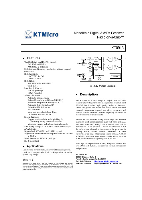
Monolithic Digital AM/FM Receiver Radio-on-a-Chip™KT0913FeaturesWorldwide full band FM/AM support FM: 32MHz-110MHz AM: 500KHz-1710KHz Fully integrated frequency synthesizer with no external components High Sensitivity 1.6uVEMF for FM 16uVEMF for AM High Fidelity SNR (FM/AM): 60dB/55dB THD: 0.3% Low Supply Current 22mA (operating) <15uA (standby) Advanced features Automatic antenna tuning Adjustable AM channel filters (2/4/6KHz) Automatic Frequency Control (AFC) Automatic Gain Control (AGC) Embedded FM SNR meter Fast seek/Tune Integrated stereo headphone driver I2C control interface for MCU Special Features: Support traditional dial and digital key for frequency tuning and volume control Memorize channel and volume in standby mode Low supply voltage: 2.1V to 3.6V, can be supplied by 2 AAA batteries Support both 32.768KHz and 38KHz crystal Support continuous reference frequency from 32.768KHz to 26MHz Small form factor SSOP16L package RoHS CompliantFMINP FMLNA FM Mixer FMAGCADCDACClas sABLOUTVCOLO syntehsizerADCDACClas sABROUTAM LNA AMINP AMINN VCOSysPLLControl Interface Reg bankAMAGC AM MixerXTALKT0913 System DiagramDescriptionThe KT0913 is a fully integrated digital AM/FM radio receiver chip with patented technologies that offer full band AM/FM functionality, high quality audio performance, simple design and low BOM cost thanks to the minimum external components required and direct frequency and volume control interface without requiring customers to modify existing exterior module. Thanks to the patented tuning technology, the receiver maintains good signal reception even with short antennas. The chip consumes merely 22mA current and can be powered by 2 AAA batteries. Another useful feature is that the volume and channel information can be preserved in standby mode without external memories. KT0913 supports a wide range of reference clocks from 32.768KHz to 26MHz, hence can share system clocks with a varieties of MCUs further reducing the system BOM cost. With high audio performance, fully integrated features and low BOM cost, KT0913 is ideal for various applications and products.KT Micro, Inc. 22391 Gilberto, Suite D Rancho Santa Margarita, CA 92688 Tel: 949.713.4000 Fax: 949.713.4004 Copyright ©2010, KT Micro, Inc.ApplicationsDesktop and portable radio, mini/portable audio systems, clock radio, campus radio, PMP docking station, car audio system, toy and gift.Rev. 1.2Information furnished by KT Micro is believed to be accurate and reliable. However, no responsibility is assumed by KT Micro for its use, nor for any infringements of patents or other rights of third parties which may result from its use. No license is granted by implication or otherwise under any patent or patent rights of KT Micro, Inc.Table of Content1. Electrical Specification............................................................................................................................ 4 2. Pin List .................................................................................................................................................... 6 3. Function Description ............................................................................................................................... 7 3.1. Overview ............................................................................................................................................. 7 3.2. FM Receiver........................................................................................................................................ 7 3.3. AM Receiver ....................................................................................................................................... 7 3.4. Operation Bands................................................................................................................................. 7 3.5. Standby ............................................................................................................................................... 7 3.6. Crystal and reference clock............................................................................................................... 8 3.7. Digital Signal Processing ................................................................................................................... 8 3.7.1. FM Stereo Decoder ........................................................................................................................ 8 3.7.2. Mute / Softmute.............................................................................................................................. 8 3.7.3. Stereo / Mono Blending ................................................................................................................. 9 3.7.4. Bass ................................................................................................................................................ 9 3.7.5. Stereo DAC, Audio Filter and Driver............................................................................................. 9 3.7.6. AM Bandwidth............................................................................................................................... 9 3.7.7. TUNE ............................................................................................................................................. 9 3.7.8. SEEK.............................................................................................................................................10 3.8. User-Machine Interface ....................................................................................................................10 3.8.1. Programmable band.......................................................................................................................10 3.8.2. Key Mode......................................................................................................................................10 3.8.3. Dial Mode......................................................................................................................................11 3.9. I2C Control Interface .......................................................................................................................13 3.10. Register Bank ....................................................................................................................................15 3.10.1. CHIP ID (Address 0x01)...............................................................................................................16 3.10.2. SEEK (Address 0x02) ...................................................................................................................16 3.10.3. TUNE (Address 0x03)...................................................................................................................16 3.10.4. VOLUME (Address 0x04) ............................................................................................................16 3.10.5. DSPCFGA (Address 0x05) ...........................................................................................................17 3.10.6. LOCFGA (Address 0x0A) ............................................................................................................18 3.10.7. LOCFGC (Address 0x0C).............................................................................................................18 3.10.8. RXCFG (Address 0x0F)................................................................................................................18 3.10.9. STATUSA (Address 0x12) ...........................................................................................................19 3.10.10. STATUSB (Address 0x13) ...........................................................................................................19 3.10.11. STATUSC (Address 0x14) ...........................................................................................................19 3.10.12. AMSYSCFG (Address 0x16)........................................................................................................20 3.10.13. AMCHAN (Address 0x17) ...........................................................................................................21 3.10.14. AMCALI (Address 0x18) .............................................................................................................21 3.10.15. GPIOCFG (Address 0x1D) ...........................................................................................................21 3.10.16. AMDSP (Address 0x22) ...............................................................................................................21 3.10.17. AMSTATUSA (Address 0x24).....................................................................................................22 3.10.18. AMSTATUSB (Address 0x25) .....................................................................................................22 3.10.19. SOFTMUTE (Address 0x2Eh)......................................................................................................22 3.10.20. USERSTARTCH (Address 0x2F).................................................................................................23 3.10.21. USERGUARD (Address 0x30).....................................................................................................23 3.10.22. USERCHANNUM (Address 0x31) ..............................................................................................23 3.10.23. AMCFG (Address 0x33) ...............................................................................................................24 3.10.24. AMCFG2 (Address 0x34h) ...........................................................................................................24 3.10.25. VOLGUARD (Address 0x3Ah) ....................................................................................................24 3.10.26. AFC (Address 0x3Ch)...................................................................................................................25 4. Typical Application Circuit ....................................................................................................................26 5. Package Outline......................................................................................................................................27 6. Revision History.....................................................................................................................................28Copyright ©2010, KT Micro, Inc.27.Contact Information................................................................................................................................28Copyright ©2010, KT Micro, Inc.31. Electrical SpecificationParameter Power Supply Ambient Temperature Symbol AVDD Ta Table 1: Operation Condition Operating Condition Min Relative to AVss 2.1 -30 Table 2: DC Characteristics Symbol Test/Operating Min Condition IFM IAM IAPD Typ 3.3 25 Max 3.6 70 Units V ℃Parameter Current Consumption Standby Current FM Mode AM ModeTyp 21.3 22 14.5Max -Units mA mA μATable 3: FM Receiver Characteristics (Unless otherwise noted Ta = -30~70℃, AVDD= 2.1V to 3.6V) Parameter Symbol Test/Operating Min Typ Max Condition FM Frequency Range Frx 110 32 Sensitivity1,2,3 Sen (S+N)/N=26dB 1.6 2 Input referred 3rd Order IIP3 85 Intermodulation Production4,5 Adjacent Channel Selectivity 35 51 ±200KHz Alternate Channel Selectivity 50 70 ±400KHz Image Rejection Radio 35 AM suppression 50 RCLK frequency 32.768 32.768 26000 RCLK frequency Range8 -100 100 Audio Output Voltage1,2,3,4 32ohm load 90 100 110 Audio Band Limits1,2,4 30 15k ±3dB 1,4,6 Audio Stereo Separation 35 Audio Mono S/N1,2,3,4 55 60 Audio Stereo S/N1,4,6,7 DBLND=1 64 Audio THD1,2,4,6 0.3 De-emphasis Time Constant DE=0 75 DE=1 50 Audio Common Mode Voltage 0.85 Audio Output Load Resistance RL Single-ended 32 Seek/Tune Time 50 Power-up Time 600 Notes: 1. FMOD=1KHz, 75us de-emphasis 2. MONO=1 3. △F=22.5KHz 4. VEMF=1mV, Frequency=32MHz~110MHz 5. AGCD=1 6. △F=75KHz 7. VOLUME<4:0>=11111 8. The supported RCLK frequency is not continuous. Please refer to application notes.Units MHz uVemf dBuVE MF dB dB dB dB KHz ppm mVRMS Hz dB dB dB % μs μs V Ω ms msCopyright ©2010, KT Micro, Inc.4Table 4: AM Receiver Characteristics (Unless otherwise noted Ta = -30~70℃, AVDD= 2.1V to 3.6V) Parameter Symbol Test/Operating Min Typ Condition AM Frequency Range Frx 500 Sensitivity1,2 Sen (S+N)/N=26dB 15 Audio Output Voltage1,2,3,4 32ohm load 60 Audio Mono S/N1,2,3,4 55 Audio THD1,2,4,6 0.3 Antenna inductance L 280 350 Notes: 1. FMOD=1KHz 2. Modulation index is 30% 3. VEMF=1mV, Frequency=500KHz~1710KHz 4. VOLUME<4:0>=11111Max 1710Units KHz uVemf mVRMS dB % uH0.6 420Copyright ©2010, KT Micro, Inc.52. Pin ListTable 5: Pin listPin Num 1 2 3 4 5 6 7 8 9 10 11 12 13 14 15 16Pin Name CH DVSS ROUT LOUT AVSS AVDD XI/RCLK XO ENABLE AMINN AMINP RFINP RFGND SCL SDA VOLDescription Channel adjustment. Digital ground. Right channel audio output. Left channel audio output. Analog ground. Power supply. Crystal input/Reference clock input. Crystal output. Chip enable. Tied to an internal 600kohm pull down resistor. AM RF negative input. AM RF positive input. FM RF input. RF ground. SCL of I2C interface. Tied to an internal 47kohm pull-up resistor. SDA of I2C interface. Tied to an internal 47kohm pull-up resistor. Volume adjustment.Figure 1: KT0913 Pin assignment (Top view)Copyright ©2010, KT Micro, Inc.63. Function Description3.1. OverviewKT0913 offers a true single-chip, full-band FM/AM and versatile radio solution by minimizing the external components and offering a variety of configurations.3.2. FM ReceiverKT0913 enters FM mode by setting register AM_FM to 0. The FM receiver is based on the architecture of KT Micro’s latest generation FM receiver chips in mass production. There are no external filters or frequency-tuning devices thanks to a proprietary digital low-IF architecture consisting of a fully-integrated LNA, an automatic gain control (AGC), a set of high-performance ADCs, high-quality analog and digital filters, and an on-chip low-noise self-tuning VCO. The on-chip high-fidelity Class-AB driver further eliminates the need for external audio amplifiers and can drive stereo headphones directly.3.3. AM ReceiverKT0913 enters AM mode by setting register AM_FM to 1. The AM Receiver employs a similar digital low IF architecture and share many circuits with the FM receiver. The AM receiver supports a wide band from 500KHz to 1710KHz also known as the popular AM bands. The AM channel spacing can be set to 1KHz, 9KHz or 10KHz to address different applications. The bandwidth of the channel filter can be set to 2KHz, 4KHz or 6KHz to suit various requirements. The AM receiver in KT0913 can provide accurate and automatic AM tuning without manual alignment. It supports 350uH ferrite loop antenna with +/- 25% tolerance.3.4. Operation BandsKT0913 supports wide FM band and AM bands. The FM receiver covers frequencies from 32MHz to 110MHz. The 32MHz to 64MHz is defined as Campus Band in KT0913 and can be enabled by setting CAMPUSBAND_EN register to 1. The AM band is from 500KHz to 1710KHz.3.5. StandbyKT0913 supports both Software Standby mode and Hardware Standby mode. To enter Software Standby, the STANDBT register shall be set to 1 through I2C interface. To enter Hardware Standby, the ENABLE pin is pulled down to ground. In the standby modes, the internal state (channel, volume) is preserved and can be recovered when the chip wakes up from the standby.Copyright ©2010, KT Micro, Inc.73.6. Crystal and reference clockKT0913 integrates a low frequency crystal oscillator that supports 32.768KHz and 38KHz crystals. Alternatively a CMOS level external reference clock may be used by setting the RCLK_EN register to 1 and setting REFCLK<3:0> according to the frequency of the reference clock.3.7. Digital Signal Processing3.7.1. FM Stereo DecoderThe digitized IF signal is fed to the FM demodulator which demodulates the signal and outputs a digital multiplexed (MPX) signal consisting of L+R audio, L-R audio, 19KHz pilot tone and RDS signal. The left channel signal and the right channel signal can be extracted from the MPX signal by simply adding and subtracting the L+R signal and L-R signal. The spectrum diagram is shown in Figure 2.Figure 2: Spectrum diagram of the MPX signal3.7.2. Mute / SoftmuteKT0913 can be hard muted by setting DMUTE to 0 and the output of the audio signal is set to the common mode voltage. There is also a Soft Mute feature that is enabled by setting FMDSMUTE to 0 in FM mode and AMDSMUTE to 0 in AM mode. In this mode, the audio volume is gradually attenuated when the signal reception is bad (i.e. when the RSSI is below a certain level as defined by FM_SMTH<2:0> and AM_SMTH<2:0>, respectively.) The attenuation attack rate and depth can be configured through SMUTER<1:0> and SMUTEA<1:0>, Copyright ©2010, KT Micro, Inc. 8respectively. The target volume can be configured through VOLUMET<4:0>. SNR value can also be used as the judgment threshold in FM mode by setting SMMD to 1.3.7.3. Stereo / Mono BlendingIn order to provide a comfortable listening experience, KT0913 blends the stereo signal with mono signal gradually when in weak reception in FM mode. The signal level range over which the blending occurs is set by BLNDADJ<1:0>. The blending is disabled when DBLND is set to 1. MONO playback mode can be forced by setting the MONO to 1. If the MONO bit and the INV_LEFT_AUDIO bit are both set to 1, then a fully differential signal will be output at the LOUT and ROUT.3.7.4. BassKT0913 provides bass boost feature for audio enhancement. The gain of the bass boost can be programmed through BASS<1:0>. With BASS<1:0>=00, this feature is disabled.3.7.5. Stereo DAC, Audio Filter and DriverTwo high-quality single-bit ΔΣ audio digital-to-analog converters (DAC) are integrated along with high-fidelity analog audio filters and class AB drivers. Headphones with impedance as low as 16ohms can be directly driven without adding external audio drivers. An integrated anti-pop circuit suppresses the click-and-pop sound during power up and power down. For different load capacitor, user can set different anti-pop configuration through POP<1:0>.3.7.6. AM BandwidthKT0913 provide programmable AM channel bandwidth through AM_BW<1:0>.3.7.7. TUNEThe fully integrated LO synthesizer supports wide band operation. Channel tuning is started when the register AMTUNE/FMTUNE is set to 1. In FM mode, the channel frequency is set by FMCHAN<11:0> and is defined as Freq(MHz) = 50KHz × FMCHAN<11:0> In AM mode, the channel frequency is set by AMCHAN<10:0> and is defined as Freq(KHz) = 1KHz × AMCHAN<10:0>Copyright ©2010, KT Micro, Inc.93.7.8. SEEKKT0913 offers an effective software based seek algorithm. Refer to application notes for more information.3.8. User-Machine InterfaceChannel and volume can be adjusted not only by setting corresponding FMCHAN, AMCHAN and VOLUME registers, but also by using built-in user-machine interface. Two types of user-machine interface, Key Mode and Dial Mode, are provided by KT0913. In these modes, the channel and volume are controlled by KT0913 itself.3.8.1. Programmable bandKT0913 supports programmable arbitrary frequency range of the operation band by setting register USERBAND to 1. Information of the current band, such as AM/FM mode, upper and lower edge of the band, channel step and the number of guard channel used in Dial Mode, should be written to KT0913 once the band is chosen, which is sensed by MCU. The number of channels and start channel are defined in register USER_CHAN_NUM<11:0> and USER_START_CHAN<14:0>. In FM mode, where register AM_FM is set to 0, the lower and upper bound of the current band can be express as: f bot = USER _ START _ CHAN < 14 : 0 > ×50 KHzf top = f bot + USER _ CHAN _ NUM < 11 : 0 > × f step Where f step is the channel step, which can be configured by register FMSPACE<1:0>. In AM mode, where register AM_FM is set to 1, the corresponding lower and upper bound of the band are: f bot = USER _ START _ CHAN < 14 : 0 > ×1KHzf top = f bot + USER _ CHAN _ NUM < 11 : 0 > × f stepWhere f step is the channel step, which can be configured by register AMSPACE<1:0>.3.8.2. Key ModeKT0913 allows user to control the channel and volume by using keys/buttons to send digital control signals to CH and VOL pins. Please refer to Section 4 for a typical application circuit. The key mode is enabled by setting GPIO1<1:0> and GPIO2<1:0> to 01.Copyright ©2010, KT Micro, Inc.10Each time VOLP/VOLM key is pressed, the volume increases/decreases by 2dB. If the VOLP/VOLM key is pressed and held, the volume will continue to increase/decrease at 2dB steps until the key is released. When configured in Key Mode, KT0913’s channel selection has two working modes. Mode A: If KEY_MODE<1:0> is set to 00, Mode A is selected. In this mode, each time the CHP (CHM) is pressed, the channel frequency increases (decreases) by one step. The step sizes are defined by FMSPACE<1:0> and AMSPACE<1:0>. If the CHP (CHM) key is pressed for and held for a certain time (defined by TIME1<1:0>), the channel frequency will continue to increase (decrease) automatically at a certain pace (as defined by TIME2<2:0>) until the key is released. Mode B: If KEY_MODE<1:0> is set to 01, Mode B is selected. In this mode, each time the CHP (CHM) is pressed, the channel increases (decreases) by one step. The step sizes are defined by FMSPACE<1:0> and AMSPACE<1:0>. If the CHP (CHM) key is pressed and held for a specific time (TIME1<1:0>), the channel will continue to increase (decrease) automatically at a certain pace (TIME2<2:0>) even if the key is released. The movement is stopped when the key is pressed again.3.8.3. Dial ModeKT0913 supports a unique Dial Mode whose application circuit is shown in Figure 3. The dial is implemented by a variable resistor with the center tap connected to the chip. KT0913 measures the divider ratio of two parts of the variable resistor and maps the result to the real control parameters, such as channel frequency, volume, etc. The channel controller enters dial mode by setting register GPIO1<1:0> to 10. The illustration circuit is shown in Figure 3 错误!未找到引用源。
vue动态拼接方法

vue动态拼接方法Vue是一种流行的JavaScript框架,用于构建用户界面。
在Vue中,我们可以使用动态拼接方法来动态生成代码。
这种方法非常灵活,可以根据不同的条件和数据生成不同的代码块,从而实现更加智能和可复用的组件。
本文将介绍Vue动态拼接方法的使用和应用场景。
让我们来了解一下Vue中动态拼接方法的基本语法。
在Vue中,我们可以使用双花括号{{}}来插入动态的JavaScript表达式。
这些表达式可以包含变量、运算符、函数调用等,从而实现动态生成代码的功能。
例如,我们可以使用v-if指令来根据条件动态渲染元素:```<template><div><p v-if="isShow">{{ message }}</p></div></template><script>export default {data() {return {isShow: true,message: 'Hello, Vue!'}}}</script>```在上面的例子中,我们使用了isShow变量来控制是否显示message变量的内容。
当isShow为true时,元素<p>{{ message }}</p>会被渲染出来,否则不会显示。
除了在模板中使用动态拼接方法,我们还可以在JavaScript代码中动态生成代码块。
Vue提供了一些方法来实现这个功能。
例如,我们可以使用Vue.extend方法来动态创建Vue组件:```<template><div><component :is="dynamicComponent"></component> </div></template><script>export default {data() {return {dynamicComponent: ''}},created() {this.dynamicComponent = Vue.extend({template: '<p>{{ message }}</p>',data() {return {message: 'Hello, Vue!'}}})}}</script>```在上面的例子中,我们使用Vue.extend方法动态创建了一个Vue 组件,并将其赋值给dynamicComponent变量。
vue 动态组建组建获取实例

vue 动态组建组建获取实例在Vue 中,动态组件允许你在一个页面中根据需要切换多个组件。
动态组件由 component 标签定义,并且可以动态地绑定到不同的组件实例。
要获取动态组件的实例,你可以使用 this.$refs 对象。
$refs 是一个对象,其中包含了当前Vue 实例中所有的引用(ref)。
你可以通过在组件标签上添加 ref 属性来为组件指定一个唯一的标识符,然后使用 $refs 对象来访问该组件的实例。
下面是一个示例代码,展示了如何动态获取动态组件的实例:html复制代码:<template><div><button @click="switchComponent">切换组件</button><component :is="currentComponent" ref="dynamicComponent"></component></div></template><script>import ComponentA from './ComponentA.vue';import ComponentB from './ComponentB.vue';export default {data() {return {currentComponent: 'ComponentA',};},methods: {switchComponent() {this.currentComponent = this.currentComponent === 'ComponentA' ? 'ComponentB' : 'ComponentA';},getDynamicComponentInstance() {const componentInstance = this.$refs.dynamicComponent;// 在这里可以访问动态组件的属性和方法console.log(componentInstance.someMethod());},},};</script>在上面的示例中,我们定义了两个组件 ComponentA 和 ComponentB,并通过 currentComponent 数据属性来动态切换显示的组件。
在template中使用vnode

在template中使用vnode在Vue.js中,template是用来描述UI组件的结构和样式的。
而vnode(虚拟节点)则是Vue.js内部用来描述组件的数据和行为的对象。
在使用Vue.js开发应用的过程中,我们常常需要使用vnode 来实现一些特殊的功能,比如动态组件、异步组件、render函数等等。
在template中使用vnode,一般有两种方式:1.使用组件的render函数Vue.js中每个组件都有一个render函数,用来生成vnode。
我们可以在template中使用组件的render函数来生成vnode,并将其渲染到页面上。
例如:```<template><div><my-component :message='message' /></div></template><script>import MyComponent from './MyComponent.vue';export default {components: {MyComponent,},data() {return {message: 'Hello World',};},render(createElement) {return createElement(MyComponent, {props: {message: this.message,},});},};</script>```在上面的例子中,我们在template中使用了组件MyComponent 的render函数来生成vnode,并将其渲染到页面上。
这个render函数接收一个名为createElement的函数作为参数,我们可以通过它来创建vnode。
在这个函数中,我们将MyComponent作为第一个参数传递给createElement函数,并将props.message作为第二个参数传递给它。
vue3 import方式动态使用组件传参数

vue3 import方式动态使用组件传参数在Vue 3中,可以使用动态导入和动态注册的方式来动态使用组件并传递参数。
以下是一个示例:首先,确保你已经安装了Vue 3和Vue Router。
在你的代码中,可以使用`import()`函数来动态导入组件。
例如,假设你有一个名为`DynamicComponent`的组件,可以通过以下方式动态导入它:```javascriptconst DynamicComponent = () => import('./DynamicComponent.vue');```接下来,你可以在需要使用这个动态组件的地方,使用`component`选项来注册这个动态组件。
例如,你可以在Vue Router的路由配置中动态加载组件如下:```javascriptconst routes = [// 其他路由配置...{path: '/dynamic',name: 'DynamicComponent',component: () => import('./DynamicComponent.vue')}]```这样,当用户访问`/dynamic`路径时,Vue Router会动态加载并渲染`DynamicComponent`组件。
如果你需要传递参数给动态组件,可以使用`props`选项来传递。
例如,你可以通过路由参数传递参数给动态组件:```javascriptconst routes = [// 其他路由配置...{path: '/dynamic/:id',name: 'DynamicComponent',component: () => import('./DynamicComponent.vue'),props: true}]```然后,在`DynamicComponent`组件中,可以通过`props`来接收该参数:```javascriptexport default {props: ['id'],// 其他组件选项...}```这样,当用户访问`/dynamic/123`时,`123`就会作为`id`属性传递给`DynamicComponent`组件。
configurationmanager.connectionstrings 用法 -回复

configurationmanager.connectionstrings 用法-回复configurationmanager.connectionstrings是一个用于访问和管理应用程序配置文件中连接字符串的类。
在.NET开发中,连接字符串是一种用于连接到数据库、文件等存储资源的重要参数。
配置文件是一个XML 文件,通常用于存储应用程序的设置和配置信息。
本文将详细介绍configurationmanager.connectionstrings类的用法,并提供一些具体的示例来帮助读者更好地理解。
首先,我们需要引入System.Configuration命名空间,这个命名空间包含了configurationmanager.connectionstrings类。
在代码中,我们可以通过using关键字来简化命名空间的使用,即using System.Configuration。
接下来,我们需要在配置文件中定义连接字符串。
通常,配置文件的名称为App.config(Windows应用程序)或Web.config(Web应用程序),位于应用程序的根目录下。
我们可以使用任何文本编辑器来编辑配置文件。
在配置文件中,我们可以使用connectionStrings元素来定义连接字符串。
例如,以下是一个简单的连接字符串定义:<connectionStrings><add name="MyConnection"connectionString="Server=localhost;Database=MyDatabase;User Id=sa;Password=123456;" providerName="System.Data.SqlClient"/></connectionStrings>在上面的示例中,我们定义了一个名为“MyConnection”的连接字符串,它连接到本地的数据库“MyDatabase”,使用了SQL Server的提供程序“System.Data.SqlClient”。
常用的一些测试英语缩写
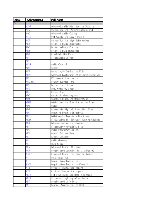
Full Name
Advanced Audio Distribution Profile Authentication, Authorization, and Accounting Advanced Audio Coding ATM Adaptation Layer type 1 Authentication Algorithm Number Activity-Based Buggeting Activity-Based Costing Activity-Base Management Available Bit Rate Alternating Current Audio Coder-3 Accept Anisotropic Conductive Film Advanced Configuration & Power Interface AT Command Interpreter Acknowledgement SMS Access Control List Add, Compare, Select Agency Dept. Automatic data capture Absolute Dimension Measurement Administration Function at the LIAN Audio Asymmetric Digital Subscriber Line Adaptive Dynamic Threshold Additional Elementary Functions Association for Electric Home Appliances Advance Encryption standard Alternative Frequency List Audio Frequency Control Annual Failure Rate Access Gateway Audio Gateway Anti-Glare Advanced Global Alignment Accelerated Graphics Port、Advanced Graphics Port Assisted Global Positioning System Auto Insertion Acquisition Indicatior Acquisition Indication Channel Article Inspection report Article Inspection report ATM Line Interface Module subrack alternate lighting of surfaces Accelerated Life Test General Administration Dept.
关于远动的英语作文

关于远动的英语作文English Response:Dynamic Stretching: An Essential Component of Exercise.Dynamic stretching plays a crucial role in my fitness routine, aiding in enhancing flexibility, preventing injuries, and improving overall performance. It's apractice I've incorporated into my workouts for years, and its benefits are undeniable.One of the key advantages of dynamic stretching is its ability to activate muscles and prepare them for the demands of exercise. Unlike static stretching, where you hold a position for an extended period, dynamic stretching involves continuous movement through a full range of motion. For example, before a run, I perform leg swings, lungeswith a twist, and arm circles to loosen up my muscles and joints. This not only primes my body for the upcomingactivity but also helps improve my range of motion.Moreover, dynamic stretching can help prevent injuries by promoting blood flow and increasing body temperature. By gradually increasing blood flow to the muscles and joints, dynamic stretching reduces the risk of strains and sprains during exercise. I've experienced firsthand how dynamic stretching before weightlifting sessions has helped me avoid muscle pulls and strains, allowing me to lift heavier weights safely.Another benefit of dynamic stretching is its positive impact on athletic performance. By actively engaging muscles and mimicking movements specific to the activity, dynamic stretching helps improve coordination, balance, and agility. For instance, before playing basketball, I incorporate dynamic stretches like high knees, butt kicks, and lateral lunges to prepare my body for the dynamic movements required on the court. This not only enhances my performance but also reduces the likelihood of fatigue and muscle stiffness during the game.In addition to its physical benefits, dynamicstretching also serves as a mental warm-up, helping me focus and prepare mentally for the workout ahead. The rhythmic movements and focus required during dynamic stretching create a sense of mindfulness and concentration, setting the tone for a productive exercise session.Overall, dynamic stretching is an essential component of any exercise routine, offering a myriad of benefits for both the body and mind. By incorporating dynamic stretches into my workouts, I've not only improved my flexibility and performance but also reduced the risk of injuries, allowing me to enjoy a more fulfilling and sustainable fitness journey.中文回答:动态拉伸,锻炼不可或缺的一环。
- 1、下载文档前请自行甄别文档内容的完整性,平台不提供额外的编辑、内容补充、找答案等附加服务。
- 2、"仅部分预览"的文档,不可在线预览部分如存在完整性等问题,可反馈申请退款(可完整预览的文档不适用该条件!)。
- 3、如文档侵犯您的权益,请联系客服反馈,我们会尽快为您处理(人工客服工作时间:9:00-18:30)。
Vol.3,No.2Special issue:.NET:The Programmer’s Perspective:ECOOP Workshop2003 Dynamic Component Composition Anis Charfi,David Emsellem,Michel Riveill,Laboratoire I3S,Bˆa timent ESSI,BP145,06903Sophia Antipolis CEDEX,FranceComponents have brought with them the notion of services which let the programmer concentrate on the business behavior of his component while the non functional part(i.e.the services)is the responsibility of the platform provider.Thus services are notreusable throughout the different platforms;the mechanism used to integrate them in the component is totally platform dependant.In this paper we propose a model to define the integration of services and describe its implementation in framework.We also discuss the facilities offered by platform in comparison with thefirst implementation of this model which was in Java.1INTRODUCTIONNowadays,adding and composing non-functional requirements at deployment time or at runtime have become a ubiquitous way to deal with service integration such as transaction,security,replication and other high-level features.Deployment in component models.To partially achieve the static service inte-gration,component models such as CORBA Component Model(CCM)and Enter-prise Java Beans(EJB)have emerged.Those standards specify how some services can be statically plugged into components.One of the most important contribu-tions in component models is to separate application programming from deployment. Indeed,deployment descriptors allow component programmers to give information about which services to use.Then the deployer has to customize the deployment descriptor in order to adapt the component to the specificity of the runtime envi-ronment(transaction,persistency,security,database support,etc.).According to a deployment descriptor,generators provided by platforms generate adequate interpo-sition code.So,the integration of services by the deployer is basically done through a parameterfile.As the definition of the services is integrated into the platform, their evolution and composition is handled by the platform.Consequently,we could suppose that the deployer does not have to deal neither with the application code nor with the generated code.Deployment drawbacks in component models.However,the code generators support only services provided by the platform.For using new services like replicated EJB for example,the deployer must either modify the generated code or specialize the generator if it is open-source[6],[5].So,it is a difficult task,because service Cite this article as follows:Anis Charfi,David Emsellem,Michel Riveill:Dynamic Com-ponent Composition ,in Journal of Object Technology,vol.3,no.2,Spe-cial issue:.NET:The Programmer’s Perspective:ECOOP Workshop2003,pages37–46, http://www.jot.fm/issues/issue200402/article4DYNAMIC COMPONENT COMPOSITION calls must be plugged either in the generated code or in the code to generate.This makes maintenance,evolution and service composition quite impossible to manage. Moreover,as the code integration is predefined,the deployer has no high level way to adapt the code generation nor to control the composition of existing services. This is needed for example in order to modify or to trace access to persistent data. Finally,these component models do not allow neither dynamic service integration nor dynamic customizations of a single component instance.Reflection and dynamic service integration.Run-time reflection is a powerful technique that is successfully used to implement non-functional requirements such as load balancing,fault tolerance and security[2],[9],[10],[11].The code that realizes the non-functional requirements is expressed as meta-programs using a meta-object protocol to reflect the base-level behavior.Generally,these works apply to expert programmers able to deal with reflection.So they are often used by the platform providers,who hide these techniques inside the provided libraries.But we have shown that the deployer still needs to partially do the same job to integrate new services for example.However he/she is not necessarily an expert in reflective systems.Aspect oriented approach[?],[8],[11]proposes to define code integration as”aspects”,providing a way to meta-program in a declarative form2OUR APPROACH:DYNAMIC CONFIGURATION BASED ON IN-TERACTION PATTERNS.We propose to define dynamic services integration using a rule language.We have chosen to present it throughout examples.Our goal is to intercept invocations at least with similar controls as the ones generated by the Jonas EJB platform,in order to bear out our approach.So,we have defined integration of several services [6].At the class level,interaction patterns describe all the possible connections among classes of the application.At the instance level,reified interactions represent actual connections among instances.An interaction pattern is expressed by rules (written in a specific language,based on Interaction Specification Language ISL[4]). An ISL interaction rule describes how the behaviour of an object should change when it interacts with another one.It consists of two parts:the left side is the notifying message and the right side is the reaction to that message.In object-oriented languages,behaviours correspond to class methods.To show how interactions are created and used,we will take as an example the connection between a component and a security manager.Several mechanisms could be used to reach secure execution of an application.As afirst step,we have chosen,to check the validity of invocation by a call to a security manager,which raises an exception if the invocation is not allowed.Figure1shows the interaction pattern describing such integration.The interaction modifies the behaviour of the JBean component.When this component is accessed by a controlled method and 38JOURNAL OF OBJECT TECHNOLOGY VOL3,NO.22OUR APPROACH:DYNAMIC CONFIGURATION BASED ON INTERACTION PATTERNS.interaction SecurityPattern(JBean B,SecurityManager S){B.*->if(S.checkSecurity(_call))B._callelseexception("unauthorized user")}Figure1:Interaction pattern for dynamic integration of the security service the security manager forbids the execution an exception is raised,otherwise the callis executed.The interaction pattern security,when plugged on components,will control any call that can be”unified”with one of the operations to control.The”.”operator in left part of the interaction rule denotes the message reception.The operator* stands for any message(method calls)and the operator->expresses that the code in right part of the interaction rule is executed as a reaction to the notifying message (i.e.the call to the business method).The method call is reified as an object,which is designed by the operator call.During execution,an end-user may decide to use this interaction pattern to connect an account instance of JBean(say,MyAccount)to an instance of Security-Manager(say LocalManager)and dynamically integrate the security service on the component MyAccount.Interaction patterns represent models for component interactions.They contain one or more interaction rules expressing the control that should be executed on the connected components.An interaction rule consists of two parts:the left side is the notifying message and the right side is the reaction.Both sides are separated by the ->operator.Interaction patterns are specified in the Interaction Specification lan-guage ISL.The ISL language allowsthe specification of interactions independently of the application language.It defines many operators such as the conditional opera-tor(if...then...else...endif),the sequence operator(;),the concurrency operator (//),waiting operators,exception handling and others.Implementation of the interaction model.We have adapted our prototype build for Java component model[1],[3],[4]to the component model offer by the CLI to allow dynamic service integration using interaction rules for all languages supported by the CLI platform.We also attempted to define interactions across different platforms,so that we can connect component to a Java component by means of interaction patterns.VOL3,NO.2JOURNAL OF OBJECT TECHNOLOGY39DYNAMIC COMPONENT COMPOSITION 3PORTING AN INTERACTION SERVICE FROM JAVA Structure of the interaction serviceThe interaction service can be split into two main parts.The Interaction Server on the one hand and the component management services on the other hand.The Interaction Server acts as a central repository for interaction patterns and provides methods for pattern instantiation as well as for rule merging.Rule merging is required when two interaction rules with the same notifying message are applied to a component.The component management services include the execution of in-teraction rules,the management of interactions(adding,removing,call redirection), inter-component communication(using proxies)and code instrumentation tools such as GenInt.Our purpose was to extend the interaction model and components without rewriting the interaction server.Therefore we only ported the component management services to platform and we reused the Java interaction sever (called Noah).Independently of the targeted platform interaction rules should be represented as an abstract tree.The tree comprises several node types respectively to the actions that can be specified in ISL(Concurrency,Sequence,if then else etc).Another constraint is communication components and the java interaction server.It is required during two phases of the interaction lifecycle.Thefirst time is when an interaction pattern is instantiated.The server needs somehow to talk to the target components and hand them the respective interaction rules.Those rules are available at the server as tree of java objects.They need to be packed appropriately before accessing world.We have chosen to serialize them in XML.This is a universal format which can be easily handled in both Java .The second time communication is needed is when more than one interaction rule is applied to the same notifying message of a component.In this case the rules should be merged so that we have only one reaction for each notifying message.As we said before rule merging belongs to the tasks of the interaction server.Since it is already implemented in Java we wanted to reuse it.Therefore we exposed the merging service components using a webservice.Component code instrumentationAn interacting component modifies its behaviour dynamically according to the cur-rent interaction rules.This ability has to be acquired by the component and there-fore it must be prepared to manage interactions and execute them.The interaction server needs among other things to instantiate and remove interaction rules from the 40JOURNAL OF OBJECT TECHNOLOGY VOL3,NO.24IMPLEMENTING THE INTERACTION SERVICE component.Moreover the component should store the interaction rules that affect it.This transformation makes a component”Noah compliant”.The component class is modified in such a way that it provides an interaction management interface (addRule,removeRule,getBehaviour)as well as wrappers for the business methods (call interception)and additionalfields to store the interaction rules.In Java this task is accomplished by the GenInt tool.It instruments the class bytecode using the BCEL library.We developed a similar tool components which assemblies.4IMPLEMENTING THE INTERACTION SERVICE In this part will we discuss some technical details concerning the implementation of the component management services compared with Java.In addition we show to which extent platform helped us.We also address some aspects where we think platform should provide more support to the programmer. ThreadingAn ISL tree represents the reaction to a notifying message.Each component should be able to execute reactions.A reaction is an abstract ISL tree with several types of nodes e.g.notify call,global call,assignment,sequence etc.The execution of the tree is multithreading and requires therefore thread synchronisation.When the executor thread comes to a concurrency node(reaction with several parallel sub-reactions)it starts a new child thread for each sub-reaction.The par-ent thread blocks and waits until all child threads framework provides the Join()method in the class System.Threading.Thread which makes the current thread wait till another thread exits.Java does not provide the Join func-tionality.For this reason we used the methods wait()and notify()of the class ng.Object to get this functionality.We derived a class ReactionThread from ng.Thread.A ReactionThread has a reference to its parent thread.This ref-erence is needed to wake up the waiting father thread(call notify())at the end of the run()method.ISL trees also include qualified message nodes and waiting message nodes.A qualified message is a labelled message e.g.[1]obj1.method1().The label enables other nodes to reference the qualified message node and in particular allows waiting message nodes to block till the execution of the qualified message exits.When the executor comes to a waiting message node e.g.obj2.method2()@X itfirst checks if the message with label[X]has been executed.If not the executor waits till it gets notified of the end of the execution of the message labelled by X. we used the ManualResetEvent class for inter-thread communication. This class notifies one or more waiting threads that an event has occurred.We VOL3,NO.2JOURNAL OF OBJECT TECHNOLOGY41DYNAMIC COMPONENT COMPOSITION associate a ManualResetEvent instance with each qualifier(label)in the ISL tree. When the executor visits a waiting message it retrieves the corresponding Manual-ResetEvent instance and calls the WaitOne()method on it.This results in blocking the executor thread so long as the respective qualified message has not been exe-cuted.When the executor visits a qualified message it calls the Set()method which sets the state of the ManualResetEvent object to signalled and releases all waiting threads.Hence the execution of the waiting message resumes.Java does not provide a similar concept to synchronisation events.For this reason we created our own.The class MessageMutex is used for thread synchronisation in Java;it holds a vector of waiting threads.A MessageMutex object is initially locked. The unlock()method releases the MessageMutex and notifies all waiting threads.In conclusion the System.Threading namespace provides many useful classes that considerably reduce the work for the programmer.However these con-cepts(monitor,lock,synchronisation events,join,...)can be also implemented in Java with some additional coding.ReflectionWe used code instrumentation in order to make a class”Noah compliant”.We developed therefore the previously mentioned tool GenInt.It is available for both Java .In Java GenInt works at the bytecode level whereas it operates on the MSIL level .GenInt inserts newfields,methods and constructors to a class and modifies some of its methods and Constructors.The basis for GenInt is the Reflection mechanism.Compared to Java framework provides a more powerful reflection API. It is sort of a”read-write”API while a”read-only”API in Java.The Sys-tem.Reflection.Emit namespace in framework contains several classes that allow programmers to dynamically create new types at runtime.The TypeBuilder class defines and creates new instances of classes during execution while the classes FieldBuilder and MethodBuilder create new class members.We can even dynami-cally create code at runtime using the class ILGenerator.In Java reflection only allows programs to interrogate objects at runtime about their members,their access modifiers and their parent class.Dynamic method invocation is also provided but all the classes and the methods must be defined at compile-time.This means we can neither dynamically create a new class nor even add afield into a given class.Nevertheless,The emitting functionality is not really part of the reflection in the OOP sense but it is rather a bonus .On the other hand,we missed some important methods in reflection API such as a GetMethodBody method in the class MethodInfo that returns an array of IL instructions representing the body of a method.We also expected to retrieve somehow information about reflection we can not find out which exceptions a given method catches or may throw.42JOURNAL OF OBJECT TECHNOLOGY VOL3,NO.24IMPLEMENTING THE INTERACTION SERVICE //a method wrapper public double foo(int num,Object obj){...if(rule){//int num is automatically converted to an objectreturn reactionExecutor.execute(‘‘foo’’,new object[]{num,obj});}else{foo_INITIAL(num,obj);}}Figure2:Type unification Another problem is related Emitting.In fact,when emitting new types is not possible to create a new Type starting from another type.Let us examine this through an example:we have defined a class Foo and we want to dynamically create a new class FooName which is the same as Foo except that it has a string field name more.We want to tell the TypeBuilder object”do not start from scratch but start from Foo”.Unfortunately this is not possible.Instead we have to traverse all members of Type Foo using reflection(fields,methods,events,properties,con-structors and their access modifiers),then we create a TypeBuilder for FooName and consequently add all members of Foo into the TypeBuilder object.Thereby it is easy to copy thefield members and method headers but not the bodies of con-structors or methods.To achieve this we used a PEfile Reader library.We hope that in the next release,PE Reader/Writer classes will be integrated to framework.Type UnificationThe code instrumentation tool GenInt creates wrappers for the component’s business methods.A wrapper intercepts the method call and checks whether any interaction is applied to that method.If yes the reaction to the rule should be executed.That means the method parameters should be passed to the reaction executor(as an array of objects) every thing is an object.The type system unification provides value types with the benefits of object-ness and thus bridge the gap that exists in many other languages such as Java.This means ValueTypes as well as Reference-Types are derived from the ultimate base class System.object.In situations where value types need to be treated as objects,the CLR automatically converts them to objects.This process is called boxing.The reverse process is called unboxing.Both transformations are totally transparent to the programmer.Java has another approach on data types.It differentiates between primitive types and classes.Primitive types are not inherited from the ng.Object class and must therefore be treated specially.Unlike C#,wrapping and unwrapping in VOL3,NO.2JOURNAL OF OBJECT TECHNOLOGY43DYNAMIC COMPONENT COMPOSITION public double foo(int num,Object obj){...if(rule){//does the method return a double or a DoubleClass returnClass=double.class;//wrap int num to an IntegerInteger numInt=new Integer(num);//method based on reflectionObject objet=reactionExecutor.execute("foo",new Object{numInt,obj});//get the class of the return object:Double...//what shall we return a Double or a double?Double retDouble=(Double)objet;//returnClass is double.class so unwrap and return a doublereturn retDouble.doubleValue();}else{foo_INITIAL(num,obj);}}Figure3:Wrapping and Unwrapping in Javajava must be managed by the programmer using wrapper classes such as Integer, Double,Boolean etc.Further more if a method(such as the reflection-based in-vocation method:Object invoke(String methodName,Object[]parameters)returnsan Object of class Double for instance,we should be smart enough to know if this Double is a real Double or a primitive double.We have therefore some overhead because we must store somewhere the real return type that we expect.Language InteroperabilityThe common language runtime CLR provides the necessary foundation for language interoperability by specifying and enforcing a common type system and by providing metadata[7].Language interoperability is a great advantage we had while portingthe interaction platform from Java .We did the code instrumentation atthe MSIL level and thus we could seamlessly support many languages such as Vi-sualBasic,C#,Eiffel,Cobol and others.This is due to the fact that all languages targeting the CLR follow the common type system rules for declaring and using types.The common type system plays a similar role to the IDL in Corba or type44JOURNAL OF OBJECT TECHNOLOGY VOL3,NO.25CONCLUSIONlibraries in COM.In fact it is also possible to compile many programming languages to Java bytecode but they can not really share and extend each others libraries simply because Java has no match to the Common Type System.5CONCLUSIONThis paper describes our experience with platform.We partially ported an Interaction Service(originally implemented in Java)and now are able to provide that service components too.This experience was very valuable for us at least in two respects.First we gained insight into many interesting aspects provided by environment such as remoting,threading,reflection and Web Services.The rich set of capabilities framework made our task easier to achieve.In particular the reliable language interoperability enabled us to target many languages such ,C#and Cobol.Secondly,by porting the service into a new platform,we worked out a set of core functionalities that must be ported in order to support other component platforms. Thus we have a kind of cookbook that can be used to extend the interaction model to Corba Component Model for example.REFERENCES[1]L.Berger.Mise enœuvre des interactions en environnements distribu´e s,com-pil´e s et fortement typ´e s:le mod`e le”MICADO”.PhD thesis,Universit´e de Nice-Sophia Antipolis,2001.[2]E.Bergmans and M.Aksit.Constructing reusable components with multipleconcerns using compositionfilters.In M.Aksit,editor,Software Architectures and Component Technology:The State of the Art in Research and Practice.Kluwer Academic Publishers,2000.[3]L.Bussard.Towards a pragmatic composition model of corba services basedon aspectj.In ECOOP’s Workshop on Aspect and Dimensions of Concerns, Cannes,France,2000.[4]M.Fornarino,A.-M.Pinna,and S.Moisan.Distributed access knowledge-based systems:Reified interaction service for trace and control.In International Symposium on Distributed Object Applications(DOA2001),Roma,Italy,2001.[5]JBoss./.[6]JOnAS.Javatm open application server./jonas/jonasHomePage.htm.VOL3,NO.2JOURNAL OF OBJECT TECHNOLOGY45DYNAMIC COMPONENT COMPOSITION [7]MSDN library..[8]H.Ossher,W.Harrison, F.Budinsky,and I.Simmonds.Subject-oriented programming:Supporting decentralized development of objects./sop/.[9]R Pawlak,L.Duchien,and G.Florin.An automatic aspect weaver with areflective programming language.In Workshop on Meta-Level Architectures and Reflection,Reflection’99.Springer Verlag,LNCS1616,1999.[10]B.Robben,B.Vanhaute,W.Joosen,and P.Verbaeten.Non-functional poli-cies.In Workshop on Meta-Level Architectures and Reflection,Reflection’99.Springer Verlag,LNCS1616,1999.[11]P.Tarr,M.D’Hondt,L.Bergmans,and C.V.Lopes,editors.ECOOP’s Work-shop on Aspects and Dimensions of Concern:Requirements on,Challenge Prob-lems For,Advanced Separation of Concerns,Cannes,France,2000.ABOUT THE AUTHORSAnis CharfiAnis Charfiis a PhD student at the Darmstadt Uni-versity of Technology.During his master thesis within the Rainbowteam he implemented the interaction model .He can bereached at charfi@informatik.tu-darmstadt.de.David Emsellem is a research engineer at CNRS/I3S Laboratory,University of Nice.He can be reached at emsellem@essi.fr.Michel Riveill is professor of computer science at the Universit´ede Nice-Sophia Antipolis.He heads the Rainbow project at theLaboratoire I3S(http://www.i3s.unice.fr).Previously,he was suc-cessively Professor of Computer Science at Universit´e de Savoie,Institut National Polytechnique de Grenoble since1993.He can bereached at riveill@essi.fr.See also http://rainbow.essi.fr/riveill.46JOURNAL OF OBJECT TECHNOLOGY VOL3,NO.2。