cisco3550交换机配置
Cisco S3550 EOU 配置详解

Cisco S3500 Eou准入测试环境搭建
1.配置用户名和密码 (2)
2.开启AAA认证 (2)
3.配置radius服务器 (2)
4.创建IP控制方案: (3)
5.配置ACL (3)
6.配置vlan (4)
7.配置EOU和一些其他参数 (4)
8.开启Eou认证 (4)
9.保存 (4)
Erase flash
reload
几种模式:
用户执行模式:Switch>
特权执行模式:Switch# (在Switch>模式下输入enable进入)
全局配置模式:Switch(config)# (在Switch#下输入config terminal进入)
1.配置用户名和密码
该配置与准入无关,但如果不配置,开启AAA认证后,将不能再与交换机连接。
通过console口连接到交换机上,在全局配置模式下(Switch(config)#)下:
2.
开启AAA认证
4.创建IP 控制方案:
5.
配置ACL
ACL.txt
6.配置vlan
7.配置EOU和一些其他参数
8.开启Eou认证
9.保存
write。
Cisco Catalyst 3550-EMI配置清单
interface FastEthernet0/16
switchport access vlan 30
no ip address
!
interface FastEthernet0/17
switchport access vlan 30
no ip address
!
interface FastEthernet0/18
switchport mode trunk
!--从将该端口设置为Trunk
no ip address
!
interface GigabitEthernet0/2
no ip address
!
interface Vlan1
ip address 172.16.100.13 255.255.255.0
!--LAN1指定IP地址
no ip route-cache
no ip mroute-cache
!
ip classless
ip http server
!
!
!
!
line con 0
line vty 0 4
password aaa
login
line vty 5 15
login
!
!
!
interface FastEthernet0/1
switchport access vlan 60
!--将端口FastEthernet0/1指定至VLAN 60
no ip address
!
interface FastEthernet0/2
switchport access vlan 60
DES系列交换机配置实例(3550、CLI模式为例)
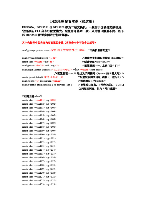
DES3550配置实例(楼道用)DES3026、DES3550与DES3626都为二层交换机,一般作小区楼道交换机用,它们都是CLI命令行配置模式,配置命令基本一致,只是端口数量不同。
以下以DES3550配置实例进行标注解释。
其中尖括号中的内容为要配置的参数(实际命令中不包含尖括号)config snmp system_name <YW-1603-FTSCH-ZL-H11100> /*交换机名称配置*/config vlan default delete <1-48>/*删除交换机端口的默认vlan端口*/ create vlan <vlan33> tag <33>/*创建管理vlan vlan33*/config vlan <vlan33> add tag <1>/*配置管理vlan, 上联口为1口*/ config ipif System ipaddress <172.18.37.98/27> vlan<vlan33> state enable/*配置管理vlan IP地址及子网掩码(System的S需大写)*/ create iprout default <172.18.37.97 1> /*配置默认网关地址跳数(一般为1)*/ config ports <1> description <uplink> /*描述端口1为uplink*/config traffic_segmentation 2-48 forward_list 1 /*配置端口隔离。
1号为上联口,2-28口之间相互隔离,仅与1号口连通*//*创建业务vlan*/create vlan <vlan101> tag <101>create vlan <vlan102> tag <102>create vlan <vlan103> tag <103>create vlan <vlan104> tag <104>create vlan <vlan105> tag <105>create vlan <vlan106> tag <106>create vlan <vlan107> tag <107>create vlan <vlan108> tag <108>create vlan <vlan109> tag <109>create vlan <vlan110> tag <110>create vlan <vlan111> tag <111>create vlan <vlan112> tag <112>create vlan <vlan113> tag <113>create vlan <vlan114> tag <114>create vlan <vlan115> tag <115>create vlan <vlan116> tag <116>create vlan <vlan117> tag <117>create vlan <vlan118> tag <118>create vlan <vlan119> tag <119>create vlan <vlan120> tag <120>create vlan <vlan121> tag <121>create vlan <vlan122> tag <122>create vlan <vlan123> tag <123>create vlan <vlan124> tag <124> create vlan <vlan125> tag <125> create vlan <vlan126> tag <126> create vlan <vlan127> tag <127> create vlan <vlan128> tag <128> create vlan <vlan129> tag <129> create vlan <vlan130> tag <130> create vlan <vlan131> tag <131> create vlan <vlan132> tag <132> create vlan <vlan133> tag <133> create vlan <vlan134> tag <134> create vlan <vlan135> tag <135> create vlan <vlan136> tag <136> create vlan <vlan137> tag <137> create vlan <vlan138> tag <138> create vlan <vlan139> tag <139> create vlan <vlan140> tag <140> create vlan <vlan141> tag <141> create vlan <vlan142> tag <142> create vlan <vlan143> tag <143> create vlan <vlan144> tag <144> create vlan <vlan145> tag <145> create vlan <vlan146> tag <146> create vlan <vlan147> tag <147> create vlan <vlan148> tag <148>/*为每个端口配置不同的端口*/ config vlan <vlan102>add untag <2> config vlan <vlan103> add untag <3> config vlan <vlan104> add untag <4> config vlan <vlan105> add untag <5> config vlan <vlan106> add untag <6> config vlan <vlan107> add untag <7> config vlan <vlan108> add untag <8> config vlan <vlan109> add untag <9> config vlan <vlan110> add untag <10> config vlan <vlan111> add untag <11> config vlan <vlan112> add untag <12> config vlan <vlan113> add untag <13> config vlan <vlan114> add untag <14> config vlan <vlan115> add untag <15> config vlan <vlan116> add untag <16> config vlan <vlan117> add untag <17> config vlan <vlan118> add untag <18>config vlan <vlan119> add untag <19> config vlan <vlan120> add untag <20> config vlan <vlan121> add untag <21> config vlan <vlan122> add untag <22> config vlan <vlan123> add untag <23> config vlan <vlan124> add untag <24> config vlan <vlan125> add untag <25> config vlan <vlan126> add untag <26> config vlan <vlan127> add untag <27> config vlan <vlan128> add untag <28> config vlan <vlan129> add untag <29> config vlan <vlan130> add untag <30> config vlan <vlan131> add untag <31> config vlan <vlan132> add untag <32> config vlan <vlan133> add untag <33> config vlan <vlan134> add untag <34> config vlan <vlan135> add untag <35> config vlan <vlan136> add untag <36> config vlan <vlan137> add untag <37> config vlan <vlan138> add untag <38> config vlan <vlan139> add untag <39> config vlan <vlan140> add untag <40> config vlan <vlan141> add untag <41> config vlan <vlan142> add untag <42> config vlan <vlan143> add untag <43> config vlan <vlan144> add untag <44> config vlan <vlan145> add untag <45> config vlan <vlan146> add untag <46> config vlan <vlan147> add untag <47> config vlan <vlan148> add untag <48>/*配置每个vlan的1口为上联口*/ config vlan <vlan102> add tag <1> config vlan <vlan103> add tag <1> config vlan <vlan104> add tag <1> config vlan <vlan105> add tag <1> config vlan <vlan106> add tag <1> config vlan <vlan107> add tag <1> config vlan <vlan108> add tag <1> config vlan <vlan109> add tag <1> config vlan <vlan110> add tag <1> config vlan <vlan111> add tag <1> config vlan <vlan112> add tag <1>config vlan <vlan113> add tag <1>config vlan <vlan114> add tag <1>config vlan <vlan115> add tag <1>config vlan <vlan116> add tag <1>config vlan <vlan117> add tag <1>config vlan <vlan118> add tag <1>config vlan <vlan119> add tag <1>config vlan <vlan120> add tag <1>config vlan <vlan121> add tag <1>config vlan <vlan122> add tag <1>config vlan <vlan123> add tag <1>config vlan <vlan124> add tag <1>config vlan <vlan125> add tag <1>config vlan <vlan126> add tag <1>config vlan <vlan127> add tag <1>config vlan <vlan128> add tag <1>config vlan <vlan129> add tag <1>config vlan <vlan130> add tag <1>config vlan <vlan131> add tag <1>config vlan <vlan132> add tag <1>config vlan <vlan133> add tag <1>config vlan <vlan134> add tag <1>config vlan <vlan135> add tag <1>config vlan <vlan136> add tag <1>config vlan <vlan137> add tag <1>config vlan <vlan138> add tag <1>config vlan <vlan139> add tag <1>config vlan <vlan140> add tag <1>config vlan <vlan141> add tag <1>config vlan <vlan142> add tag <1>config vlan <vlan143> add tag <1>config vlan <vlan144> add tag <1>config vlan <vlan145> add tag <1>config vlan <vlan146> add tag <1>config vlan <vlan147> add tag <1>config vlan <vlan148> add tag <1>/*配置snmp网管*/删除系统默认的public(ro)、private(rw)字符串,指定合法的字符串(rw)DHS-3618:4#delete snmp community publicDHS-3618:4#delete snmp community privateDHS-3618:4#create snmp community <合法字符串>view CommunityView <read_write |readonly >/*配置telnet和console*/设置超级用户aaa,并设置口令为bbbDHS-3618:4#create account admin <aaa>Command: create account admin <aaa>Enter a case-sensitive new password: <bbb>Enter the new password again for confirmation: <bbb>删除用户aaaDHS-3618:4#delete account <aaa>Command: delete account aaa在系统提示Are you sure to delete the last administrator account?(y/n) 时回答y。
CISCO3550交换机配置DHCP服务器实例网络知识 电脑资料
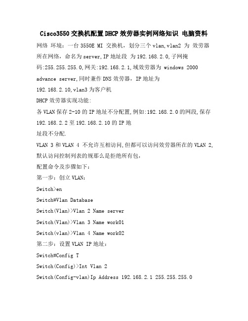
Cisco3550交换机配置DHCP效劳器实例网络知识电脑资料网络环境:一台3550E MI 交换机,划分三个vlan,vlan2 为效劳器所在网络,命名为server,IP地址段为192.168.2.0,子网掩码:255.255.255.0,网关:192.168.2.1,域效劳器为 windows 2000 advance server,同时兼作DNS效劳器,IP地址为192.168.2.10,vlan3为客户机DHCP效劳器实现功能:各VLAN保存2-10的IP地址不分配置,例如:192.168.2.0的网段,保存192.168.2.2至192.168.2.10的IP地址段不分配.VLAN 3和VLAN 4 不允许互相访问,但都可以访问效劳器所在的VLAN 2, 默认访问控制列表的规那么是拒绝所有包,配置命令及步骤如下:第一步:创立VLAN:Switch>enSwitch#Vlan DatabaseSwitch(Vlan)>Vlan 2 Name serverSwitch(Vlan)>Vlan 3 Name work01Switch(vlan)>Vlan 4 Name work02第二步:设置VLAN IP地址:Switch#Config TSwitch(Config)>Int Vlan 2Switch(Config-vlan)Ip Address 192.168.2.1 255.255.255.0Switch(Config-vlan)No ShutSwitch(Config-vlan)>Int Vlan 3Switch(Config-vlan)Ip Address 192.168.3.1 255.255.255.0 Switch(Config-vlan)No ShutSwitch(Config-vlan)>Int Vlan 4Switch(Config-vlan)Ip Address 192.168.4.1 255.255.255.0 Switch(Config-vlan)No ShutSwitch(Config-vlan)Exit/*注意:由于此时没有将端口分配置到VLAN2,3,4,所以各VLAN会DOWN掉,待将端口分配到各VLAN后,VLAN会起来*/第三步:设置端口全局参数Switch(Config)Interface Range Fa 0/1 - 24Switch(Config-if-range)Spanning-tree Portfast第四步:将端口添加到VLAN2,3,4中/*将端口1-8添加到VLAN 2*/Switch(Config)Interface Range Fa 0/1 - 8Switch(Config-if-range)Switchport Aess Vlan 2/*将端口9-16添加到VLAN 3*/Switch(Config)Interface Range Fa 0/9 - 16Switch(Config-if-range)Switchport Aess Vlan 3/*将端口17-24添加到VLAN 4*/Switch(Config)Interface Range Fa 0/17 - 24Switch(Config-if-range)Switchport Aess Vlan 4Switch(Config-if-range)Exit/*经过这一步后,各VLAN会起来*/第五步:配置3550作为DHCP效劳器/*VLAN 2可用地址池和相应参数的配置,有几个VLAN要设几个地址池*/Switch(Config)Ip Dhcp Pool Test01/*设置可分配的子网*/Switch(Config-pool)Network 192.168.2.0 255.255.255.0/*设置DNS效劳器*/Switch(Config-pool)Dns-server 192.168.2.10/*设置该子网的网关*/Switch(Config-pool)Default-router 192.168.2.1/*配置VLAN 3所用的地址池和相应参数*/Switch(Config)Ip Dhcp Pool Test02Switch(Config-pool)Network 192.168.3.0 255.255.255.0Switch(Config-pool)Dns-server 192.168.2.10Switch(Config-pool)Default-router 192.168.3.1/*配置VLAN 4所用的地址池和相应参数*/Switch(Config)Ip Dhcp Pool Test03Switch(Config-pool)Network 192.168.4.0 255.255.255.0Switch(Config-pool)Dns-server 192.168.2.10Switch(Config-pool)Default-router 192.168.4.1第六步:设置DHCP保存不分配的地址Switch(Config)Ip Dhcp Excluded-address 192.168.2.2192.168.2.10Switch(Config)Ip Dhcp Excluded-address 192.168.3.2192.168.3.10Switch(Config)Ip Dhcp Excluded-address 192.168.4.2192.168.4.10第七步:启用路由/*路由启用后,各VLAN间主机可互相访问*/Switch(Config)Ip Routing第八步:配置访问控制列表Switch(Config)aess-list 103 permit ip 192.168.2.0 0.0.0.255 192.168.3.0 0.0.0.255Switch(Config)aess-list 103 permit ip 192.168.3.0 0.0.0.255 192.168.2.0 0.0.0.255Switch(Config)aess-list 103 permit udp any any eq bootpc Switch(Config)aess-list 103 permit udp any any eq tftp Switch(Config)aess-list 103 permit udp any eq bootpc any Switch(Config)aess-list 103 permit udp any eq tftp any Switch(Config)aess-list 104 permit ip 192.168.2.0 0.0.0.255 192.168.4.0 0.0.0.255Switch(Config)aess-list 104 permit ip 192.168.4.0 0.0.0.255 192.168.2.0 0.0.0.255Switch(Config)aess-list 104 permit udp any eq tftp any Switch(Config)aess-list 104 permit udp any eq bootpc any Switch(Config)aess-list 104 permit udp any eq bootpc any Switch(Config)aess-list 104 permit udp any eq tftp any第九步:应用访问控制列表/*将访问控制列表应用到VLAN 3和VLAN 4,VLAN 2不需要*/ Switch(Config)Int Vlan 3Switch(Config-vlan)ip aess-group 103 outSwitch(Config-vlan)Int Vlan 4Switch(Config-vlan)ip aess-group 104 out第十步:结束并保存配置Switch(Config-vlan)EndSwitch#Copy Run Start原文转自:.ltesting.模板,内容仅供参考。
思科交换机3550配置手册(修改后)
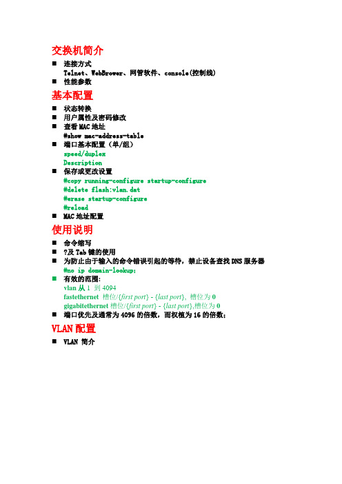
交换机简介⏹连接方式Telnet、WebBrower、网管软件、console(控制线)⏹性能参数基本配置⏹状态转换⏹用户属性及密码修改⏹查看MAC地址#show mac-address-table⏹端口基本配置(单/组)speed/duplexDescription⏹保存或更改设置#copy running-configure startup-configure#delete flash:vlan.dat#erase startup-configure#reload⏹MAC地址配置使用说明⏹命令缩写⏹?及Tab键的使用⏹为防止由于输入的命令错误引起的等待,禁止设备查找DNS服务器#no ip domain-lookup;⏹有效的范围:vlan从1 到4094fastethernet槽位/{first port} - {last port}, 槽位为0gigabitethernet槽位/{first port} - {last port},槽位为0⏹端口优先及通常为4096的倍数,而权植为16的倍数;VLAN配置⏹VLAN 简介⏹创建VLAN(基于静态端口)新建划分端口⏹查看VLAN配置⏹删除VLAN⏹问题:物理端口与可支持VLAN数目不相匹配;⏹命令行:switch>enswitch #vlan database //新建Vlan1switch (vlan)vlan 1name VLAN1switch #configure terminalswitch (config)int g0/1 //划分端口g0/1switch(config-if)switch mode accessswitch(config-if)switch access vlan 1TRUNK设置⏹TRUNK简介⏹数据封装类型dot1islnegotiate⏹配置trunk⏹定义trunk允许通过的vlan switch trunk allowed vlan …⏹Native vlan 意义及更改(如果trunk链路两端的native vlan不一致时,交换机将会报错)⏹DTP简介对于CISCO交换机之间的链路是否形成TRUNK,可以通过DTP(Dynamic Trunk Protocol)进行协商。
Cisco 3550速率限制的详细配置过程

Cisco 3550速率限制的详细配置过程 一、网络说明 PC1接在Cisco3550 F0/1上,速率为1M; PC1接在Cisco3550 F0/2上,速率为2M; Cisco3550的G0/1为出口。
二、详细配置过程 注:每个接口每个方向只支持一个策略;一个策略可以用于多个接口。
因此所有PC的下载速率的限制都应该定义在同一个策略(在本例子当中为policy-map user-down),而PC不同速率的区分是在Class-map分别定义。
1、在交换机上启动QOS Switch(config)#mls qos //在交换机上启动QOS 2、分别定义PC1(10.10.1.1)和PC2(10.10.2.1)访问控制列表 Switch(config)#access-list 10 permit 10.10.1.0 0.0.0.255 //控制pc1上行流量 Switch(config)#access-list 100 permit any 10.10.1.0 0.0.0.255 //控制pc1下行流量 Switch(config)#access-list 11 permit 10.10.2.0 0.0.0.255 //控制pc2上行流量 Switch(config)#access-list 111 permit any 10.10.2.0 0.0.0.255 //控制pc2下行流量 3、定义类,并和上面定义的访问控制列表绑定 Switch(config)# class-map user1-up //定义PC1上行的类,并绑定访问列表10 Switch(config-cmap)# match access-group 10 Switch(config-cmap)# exit Switch(config)# class-map user2-up Switch(config-cmap)# match access-group 11 //定义PC2上行的类,并绑定访问列表10 Switch(config-cmap)# exit Switch(config)# class-map user1-down Switch(config-cmap)# match access-group 100 //定义PC1下行的类,并绑定访问列表100 Switch(config-cmap)# exit Switch(config)# class-map user2-down Switch(config-cmap)# match access-group 111 //定义PC2下行的类,并绑定访问列表111 Switch(config-cmap)# exit 4、定义策略,把上面定义的类绑定到该策略 Switch(config)# policy-map user1-up //定义PC1上行的速率为1M Switch(config-pmap)# class user1-up Switch(config-pmap-c)# trust dscp Switch(config-pmap-c)# police 1024000 1024000 exceed-action drop Switch(config)# policy-map user2-up //定义PC2上行的速率为2M Switch(config-pmap)# class user2-up Switch(config-pmap-c)# trust dscp Switch(config-pmap-c)# police 2048000 1024000 exceed-action drop Switch(config)# policy-map user-down Switch(config-pmap)# class user1-down Switch(config-pmap-c)# trust dscp Switch(config-pmap-c)# police 1024000 1024000 exceed-action drop Switch(config-pmap-c)# exit Switch(config-pmap)# class user2-down Switch(config-pmap-c)# trust dscp Switch(config-pmap-c)# police 2048000 1024000 exceed-action drop Switch(config-pmap-c)# exit 5、在接口上运用策略 Switch(config)# interface f0/1 Switch(config-if)# service-policy input user1-up Switch(config)# interface f0/2 Switch(config-if)# service-policy input user2-up Switch(config)# interface g0/1 Switch(config-if)# service-policy input user-down。
Cisco3550的配置命令手册
Cisco3550的配置命令手册为了使两个或多个交换机在同一个MST区域,你必须有相同的VLAN到实例映射,相同的配置修正号,和相同的名字。
从特权模式开始,跟着这些步骤指派MST区域配置和启用MSTP。
这个过程是必需的。
命令目的Step 1 configure terminal 进入全局配置模式Step 2 spanning-tree mst configuration 进入MST配置模式Step 3 instance instance-id vlan vlan-range 映射VLAN到一个MST实例对于instance-id, 范围从1到15。
对于vlan vlan-range, 范围从1到4094。
当你映射一个VLAN到MST实例, 映射增大, 并且被指定的VLAN 范围被增加或被移动到现有的一个实例当中。
为了指定一个范围, 使用一个连字号;例如, instance 1 vlan 1-63 映射VLAN1至63到MST实例1。
为指定一个系列, 使用一个逗号;例如, instance 1 vlan 10, 20, 30 映射VLAN10,20,和30到MST 实例1.Step 4 name name 指定配置名。
该name 字符串有最大32个字符串并区分大小写。
Step 5 revision version 指定配置修订号数字. 范围是0到65535.Step 6 show pending 显示等待配置来确认你的配置Step 7 exit 应用所有改变, 并返回到全局配置模式.Step 8 spanning-tree mode mst 起用MSTP。
RSTP 也被启用。
注意改变生成树模式会中断流量,因为所有以前的生成树实例被停止,并启用一个新的生成树实例。
在同一时间,你不能同时运行MSTP和PVSTStep 9 end 返回特权模式Step 10 show running-config 确认你的条目Step 11 copy running-config startup-config (可选)在配置文件中保存你的条目为了返回缺省MST区域配置,使用命令:(global) no spanning-tree mst configuration为了返回缺省VLAN实例映射,使用命令:(config-mst) no instance instance-id [vlan vlan-range]为了返回缺省名,使用命令:(config-mst) no name为了返回缺省修正号,使用命令:(config-mst) no revision为了重新启用PVST,使用命令:(config) spanning-tree mode pvst这个例子显示怎样进入MST配置模式,映射VLAN10-20进入MST实例1,命名区域region1,设置配置修正号1,显示挂起的配置,应用变化,并且返回全局配置模式:Switch(config)# spanning-tree mst configurationSwitch(config-mst)# instance 1 vlan 10-20Switch(config-mst)# name region1Switch(config-mst)# revision 1Switch(config-mst)# show pendingPending MST configurationName [region1]Revision 1Instance Vlans Mapped-------- ---------------------0 1-9,21-40941 10-20-------------------------------Switch(config-mst)# exitSwitch(config)#配置根交换机交换机为映射到他的VLANs保持一个生成树实例。
思科 Cisco 3550 交换机配置手册 配置教程
配置接口特性这一章详细说明交换机上的接口和描述怎么配置他们。
这章有以下这些内容:●理解接口类型●使用接口命令●配置二层接口●监控和维护第二层接口●配置第三从接口注意:需要完整的有关该章的语法和应用信息,请参考Catalyst 3550 Multilayer Switch Command Reference和Cisco IOS Interface Command Reference for Release 12.1.理解接口类型这个部分描述了不同的接口类型,以及其它章节所包括的详细配置这些接口的一些参考内容。
其他章节描述了物理接口特性的配置过程。
这部分包括:∙基于端口的VLAN (Port-Based VLANs)∙交换端口(Switch Ports)∙以太网通道端口组(EtherChannel Port Groups)∙交换虚拟接口(Switch Virtual Interfaces)∙被路由端口(Routed Ports)∙连接接口(Connecting Interfaces)基于端口的VLAN (Port-based Vlans)一个Vlan是一个按功能、组、或者应用被逻辑分段的交换网络,并不考虑使用者的物理位置。
要更多关于Vlan的信息请看“Configuring VLANS”。
一个端口上接受到的包被发往属于同一个Vlan的接收端口。
没有一个第三层的设备路由Vlan间的流量,不同Vlan的网络设备无法通讯。
为了配置普通范围(Normal-range) Vlan(Vlan IDs 1-1005),使用命令:config-vlan模式(global) vlan vlan-id或vlan-configuration模式(exec) vlan database针对Vlan ID 1-1005的vlan-configration模式被保存在vlan数据库中。
为配置扩展范围(extended-range) Vlans (Vlan ID 1006-4094),你必须使用config-vlan模式,并把VTP的模式设为transparent透明模式。
- 1、下载文档前请自行甄别文档内容的完整性,平台不提供额外的编辑、内容补充、找答案等附加服务。
- 2、"仅部分预览"的文档,不可在线预览部分如存在完整性等问题,可反馈申请退款(可完整预览的文档不适用该条件!)。
- 3、如文档侵犯您的权益,请联系客服反馈,我们会尽快为您处理(人工客服工作时间:9:00-18:30)。
3550交换机(EMI)简明配置维护手册中望商业机器公司2002-12-10目录说明 (3)产品特性 (3)配置端口 (4)配置一组端口 (4)配置二层端口 (6)配置端口速率及双工模式 (6)端口描述 (7)配置三层口 (8)监控及维护端口 (10)监控端口和控制器的状态 (10)刷新、重置端口及计数器 (12)关闭和打开端口 (13)配置VLAN (14)理解VLAN (14)可支持的VLAN (15)配置正常范围的VLAN (15)生成、修改以太网VLAN (15)删除VLAN (17)将端口分配给一个VLAN (18)配置VLAN Trunks (19)使用STP实现负载均衡 (22)说明本手册只包括日常使用的有关命令及特性,其它未涉及的命令及特性请参考英文的详细配置手册。
产品特性3550EMI是支持二层、三层功能(EMI)的交换机支持VLAN∙到1005 个VLAN∙支持VLAN ID从1到4094(IEEE 802.1Q 标准)∙支持ISL及IEEE 802.1Q封装安全∙支持IOS标准的密码保护∙静态MAC地址映射∙标准及扩展的访问列表支持,对于路由端口支持入出双向的访问列表,对于二层端口支持入的访问列表∙支持基于VLAN的访问列表3层支持(需要多层交换的IOS)∙HSRP∙IP路由协议o RIP versions 1 and 2o OSPFo IGRP及EIGRPo BGP Version 4监视∙交换机LED指示端口状态∙SPAN及远端SPAN (RSPAN) 可以监视任何端口或VLAN的流量∙内置支持四组的RMON监控功能(历史、统计、告警及事件)∙Syslog功能其它功能:支持以下的GBIC模块:∙1000BASE-T GBIC: 铜线最长100 m∙1000BASE-SX GBIC: 光纤最长1804 feet (550 m)∙1000BASE-LX/LH GBIC: 光纤最长32,808 feet (6 miles or 10 km)∙1000BASE-ZX GBIC: 光纤最长328,084 feet (62 miles or 100 km) 配置端口配置一组端口当使用interface range命令时有如下的规则:∙有效的组范围:o vlan从1 到4094o fastethernet槽位/{first port} - {last port}, 槽位为0o gigabitethernet槽位/{first port} - {last port},槽位为0o port-channel port-channel-number - port-channel-number, port-channel号从1到64∙端口号之间需要加入空格,如:interface range fastethernet 0/1 – 5是有效的,而interface range fastethernet 0/1-5是无效的.∙interface range命令只能配置已经存在的interface vlan∙所有在同一组的端口必须是相同类别的。
见以下例子:Switch# configure terminalSwitch(config)# interface range fastethernet0/1 - 5Switch(config-if-range)# no shutdownSwitch(config-if-range)#*Oct 6 08:24:35: %LINK-3-UPDOWN: Interface FastEthernet0/1, changed state to up*Oct 6 08:24:35: %LINK-3-UPDOWN: Interface FastEthernet0/2, changed state to up*Oct 6 08:24:35: %LINK-3-UPDOWN: Interface FastEthernet0/3, changed state to up*Oct 6 08:24:35: %LINK-3-UPDOWN: Interface FastEthernet0/4, changed state to up*Oct 6 08:24:35: %LINK-3-UPDOWN: Interface FastEthernet0/5, changed state to up*Oct 6 08:24:36: %LINEPROTO-5-UPDOWN: Line protocol on Interface FastEthernet0/05, changed state to up*Oct 6 08:24:36: %LINEPROTO-5-UPDOWN: Line protocol on Interface FastEthernet0/3, changedstate to up*Oct 6 08:24:36: %LINEPROTO-5-UPDOWN: Line protocol on Interface FastEthernet0/4, changedstate to up以下的例子显示使用句号来配置不同类型端口的组:Switch# configure terminalSwitch(config)# interface range fastethernet0/1 - 3, gigabitethernet0/1 - 2Switch(config-if-range)# no shutdownSwitch(config-if-range)#*Oct 6 08:29:28: %LINK-3-UPDOWN: Interface FastEthernet0/1, changed state to up*Oct 6 08:29:28: %LINK-3-UPDOWN: Interface FastEthernet0/2, changed state to up*Oct 6 08:29:28: %LINK-3-UPDOWN: Interface FastEthernet0/3, changed state to up*Oct 6 08:29:28: %LINK-3-UPDOWN: Interface GigabitEthernet0/1, changed state to up *Oct 6 08:29:28: %LINK-3-UPDOWN: Interface GigabitEthernet0/2, changed state to up *Oct 6 08:29:29: %LINEPROTO-5-UPDOWN: Line protocol on Interface GigabitEthernet0/ 1, changed state to up*Oct 6 08:29:29: %LINEPROTO-5-UPDOWN: Line protocol on Interface FastEthernet0/ 2, changed state to up*Oct 6 08:29:29: %LINEPROTO-5-UPDOWN: Line protocol on Interface FastEthernet0/ 3, changed state to up配置二层端口3550的所有端口缺省的端口都是二层口,如果此端口已经配置成三层端口的话,则需要用switchport来使其成为二层端口。
配置端口速率及双工模式可以配置快速以太口的速率为10/100Mbps及千兆以太口的速率为10/100/1000-Mbps; 但对于GBIC端口则不能配置速率及双工模式,有时可以配置nonegotiate,当需要联接不支持自适应的其它千兆端口时Switch# configure terminalSwitch(config)# interface fastethernet0/3 Switch(config-if)# speed 10Switch(config-if)# duplex half端口描述Use the no description interface configuration command to delete the description.This example shows how to add a description on Fast Ethernet interface 0/4 and to verify the description:Switch# config terminalEnter configuration commands, one per line. End with CNTL/Z.Switch(config)# interface fastethernet0/4Switch(config-if)# description Connects to MarketingSwitch(config-if)# endSwitch# show interfaces fastethernet0/4 descriptionInterface Status Protocol DescriptionFa0/4 up down Connects to Marketing配置三层口Catalyst 3550支持三种类型的三层端口:SVIs: 即interface vlanNote当生成一个interface Vlan时,只有当把某一物理端口分配给它时才能被激活∙三层以太网通道口(EtherChannel)∙.路由口:路由口是指某一物理端口在端口配置状态下用no switchport命令生成的端口所有的三层都需要IP地址以实现路由交换配置步骤如下:配置举例如下:Switch# configure terminalEnter configuration commands, one per line. End with CNTL/Z. Switch(config)# interface gigabitethernet0/2Switch(config-if)# no switchportSwitch(config-if)# ip address 192.20.135.21 255.255.255.0Switch(config-if)# no shutdownSwitch(config-if)# endshow ip interface命令:Switch# show ip interface gigabitethernet0/2GigabitEthernet0/2 is up, line protocol is upInternet address is 192.20.135.21/24Broadcast address is 255.255.255.255Address determined by setup commandMTU is 1500 bytesHelper address is not setDirected broadcast forwarding is disabled<output truncated>监控及维护端口监控端口和控制器的状态主要命令见下表:举例如下:Switch# show interfaces statusPort Name Status Vlan Duplex Speed TypeGi0/1 connected routed a-full a-100 10/100/1000Base TXGi0/2 wce server 20.20.2 disabled routed auto auto 10/100/1000Base TX Gi0/3 ip wccp web-cache notconnect routed auto auto 10/100/1000Base TX Gi0/4 notconnect routed auto auto 10/100/1000Base TX Gi0/5 notconnect routed auto auto 10/100/1000Base TX Gi0/6 disabled routed auto auto 10/100/1000Base TX Gi0/7 disabled routed auto auto 10/100/1000Base TX Gi0/8 disabled routed auto 100 10/100/1000Base TX Gi0/9 notconnect routed auto auto 10/100/1000Base TX Gi0/10 notconnect routed auto auto 10/100/1000Base TX Gi0/11 disabled routed auto auto unknownGi0/12 notconnect routed auto auto unknownSwitch# show interfaces fastethernet 0/1 switchportName: Fa0/1Switchport: EnabledAdministrative Mode: static accessOperational Mode: downAdministrative Trunking Encapsulation: dot1q Negotiation of Trunking: OffAccess Mode VLAN: 1 (default)Trunking Native Mode VLAN: 1 (default)Trunking VLANs Enabled: ALLPruning VLANs Enabled: 2-1001Protected: falseUnknown unicast blocked: disabledUnknown multicast blocked: disabledVoice VLAN: dot1p (Inactive)Appliance trust: 5Switch# show running-config interface fastethernet0/2 Building configuration...Current configuration : 131 bytes!interface FastEthernet0/2switchport mode accessswitchport protectedno ip addressmls qos cos 7mls qos cos overrideend刷新、重置端口及计数器Note clear counters 命令只清除用show interface所显示的计数,不影响用snmp得到的计数举例如下:Switch# clear counters fastethernet0/5Clear "show interface" counters on this interface [confirm] ySwitch#*Sep 30 08:42:55: %CLEAR-5-COUNTERS: Clear counter on interface FastEthernet0/5by vty1 (171.69.115.10)可使用clear interface或clear line命令来清除或重置某一端口或串口,在大部分情况下并不需要这样做:Switch# clear interface fastethernet0/5关闭和打开端口使用no shutdown命令重新打开端口.举例如下:Switch# configure terminalSwitch(config)# interface fastethernet0/5Switch(config-if)# shutdownSwitch(config-if)#*Sep 30 08:33:47: %LINK-5-CHANGED: Interface FastEthernet0/5, changed state to a administratively downSwitch# configure terminalSwitch(config)# interface fastethernet0/5Switch(config-if)# no shutdownSwitch(config-if)#*Sep 30 08:36:00: %LINK-3-UPDOWN: Interface FastEthernet0/5, changed state to up 配置VLAN理解VLAN一个VLAN就是一个交换网,其逻辑上按功能、项目、应用来分而不必考虑用户的物理位置。