MTS传感器
MTS性能试验台传感器标定(校准)方法

MTS标定教案(Calibration)-----张越201605121、打开MTS站管理器:Station Manager;2、打开操作权限设置框内下拉箭头,更换操作权限为:calibaration(权限密码:calibration);3、打开菜单栏显示选项(Display),从下拉菜单中选择站设置(Station Setup),再从打开的站设置(Station Setup)对话框中选择辅助输入(Auxilialy input)中Load选项;4、在calibration标签中,根据标准传感器拉压数据调整POST-AMP和Delta K参数:前级放大(Pre-amp):调理器前级增益(粗放)。
后级放大(Post-amp):调理器前级增益。
(细放)。
总增益(Total Gain):调理器前级增益(粗放)与调理器前级增益(粗放)的乘积。
调偏系数(Delta K):应用调偏系数到传感器输出信号。
调偏系数是一个只影响传感器正向输出的增益控制。
由于传感器出厂时存在不对称,调偏系数可以补偿这种不对称性。
具体操作过程:1)、在标准测力装置及MTS负荷传感器均不受拉压力时,分别通过station controls选择signal Auto offset,清除设备负荷传感器显示力值;通过标准测力装置仪表清零按键将仪表显示值清零。
2)、通过将标准测力装置上加压装置,现对标准传感器及MTS负荷传感器施加3次50N-80%满量程负荷来消除磁滞影响(注意3次施加压力或拉力过程中,减小的施加力不应使传感器显示反向过零)。
3)、通过标准测力装置施加压力至反向力值80%,待读数稳定后,对比标准测力仪表显示力值与MTS测试软件显示力值偏差,如有偏差通过后级放大(Post-amp)参数栏两边调节小三角按钮,将MTS显示力值校准到与标准测力仪表显示力值一致;4)、负向限校准完成,通过标准测力装置施加-100N、-200N、-300N、-500N、-1000N、-1500N直至满量程的80%,对比标准测力仪表和MTS测力软件显示力值误差是否满足要求,如不满足要求则重复以上过程;如满足要求则通过标准测力装置施加100N、200N、300N、500N、1000N、1500N直至满量程的80%,对比标准测力仪表和MTS测力软件显示力值误差是否满足要求,如满足要求则保存校准参数;5)、如不满足要求则:通过标准测力装置施加压力至正向力值80%,待读数稳定后,对比标准测力仪表显示力值与MTS测试软件显示力值偏差,如有偏差通过调偏系数(Delta K)参数栏两边调节小三角按钮,将MTS显示力值校准到与标准测力仪表显示力值一致。
美国mts位移传感器常见故障

美国MTS位移传感器常见故障直线的工作原理是跟滑动变阻器一样的,它作为分压器使用的,美国MTS位移传感器它是以相对的输出电压来呈现出所测量位置的实际上的位置。
对这个装置的工作有下面几点要求:1、如果电子尺已经使用很长时间了,而且密封已经老化,同时夹杂着很多杂质,而且水混合物和油会严重影响电刷的接触电阻的,这样会使显示的数字不停地跳动。
这个时候可以说直线位移传感器的电子尺已经损坏了,需要更换。
2、若电源的容量很小,就会出现很多情况的,所以,供电电源需要有充分的容量。
那么,容量不足,就会造成如下的情况:熔胶的运动会使合模电子尺的显示变换,有波动,或者合模的运动会使射胶电子尺的显示波动,造成测量结果误差很大。
如果电磁阀的驱动电源于直线位移传感器供电电源同时在一起的时候,更容易出现以上的情况,情况严重时用万用表的电压档甚至可以测量到电压的有关波动。
如果情况不是因为高频干扰、静电干扰或者是中性不够好的造成的,那么就有可能是电源的功率太小造成的。
3、调频干扰和静电干扰都有可能让直线位移传感器的电子尺的显示数字跳动的。
美国MTS位移传感器电子尺的信号线与设备的强电线路要分开线槽。
电子尺必须要强制性地使用接地支架,而且同时让电子尺的外壳跟地面良好地接触。
信号线需要使用屏蔽线,而且电箱的一段应该跟屏蔽线接地的。
如果有高频干扰的时候,通常使用万用表的电压测量就会显示正常,但是显示数字就是会跳动不停的;而出现静电干扰时,出现的情况也是跟高频干扰一样的。
要证明看是否是静电干扰时,可以先使用一段电源线把电子尺的封盖螺丝跟机器上的某一些的金属短接起来就可以了,只要一短接起来,静电干扰就会马上消除掉的。
但是如果要消除掉高频干扰就很难用上面的方法了,变频节电器和机器手都经常出现高频干扰的,所以可以试一下用停止高频节电器或者机械手的方法来验证是不是高频干扰的。
4、如果直线位移传感器的电子尺在工作的过程当中,在某一点的显示数据有规律地跳动,或者是没有显示数据的时候,出现这种情况就需要检查连接线绝缘是不是出现破损的现象,并且跟机器的外壳很有规律地接触而导致的对地短路。
MTS磁致伸缩位移传感器
模拟:50-1500MM IP65
模拟:50-1500MM
模拟:50-1000MM
-40℃...+75℃ 抗冲击:100g(单一冲击);抗震荡:10g(10-2000Hz)
TDU-200数字显示(用于数字脉冲输出);MK-292(并行24Bit二进制,BCD或格雷码)
北京冶自欧博科技发展有限公司
地址:北京市丰台区西四环南路 88 号
E-系列 一个经济型的传感器系列,为 用户提供简单、直接的位置反 馈信号,节省成本,提升生产 效益。输出模式有:模拟的电 压与电流、数字的 Start/Stop 和 PWM 脉冲等。 E- 系 列 提 供 多 元 化 的 安 装 方 式,最适合机床行业使用。
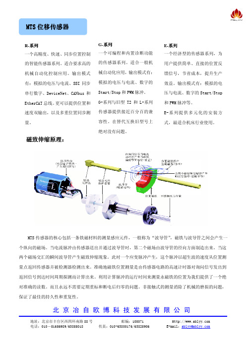
MTS 传感器的核心包括一条铁磁材料的测量感应元件,一般称为“波导管”,磁铁与波导管之间会产生一 个纵向的磁场。当电流脉冲由传感器送出并通过波导管时,第二个磁场由波导管的径向方面制造出来。当这 两个磁场交汇的瞬间波导管产生磁致伸缩现象。此时一个应变脉冲产生,这个脉冲以超生波的速度从位置测 量点返回传感器并被检测器检测出来。准确地磁铁位置测量是由传感器电路的高速计时器对询问信号发出到 返回信号到达时间周期探测而计算出来。利用计算脉冲的运行时间来测量永磁铁的位置为我们提供了一个绝 对准确的读数。而且永远不需要定期重标和断电后归零的问题。非接触式的测量消除了机械的磨损的问题, 保证了最佳的持久性和重复性。
EP铝成型外壳只能外置
ER缸体外壳
EP2
EH耐压不锈钢管
电压:0...10v; 10...0v;-10...+10V; +10...-10V 电流:0/4...20mA;20...4/0mASSI:串行同步接口总线:CANbus(2);DeviceNet Profibus DP;开始/停止或PWM
MTS技术优势
• 震荡频率 100HZ – 2000HZ • 加速度 19.2 gRMS • 峰值加速度 80g – 90g • 最大误差 80µm • 无信号丢失
MTS磁致伸缩技术优势 – 最高的防护等级
专利技术
MH/EH系列传感器密封可达IP69K
MTS磁致伸缩技术优势 – 双层电子屏蔽
来自于PLC或电源的干扰信号
电缆金属接头
基本电路
接口电路,EMI滤波
电缆屏蔽层
SSEE SShhiieelldd
应用电路
内部信号不受外来干扰信号的影响
-内部屏蔽层与外部屏蔽层完全绝缘,互相没有干扰. - 内部信号屏蔽层接信号地. - 外部屏蔽层接电源地和机器地
波导管屏蔽
耐压外管 内部屏蔽层 信号绝缘层 外部屏蔽层
MTS磁致伸缩技术优势
“一个系统很好地工作 ,高精度是关键”
MTS
波导管
Temposonics技术
• 维拉里转换器 – 将扭转转换成纵向信号
优点
• 更均质的波导管意味着更好的线性 • 扭转信号分解成纵向动作可以防止很高的冲击和震动 • 很高的信噪比意味着更好地阻止系统噪音和EMI ,无需后续放大
和调制电路
H=0 DL = Fractional Change L
磁致伸缩技术原理
机械应变脉冲
电流脉冲产生的磁场
位置磁铁产生的磁场
磁致伸缩感应元件(波导管)
应变脉冲转换器
询问电流脉冲
锻压技术交流会
MTS磁致伸缩技术原理 MTS传感器的技术优势
MTS磁致伸缩技术优势
非接触测量,绝对值输出,高质量,寿命长
正弦测试
IEC 68-2-6
关于美国MTS位移传感器工作原理及产品的6特点

关于美国MTS位移传感器工作原理及产品的6特点美国MTS位移传感器又称为线性传感器,把位移转换为电量的传感器。
位移传感器是一种属于金属感应的线性器件,传感器的作用是把各种被测物理量转换为电量它分为电感式位移传感器,电容式位移传感器,光电式位移传感器,超声波式位移传感器,霍尔式位移传感器。
美国MTS位移传感器工作原理1、电位器式位移传感器原理电位器式位移传感器,它通过电位器元件将机械位移转换成与之成线性或任意函数关系的电阻或电压输出。
普通直线电位器和圆形电位器都可分别用作直线位移和角位移传感器。
但是,为实现测量位移目的而设计的电位器,要求在位移变化和电阻变化之间有一个确定关系。
电位器式位移传感器的可动电刷与被测物体相连。
物体的位移引起电位器移动端的电阻变化。
阻值的变化量反映了位移的量值,阻值的增加还是减小则表明了位移的方向。
通常在电位器上通以电源电压,以把电阻变化转换为电压输出。
线绕式电位器由于其电刷移动时电阻以匝电阻为阶梯而变化,其输出特性亦呈阶梯形。
如果这种位移传感器在伺服系统中用作位移反馈元件,则过大的阶跃电压会引起系统振荡。
因此在电位器的制作中应尽量减小每匝的电阻值。
电位器式传感器的另一个主要缺点是易磨损。
它的优点是:结构简单,输出信号大,使用方便,价格低廉。
2、磁致伸缩位移传感器原理它主要是利用磁致伸缩原理、通过两个不同磁场相交产生一个应变脉冲信号来准确地测量位置的。
由于在之前的文章中,皮卡中国小编已经为大家介绍了磁致伸缩位移传感器原理,在这里就不做赘述了。
常见MTS位移传感器特点1、绕位移传感器它是将康铜丝或镍铬合金丝作为电阻体,并把它绕在绝缘骨架上制成。
绕线电位器特点是接触电阻小,精度高,温度系数小,其缺点是分辨力差,阻值偏低,高频特性差。
主要用作分压器、变阻器、仪器中调零和工作点等。
2、导电塑料位移传感器用特殊工艺将DAP(邻苯二甲酸二稀丙脂)电阻浆料覆在绝缘机体上,加热聚合成电阻膜,或将DAP电阻粉热塑压在绝缘基体的凹槽内形成的实心体作为电阻体。
MTS位移传感器与SM338

摘要我厂自2003年1月份工艺升级改造后,设备自动化控制向着高精尖方向发展,已达到国内同行业领先的水平.随之而来对我们维护人员的业务水平有了更高的要求,必须尽快熟悉新设备的性能、控制原理及工艺要求,以应维护的需要。
同时针对设备设计存在的缺陷及现场使用中暴露出的问题也有待技术人员组织攻关与处理,而其中技术与维护难点又集中在我厂四辊主轧区。
因此通过近两年的设备维护与管理,我带领本班组人员,结合自身优势和本专业特点,重点对四辊前后对中进行了系统维护工作。
结合设计图纸将原供电控制电源进行改造;通过现场调研在对中相关位置加了1个极限开关,使对中在一定位置进行减速减小设备的冲击负荷;结合MTS位移传感器与PLC 模块接口数据传输通讯特点,翻阅产品说明书和设备特点,增加编写相应对中实时位移检测程序,解决了对中实时检测开口度的问题,同时对中限位保护也为机械设备起到了至关重要的保护作用。
目录一、前言二、正文三、结论四、致谢五、参考资料一、前言:设备投入运行后,加强平时的学习与积累,通过对设备的不断熟悉及日常维护,故障的处理及结合图纸和程序的学习对本系统有了更深入的了解。
同时对设备系统本身存在的缺陷,本人结合图纸和调试厂家编写的PLC程序也做了大量的程序修改和完善工作。
其中原四辊对中主要缺陷有:原设计机前后对中+24V电源由一路控制电源供给,这样当机前或机后对中发生问题,需对其中一台对中进行故障处理或检修时,一停电源两部对中全部不能投入使用,给生产造成了停机时间,因此需对电源进行重新配电;原对中设计只有最小开口度和最大开口度两个限位开关,对中在运行中由于存在较大的惯性,给机械设备造成了较大的冲击,维修人员经常需对机械设备进行加固和调整,因此需对冲击问题进行解决;在轧钢中由于环境因素及调试问题造成比例板损害,我们根据工艺设计的要求及时调整比例放大板并由原来一套数字板加装一套模拟板,互为备用(加装切换闸),并将装置移到室内,解决了因环境及原板有问题带来的故停时间。
保护传感器测试系统 MTS-5100 说明书

MTS-5100Advanced Test Equipment Corp. 800-404-ATEC (2832)Protective Relay Test SystemAt a Glancefi tsSteady-state testingDynamic testing - step/ramp/state sequence Transient waveform testing GPS time synchronized testingDirect front panel interface for all functions Intuitive operationExceptional productivity for common tasks All-in-one, no options required Very high VA current output channels Realistic fault quantities and waveforms(Even under ordinary manual testing)Onboard memory + USB memory driveTransmission & Distribution: overcurrent, under/overvoltage, directional overcurrent, distance,frequency, line differential, transformer differential (1-phase, 3-phase), bus differential, capacitorprotection, out-of-step, synchrocheck, reclosing, breaker failure, lockout, time-delay, and auxiliary relaysGenerator Protection and Control: differential, loss-of-fi eld, under/overvoltage, overexcitation,stator ground, negative sequence, frequency, unbalance, reverse power, out-of-step, synchronizing, Synchro-check, lockout, time-delay, and auxiliary relaysIndustrial: overcurrent, under/overvoltage, transformer differential, bus differential, capacitor,overload, motor protection, lockout, time-delay, and auxiliary relaysOther: Current, Voltage, Watt, VAR, and Frequency transducers and meteringThe MTS-5100 Protective Relay Test SystemWhat Can It Do For You?The MTS-5100 is the most powerful all-in-one relay test system with a direct front panel interface for all functions, without exception! The ideal system for testing and calibrating protective relays using traditional test techniques or applying realistic power system simulations.Easily test single overcurrent relays to multi-terminal end-to-end schemes with this one box. No add-ons. No hidden costs. The MTS-5100 includes all the power (VA) that you need for old electromechanical relays in each output channel to minimize connection changes, with all of the output current and voltage channels you need for modern microprocessor-based relays. Powerful productivity functions and built-in intelligence make it a simple task to perform realistic power system simulations which increases productivity and effectiveness. You can even save your test results directly from the front panel to simplify your NERC/FERC reporting requirements.All the Necessary Output Channels and Inputs for Protectionand Control Relay Testing6 AC/DC Currents6x30Arms, 3x60Arms,1x180Arms4 AC/DC Voltages4x250Vrms, 1x750Vrms12 Contact / 0-250Vrms Voltage inputs4 Contact outputsTransducer voltage/inputUSB MemoryGPS inputIRIG inputIRIG outputIE C 61850310.4” screen! Larger thanmost tablet computers.fi nedBacklit display visible inthe brightest sunfi ngers! Low activationfi neVGA output for external monitoror projectorC 61850, computer control or5Be Productive the Very FirstDay Novices and veterans alike need help to keep up with the rapid advances in protection technology to contend with the complexities of testing today’s sophisticated relays and systems. In fact, a IEEE Power System Relaying Committee’s Survey on Relay Test Practices found that “most relay test personnel receive fewer than 16 hours of relay training per year.”* That’s why we started from scratch to create atruly “intuitive to use” relay test set, so that you’ll be productive from the very fi rst day. The MTS-5100 provides built-in intelligence to simplify its advanced testing capabilities and controls required for multipleinput and output channels. Here are a few examples:Relay test screens that simplify the testing of common relay types. Each screen is designed to get the jobdone in the fewest number of steps.You’ve tested differential relays before,but can you remember the formulaeand test connections for the differentconfi gurations?The MTS-5100 confi gures itself, drawspictures of the connections, lists theformulae, and calculates the results.Improve your effi ciency even more bysaving settings for often used tests rightin the built-in memory and recallingthem later. Use a USB memory deviceto use your test settings with anyMTS-5100.fi es single and 3-phase impedance Relay Specifi c Productivity ScreensImmediately Recall Saved Testsrestraint currents plus slopeBuilt-in confi gurations forcommon relays(BDD, HU, SEL-387, etc.)including relays withsix-current inputsBuilt-in confi gurations forstandard testsDifferential Test ScreenImpedance/Distance Test Screen7Many tests only require a simple single-phase or 3-phase injection. Just one button from the main screen is the manual test screen, where you can immediately energize the outputs and test the device. Phase sequence, amplitude and frequency automatically default to your pre-de fi ned system defaults.and fault phase angle, changing appropriate amplitude and phase anglefaults.Similarly, for 3-phase faults, changing the fault current, fault voltage and phase angle changes the outputs of all 3 phases simultaneously.For applications such as rate-of-change of frequency relays, motor bus transfer schemes, or simply automatic pickup testing, ramp one or all parameters directly from the front panel.For reclosing scheme testing or evolving faults, set up multi-state tests directly from the front panel.Single Button Access for Steady-State InjectionsRamping and State Sequencingparameters independently in any state breaker status signals, permissive signals, etc.durations and/or changes detected on input channels“High Va Output for Electromechanical Relays”The rest of the world may have gone all digital, but the truth is that it may be a decade or more before the installedbase of electromechanical relays is displaced by digital relays. Hence, the need for high power current outputs remains. The MTS-5100 deals with this reality head-on, with up to 900 VA per channel in 3-Phase mode! That is more VA capability than all other modern relay test sets.Don’t be fooled by VA comparisons between manufacturers. The highest burden E-M relays require h i g h c o m p l i a n c e v o l t a g e s and the MTS-5100 provides this. Paralleling channels on other test sets may increase available current, but it will not increase the output compliance voltage. Their low output compliance voltages will not be able to inject those higher currents into high burdens.For high set instantaneous elements, parallel all current channels for up to 0-180Arms with 2400 VA of single phase current with a single button press. Control the magnitude and phase angle of the paralleled group as if it were one channel on all other screens. Fast, simple, intuitive.How many of your relay panels still look like this?9“Realistic Output Waveforms Even When UsingTraditional (Manual) Test Methods”The exponentially decaying DC offset component of real-worldfault currents can be automatically generated by the MTS-5100.This ensures realistic test waveforms essential for testing today’shigh-speed, sub-cycle, line and bus protection relays. Evenelectromechanical relays, such as the Westinghouse KD, are knownto operate incorrectly in response to test currents high di/dt withoutoffset has also been identifigenerator protection and breaker failure protection relays.**panel. The fault inception angle has a signifiSimulating actual in-service conditions as closely as possible also includesaccounting for load. Failure to account for increasing load on the networkor the effects of load on protection operation has been shown to contribute toprotection system failure.** With the MTS-5100, the affect of load can beautomatically included with a single setting.The MTS-5100 automatically calculates realistic voltage and currentphasors without zero sequence components for phase faults. This isespecially important to properly test relays which employ zero sequenceimpedance or negative sequence impedance directional supervision,residual current supervision or sophisticated polarization and/or faultphase selection techniques.** Other test sets allow control of phase-phasevoltage and current to simulate phase faults, but often produce high zerosequence voltages not present in the real world that can prevent elementsfrom operating correctly. You only need to change one voltage, current,and angle value to ensure realistic outputs to realistically simulate the mostcommon faults to ensure correct element operation.** See /info.html for references to technical papers on these subjects.The North American Electric Reliability Council, (NERC) has emphasized time and again “The use of increasingly complex protection systems demands careful planning, contingency analysis, personnel training and ongoing review. … Protection systems should be tested with methods which mimic actual conditions as closely as possible”.** We have seen the growing application of transient testing of protective relays. Now you can get some of the benefi ts of realistic test waveforms, even when using traditional (manual) test methods, where others must resort to computer driven methods. Here are some examples:Automatic Current DC Offset & Controlled FaultInception AngleTrue Phase-Fault SimulationEasily Include the Affects of Load(30°IA inception angle)Affect of load automaticallyGPS synchronized end-to-end testing is a proven method for verifying communication assisted transmission protection schemes by employing GPS time code signals.* No other method can guarantee the absolute phase, frequency and time synchronization required, and the MTS-5100 has the integrated facilities to: Display and store waveformsBuilt-in, standard GPS receiverSequence of events recordingDon’t have Waveforms? The front panel controls andproductivity modes make it easy to create realistic faultsimulations with no computer required.11Channels are automatically assigned to COMTRADE fi le contents upon loading. Change if required.Save results to a fi leif desired for later referenceAfter the test executes, verify correct operation directly on the sequence of events graph or table.Don’t have a COMTRADE fi le? You can perform end-to-end testing from the manual test screen and create tests on the fl y or apply values supplied from the engineer. Use our E2E Settings File Generator to convert tests from spreadsheet or SS1 format to a MTS-51000 test fi le for easy conversion and playback.。
MTS位移传感器

MTS位移传感器信息来源:广州兰瑟电子科技公司MTS位移传感器简介利用非接触之科技监察着活动磁铁位移。
传感器本身输出讯号为绝对数值,电源突然中断,也不会影响数据,无须重新调整零位。
MTS位移传感器型号示例1. RHM0250MD601A01代表RH系列, M18X1.5螺纹, 250mm 行程公制, D60插头, 4-20mA输出2. RHM0250MP021V01代表RH系列, M18X1.5螺纹, 250mm 行程公制, 02米电缆, 0-10VDC输出3. LHMD600M06501A0代表LH系列, M18X1.5螺纹, D60插头, 公制,650mm 行程, 4-20mA输出4. LHMR002M06501V0代表LH系列, M18X1.5螺纹, 02米电缆, 公制, 650mm 行程, 0-10VDC输出5. EPS0500MD601A0 代表EP系列, 滑块磁铁, 500mm 行程公制, D60插头, 4-20mA输出6. LPRLAM03001代表LP系列, 推拉杆, 7呎电缆, 4-20mA输出, 公制行程300mm, 24V输入7. TTMRBM1500DE010代表TT系列, M18X1.5螺纹, RB插头, 公制, 1500mm行程, 数字输出每秒10次8. TTSROU0240AS1B代表TT系列, 3/4”-16UNF螺纹, 5呎电缆, 英制, 24吋行程, 模拟输出0-10VDC 平衡模式9. GHM0250MD601A01代表GH系列, M18X1.5螺纹, 250mm行程公制, D60插头, 4-20mA输出10. GHM0250MR021R01代表GH系列, M18X1.5螺纹, 250mm行程公制, 02米电缆, RS422(开始/停止)数字脉冲输出MTS位移传感器选项配件1. 磁环:13.5(内)X32.8(外)X7.9(厚), 型号:2015422. 垫片:14.3(内)X31.8(外)X3.2(厚), 型号:4006333. 插头:D60, D62, D63, D70, RG, RB, MS4. 电缆:5呎, 15呎, 25呎, 50呎, 100呎, 2米, 5米, 10米, 15米, 30米自定长度。
- 1、下载文档前请自行甄别文档内容的完整性,平台不提供额外的编辑、内容补充、找答案等附加服务。
- 2、"仅部分预览"的文档,不可在线预览部分如存在完整性等问题,可反馈申请退款(可完整预览的文档不适用该条件!)。
- 3、如文档侵犯您的权益,请联系客服反馈,我们会尽快为您处理(人工客服工作时间:9:00-18:30)。
美国MTS传感器、MTS位移传感器、MTS磁性传感器
上海富万国际贸易有限公司代理销售美国MTS传感器、MTS位移传感器、MTS磁性传感器、MTS磁性接近开关、MTS液位计、MTS接头、MTS磁环、MTS磁致伸缩位移传感器等等。
MTS传感器适用于高温、高压和强振荡等极其恶劣的工况,其绝对式输出很好地解决了断电归零问题,由于敏感元件都是非接触式、无磨损运行,平均无故障时间为23年,美国MTS系统公司是全球第一家开拓磁致伸缩测量技术的公司。
MTS位移传感器、MTS传感器,主要用于冶炼、轧钢系统地伺服液压缸连续位置测量和反馈,如在热连轧厂中利用MTS 位移传感器作液压AGC控制。
MTS磁性传感器是运用独特的电路设计和筛选技术,利用块状检出原件制造出的高敏感性传感器。
由于在受物体上安装磁石进行检测,使得传感器对复杂环境的耐受能力非常强。
同时可以根据客户的应用环境的不同,选择不同的磁石。
MTS 磁性接近开关专业用来代替机械型的接近开关,是具有非接触,长寿命,检测的距离范围大等特点的接近开关。
如被检测物体是磁性物质,即使在水,油污,粉尘等恶劣环境条件下,MTS磁性接近开关都可以准确无误的将检测磁石的位置检测出来。
同时,磁性接近开关之间互不干扰,可以并排使用。
型号有:MHS-1005,MHS-1008-V2,MHS-1043等。
MTS 高灵敏磁性传感器是由MTS自主研发的电路,秉承MTS一贯的偏移量,电压倾角和温度特性。
除了应用于无人驾驶搬运车,基于磁铁位置来进行控制的各种应用中都可以一显身手,常用于搬运台的移动检测、承物台的停止位置检测、无人搬运车的自动导航和架子位置的检测等。