Qsys_Workshop_FINAL_CN
同步轴控制模块1746-QS操作指南说明书

Quick Start Synchronized Axes Control Module (Catalog Number 1746-QS)Use this abbreviated procedure for getting the 1746-QS module into operation.The following software and documentation are available for download from our website:•User Manual for the Synchronized Axes Control Module, publication 1746-6.19•Hydraulic Configurator Software to set up, tune, and troubleshoot axis movement •Ladder Logic File of example logic to sequence module operation to the machineChapter references in this procedure refer to the user manual, publication 1746-6.19.In addition to the 1746-QS module, you must have (or purchase) the following:– PC with 4 MByte of available disk space– Interface Module (terminal blk) (1492-AIFMQS)*– Windows ’95™ operating system– Interface Module cable (1492-ACABLExxxQS)*– SLC 5/03 processor (or later) with M0/M1 files– Interface cable: PC to QS (1747-CP3)– Comm. Interface (1784-KTX) if using SLC 5/04– RSLogix500 Ladder Logic Software* Required for CE Certification. Otherwise, recommended for wiring convenience.at one end only b) LDT flange and machine frame c) IFM T erminal Block GND terminal 51 d) I/O chassisPublication 1746-10.3 – December 1997Synchronized Axes Control Module2Publication 1746-10.3 – December 1997We give you example LDT connections for a Temposonics II with differential inputs.Path to the Allen-Bradley website: extension to manual: /manuals (Application Systems Library, publication 1746-6.19)extension to Hydraulic Configurator and ladder logic : /mem/appsys/prodinfo/applac/appla/qssw/index.html Download manual, Hydraulic Configurator, and ladder logic to separate subdirectories in your hard drive.1.Connect the PC serial port (COM1) to the QS module’s 9-pin connector with a 1747-CP3 cable.You may run RSLogix500 and Hydraulic Configurator softwares if COM1 & 2 are both available,or if you provide a KTX card for DH+ connection to SLC processor with another 1747-CP3 cable.2.Open Hydraulic Configurator. Main screen appears. If also “No Motion Controller Detected”, thencheck the 1747-CP3 cable connection between PC and QS module, and/or go to step 3.3.Set Hydraulic Configurator COM port to match your PC. To do this, pull Monitor Options fromTools in the ToolBar. In the window, enter the COM port number you used in step 1.You can run Hydraulic Configurator of fline to access help screens, and view stored data and axis plots.1.Enter the type of LDT in the Configuration word.2.Determine the Of fset and Scale Parameters and the Extend and Retract Limits in open-loop mode.3.Determine the value of the Dead Band Eliminator.4.Tune each axis in closed-loop mode, independent of ladder logic.5.Save configuration parameters for each axis in SLC memory.We provide sample ladder programs to illustrate preferred methods of using the module.You may download them from our website and use them as a base for creating your own logic (step 3).1.Configure I/O for SLC processor: module slot number, ID = 13627, advance config M0 = M1 = 64.2.If using our logic, modify rungs and addresses to match your system.3.Integrate synchronized axes movement with ladder logic using status bits and command words.Allen-Bradley, a Rockwell Automation Business, has been helping its customers improveproductivity and quality for more than 90 years. We design, manufacture and support a broadrange of automation products worldwide. They include logic processors, power and motioncontrol devices, operator interfaces, sensors and a variety of software. Rockwell is one of theWorldwide representation。
Qsys_Lab_PCIe_FINAL_CN

PCIe Qsys研讨这一设计实例深入浅出,介绍怎样产生一个Qsys子系统。
您将产生一个含有以下组成的Qsys系统:∙在Cyclone IV GX收发器入门套件上,设计带嵌入式收发器的Gen1×1硬核IP的PCI Express IP 编译器。
∙片内RAM存储器∙模块化散射收集DMA控制器(MSGDMA) (位于lib路径中)图1显示了Qsys怎样集成PCI Express的IP编译器、片内SRAM,以及定制组件MSGDMA。
这一设计实例使用了一个DMA,这个DMA在片内存储器SRAM,和位于根复合模块(主机)侧的系统缓冲之间进行数据传送。
图1.Qsys生成的端点此次研讨对以下步骤进行了讲解:1.对设计进行准备,以进行编译2.建立一个Quartus II工程3.建立一个Qsys系统4.对PCI Express的IP编译器进行参数赋值5.将其他组件加入Qsys系统中6.完成Qsys中的链接7.设定导出接口8.设定地址分配9.生成Qsys系统10.编译设计11.对器件编程对设计进行准备,以进行编译设计准备进行编译时,请按照以下步骤进行:1. 如果您没有看到C:\<path>\Qsys_workshop\PCIe_Lab 路径含有表1中列出的以下文件夹和文件,请联系您的指导人员。
建立一个Quartus II 工程1. 在Quartus II 软件中,在File 菜单上,点击New Project Wizard 。
2. 在Introduction 页面的New Project Wizard 窗口中,点击Next 。
3. 在Directory, Name, Top Level Entity 页面中,输入以下信息(参见图2),点击Next 。
图2.新工程向导4. 在Add Files 页面中,点击Next 。
5. 在Family & Device Settings 页面中,对于器件系列,选择Cyclone IV GX ,点击Next 。
quartus ii 11中用Qsys点灯

2)添加 memory
3)jtag_uart 默认。
4)system ID
默认。 5)led
4、互联 clk50 的时钟输出连上,复位输出连上。默认连接。
3、编译运行
二、nios Nios 中与 sopc 下一样。 1、新建 blank project,选择 small c library 2、mian.c 代码为
#include "system.h" #include "altera_avalon_pio_regs.h" #include <stdio.h> #include <unistd.h>
int main() { int i;
while(1) { for( i=0; i<4; i++ ) { IOWR_ALTERA_AVALON_PIO_DATA( LED4_BASE, 1<<i ); usleep( 500000 );//each one 0.5s dy 的 s1 和 reset1 信号默认连接。
jtag_uart 信号的 avalon_jtag_slave 信号连接如下:
第一个圈未选中。 led 中
Jtag 中断
5、指定 nios 核的 memory 等,generate 6、编译原理图出现的错误:
原因:由于 qip 文件在工程文件中缺失。 解决:将 nios_led 文件夹下的 nios_led.qip 添加到 quartus 工程中。
Modelsim 仿真带有Qsys的FFT和NCO的工程的方法
Modelsim仿真带有Qsys的FFT和NCO的工程步骤平台说明:1、ModelSim-altera 10.4 a(ModelSim SE 版本也是同样的方法)2、Quartus II 16.0 64-bit3、Windows 10 64-bit操作步骤:一、quartus端:(1)建工程贴加相关程序文件及IP核,配置仿真工具和工具路径这一步跟以往一样,就直接跳过了。
(2)对工程进行全编译。
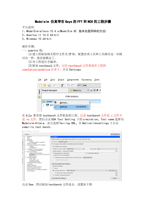
(3)贴加testbench文件,记住testbench文件要放在工程的simulation\modelsim目录下,点击Settings在file那里将testbanch文件贴加到工程,注意testbanch文件是.v文件不是.vo文件,然后点击EDA Tool Setting下的simulation,Toolname选择为Modelsim-Altera,语言选择V erilog HDL,在Nativelinksettings下点击compliletestbench,点击New,然后贴加testbench文件进去,设置如下图然后点击ok,再对工程进行编译(也可不进行编译直接点Tool->run simulation tool->RTL simulation)。
到此quartus端的工作完毕;二、modelsim端:(1)在modelsim中建立Altera的IP仿真库。
打开modelsim,File -> Change Directory…,将工作目录更改到ModelSim的安装目录下。
然后点击File -> New -> Library…,选择a new library,建立名称为altera_13_1_lib(这个名称可以自己定)的仿真资源库。
如图174-4所示。
Compile -> Compile…,Library选择刚刚建立的altera_13_1_lib的仿真资源库,查找的范围在Quartus II的安装目录下quartus -> eda -> sim_lib 中,里面有.v和.vhd两种,分别是IP核的Verilog和VHDL仿真文件,如果只使用Verilog语句,则仅选择.v的文件即可。
LabVIEW Real-Time 模块 2014 版发行和升级说明说明书

发行和升级说明LabVIEW Real-Time 模块2014版本文档介绍LabVIEW Real-Time 模块2014版的系统要求、安装须知、新功能概述以及升级和兼容性问题。
请参考LabVIEW Real-Time 模块入门指南,其中的练习有助于您熟悉Real-Time 模块。
提示关于使用LabVIEW Real-Time 模块设计、开发和部署应用程序的编程建议,请参考LabVIEW 帮助中的Real-Time 模块最佳实践章节。
在LabVIEW 帮助的目录选项卡中选择Real-Time 模块»Real-Time 模块最佳实践查看相关内容。
目录系统要求............................................................................................................................2安装LabVIEW 2014 Real-Time 模块 (2)安装日语和简体中文语言包......................................................................................3激活Real-Time 模块.........................................................................................................3配置Real-Time 终端.........................................................................................................3新增功能. (4)RT 终端上的嵌入式用户界面....................................................................................4Real-Time Trace Viewer............................................................................................4使用Modbus VI 建立Modbus 通信.........................................................................4基于USB 的以太网...................................................................................................4USB 3.0支持.............................................................................................................4NI Linux Real-Time 终端上的英特尔® 凌动™双核处理器支持.............................4Phar Lap ETS 终端上的12核CPU 支持..................................................................5升级和兼容性问题.............................................................................................................5Real-Time 模块的已知问题..............................................................................................5参考资料. (5)相关文档和范例.........................................................................................................5NI 网站.......................................................................................................................5支持. (6)™2| |LabVIEW Real-Time 模块发行和升级说明系统要求除了需要满足LabVIEW 自述文件中列出的LabVIEW 系统要求外,LabVIEW 2014 Real-Time 模块还需要满足下列要求:•LabVIEW 2014完整版或专业版开发系统(32位)。
西门子技术问题总汇

文档标题
如何设置模拟量输入模板 SM 431-7KF00的温度补偿? 如何解决 SIMATIC BATCH 的 IL43基本设备上 hotfix 安装的问题? 如果通过 PCS7 V6.1 SP1 DVD 单独安装 SIMATIC BATCH Report 需要注意哪些设置? 为什么冗余模拟量输出模块的每个通道只有一半电流输出? 使用WinCC/Web Navigator V6.1 SP1需要什么样的操作系统和软件? 是否 COM PROFIBUS 可以使用所有版本的 GSD 文件? 如何在 WinCC flexible 中组态与S7 控制器的 Profinet 连接? 如何在操作面板上设定定时器时间, 同时如何输出定时器的剩余时间? 数据块初始值与实际值的含义 如何通过窗口对象滚动条步进调节过程值参数? 使用 SINAUT ST7 向电子邮箱接受方发送文本信息 SMS 需要做何设置? 可以使用CPU317-2PN/DP替代在iMap中组态的CPU315-2PN/DP吗? 什么情况下插入C-PLUG卡或者C-PLUG有什么作用? 通过一台PC,可以使用哪种方式访问与IWLAN/PB link PNIO或IE/PB link PNIO连接的PROFIBUS设备? 当在SINAUT网络中使用4线变压器应该注意哪些设置? 在 SINAUT 网络中,使用MD3拨号调制解调器作为专线调制解调器时,要进行哪些设置? 如何安装 DCF77 天线, 当选择 DCF77 天线时需要注意什么? 使用SINAUT ST7向传真机发送文本信息时,需要进行哪些设置? 在 SINAUT 项目中发送短消息必须进行哪些特殊服务的设置? 如何在S7-300 PN CPU和CP343-1之间建立一个open TCP 通讯连接,以及如何进行数据交换? 如何在两个S7-300 PN CPU之间建立一个open TCP 通讯连接,以及如何进行数据交换? 哪些控制系统可以成功与SINAUT ST7一起使用? 使用“零-Modem”电缆连接 TIM 模块应该注意什么? 当用 SINAUT 诊断工具的ST1协议进行诊断时,为什么TIM的状态不能显示? TIM 3V-IE 和 TIM 3V-IE Advanced 模块在以太网上通信时使用哪个端口号? 如何对没有接入网络的S7-200CPU编程? 掉电后,LOGO!的程序会丢失吗? 从 PCS7 V6.1 起,为什么没有分配任何 hierarchy (PH) 的 测量点(变量)通过编译不能在OS中自动创建相应的变量? 在SFC中,如何实现从一个 Sequencer 跳出后回到另一个 Sequencer 的某个固定位置并继续执行? 如何实现过程变量的平均值归档? 存储文件的目标路径和备份可选路径有何作用? WinCC变量归档中如何实现采集周期小于500ms的变量归档? 为什么在 OS 上会显示如下信息“时间跳变通知-永久切换为从站模式”? 在西门子A&D产品支持网站是否可以下载关于ET200M的手册? 在S7-400上怎样安装冗余电源? UDT改变后怎样更新使用UDT产生的数据块。 为什么在FB块中使用OUT变量赋值被调用FB块的IN变量时出现错误信息34:4469? 如何查看4-mation导入-导出错误 不能正确引导8212-1QU IBM/Lenovo M52 ThinkCentre 实时趋势更新缓慢的原因 如何保存变量名字典CSV文件的格式
QnoSniff_Professional_2.0_UserGuide_SC

简体中文使用手册侠诺神捕QnoSniff专业版 2.0侠诺神捕QnoSniff 专业版 2.0目 录一、简介..........................................................................................................................................................4 二、QnoSniff 专业版系统安装与配置 (5)2.1 开始之前的准备..............................................................................................................................................5 2.2 QnoSniff 专业版安装过程中所需组件........................................................................................................5 2.3 布署连接范例拓朴..........................................................................................................................................6 2.4 开始安装. (6)三、启用QnoSniff 专业版 (19)3.1 启用QnoSniff 软件之前路由器的设定.....................................................................................................19 3.2 启用QnoSniff 专业版软件. (22)四、基本设定................................................................................................................................................29 五、系统权限管理. (34)5.1 观看权限........................................................................................................................................................34 5.2 使用者管理....................................................................................................................................................36 5.3 使用者日志. (38)六、群组使用者管理 (39)6.1 部门设定........................................................................................................................................................39 6.2 用户树状列表 (41)七、系统资源分析 (45)7.1 CPU 使用记录...............................................................................................................................................45 7.2 内存 (Memory) 使用记录........................................................................................................................50 7.3 WAN Traffic(广域网流量) 记录. (51)八、摘要摘要信信息 (52)8.1 即时服务总表................................................................................................................................................53 8.2 网页浏览........................................................................................................................................................54 8.3 电子邮件........................................................................................................................................................56 8.4 文件传输 (FTP)...........................................................................................................................................60 8.5 点对点下载 (P2P).......................................................................................................................................62 8.6 Telnet ............................................................................................................................................................64 8.7 聊天信息.. (67)九、统计信息 (70)9.1 流量统计报表................................................................................................................................................70 9.2 部门流量排名总表........................................................................................................................................73 9.3 使用者流量排名总表 (74)十、注销系统 (75)侠诺神捕QnoSniff 专业版 2.0十一十一、、卸载QnoSniff...................................................................................................................................77 附录附录::Qno 技术支持信息. (80)侠诺神捕QnoSniff 专业版 2.0产品功能说明手册使用许可协议《产品功能说明手册(以下称”手册”)使用许可协议》(以下称”协议”)是用户与侠诺科技股份有限公司(以下称”侠诺”)关于手册许可使用及相关方面的权利义务、以及免除或者限制侠诺责任的免责条款。
Polycom DMA 7000系统版本6.3.0_P1 补丁说明书

Patch NotesPolycom ® DMA™ 7000 System© 2015 Polycom, Inc. All rights reserved. POLYCOM®, the Polycom logo, and the names and marks associated with Po lycom’s products are trademarks and/or service marks of Polycom, Inc. and are registered and/or common law marks in the United States and various other countries. All other trademarks are property of their respective owners. 1Release label:6.3.0_P1 Built on version:Polycom DMA 7000 System v6.3.0 Released file(s):upgrade file for 6.1.x, 6.2.0, 6.2.1, and 6.3.0Purpose The primary focus of this patch is to resolve minor issues with WebRTC. Patch 1 for DMA 6.3.0 (i.e. 6.3.0_P1_Build_198923) contains code changes to address the following issues:❑DMA-14736 RealConnect conference not working properly if DMA template is configured with cascade for size. ❑DMA-14764 DMA Conference Templates could not be loaded when try to schedule pooled conference from XMA. ❑ DMA-14798 Random generated RealConnect chair codes may result in conference creation failure.❑ DMA-14825 DMA Supercluster/UnauthorizedPrefix: SIP Call with unauthorized prefix fail to establish when backup DMA forwards the call to the active DMA.❑DMA-14898 WebRTC/RPWS Intermittent IVR display – interrupts meeting. ❑DMA-14911 Max limit on WebRTC clients needs to 5. ❑DMA-14926 DMA SIP Peer – DNS resolution of Destination Network field on RE-INVITE (Outbound Calling). ❑DMA-14948 API –display-name property value changes after promotion. ❑DMA-14956 DMA doesn’t pass the participant name in the participant notification for Web RTC participant. ❑DMA-14971 Improper CANCEL handling with Weighted SIP Peers. ❑ DMA-15010 Collabutron redirect response code should be be 302 (temporary) instead of 301 (permanent).Prerequisites/Configuration Considerations∙ Systems may have Polycom DMA 7000 v6.1.x, v6.2.0, v6.2.1, or v6.3.0 installed∙ When upgrading from DMA 6.1.x, 6.2.0, 6.2.1, 6.3.0 to 6.3.0.1, the system will not preserve the call history information. To keep this data, backup the databases, upgrade the DMAs, and then restore the databases.© 2015 Polycom, Inc. All rights reserved. POLYCOM®, the Polycom l ogo, and the names and marks associated with Polycom’s products are trademarks and/or service marks of Polycom, Inc. and are registered and/or common law marks in the United States and various other countries. All other trademarks are property of their respective owners.2 NOTE : Upgrades from DMA 6.2.2.x to 6.3.0.1 are not supported5.0.x5.1.x→ → 5.2.x Yes DMA-upgrade_5.2.2.6-bld9r144761.bin 5.2.x6.0.x→ → 6.1.x n/a rppufconv.bin (Pre 6.1.0 to 6.1.3.1) 6.1.3_P1_Build_185272-rppufconv.bin 6.1.x6.2.0.x6.2.1.x → → → 6.3.0.1 Yes full.bin (Upgrade to 6.3.0.1) 6.3.0_P1_Build_198923-full.bin 6.3.0 → 6.3.0.1 No full.bin (Upgrade to 6.3.0.1)6.3.0_P1_Build_198923-full.bin6.2.2X 6.3.0.1 Not supported 6.2.2.x X 6.3.0.1 Not supportedInstallation Notes1. Download the upgrade file for dma_6.3.0.12. Login to DMA and navigate to Maintenance > Software Upgrade3. Select “Upload and Upgrade ” and choose the upgrade file4. DMA processes and applies patch。
- 1、下载文档前请自行甄别文档内容的完整性,平台不提供额外的编辑、内容补充、找答案等附加服务。
- 2、"仅部分预览"的文档,不可在线预览部分如存在完整性等问题,可反馈申请退款(可完整预览的文档不适用该条件!)。
- 3、如文档侵犯您的权益,请联系客服反馈,我们会尽快为您处理(人工客服工作时间:9:00-18:30)。
处理器IP
请看下一张幻灯片
提供100多个Qsys兼容IP,以后会提供更多。
© 2011 Altera Corporation—Public
10
多种嵌入式处理器
SoC FPGA
SOFT PROCESSOR
Cortex A9
面向非ALTERA器件的处理器
ASIC
FPGA Design Software
移植演示
较低的转换成本
移植AN632
© 2011 Altera Corporation—Public
24
在您开始试验之前
笔记本计算机密码: T60 用户:student 密码:QuartusII.1 安装试验文件
1. 双击C:\Qsys_Workshop_Lab_files.exe 2. 解压至文件夹:C:\<path>\Qsys_workshop 您可以使用您的姓名作为路径(C:\jsmith\Qsys_workshop) 在路径名称中不要使用空白 3. 点击Unzip T510 用户名:28nmworkshop 密码:Mktg.123
分层支持系统重用
系统 C
Qsys系统
系统 A
完成 Qsys系统 作为 子系统 重新使用
系统 B
Qsys子系统
Qsys 子系统
通过重新使用子系统来加速开发
© 2011 Altera Corporation—Public
19
通过分层提高灵活性
SOPC Builder
Qsys 子系统
分层设计
子系统设计更灵活 显示更少的组件 = 更容易管理(更快的GUI)
© 2011 Altera Corporation—Public
20
3.验证难题
提取/探测100/1000寄存器需要花费大量的时间 Qsys通过读写操作加速了验证过程
对地址位置进行读写操作而不是对每个寄存器进行读写操作
系统控制器
FPGA
A
Bridge IP
JTAG
View Data in Real-Time
12
芯片网络体系结构
会话层
将会话转换为数据包,将 数据包转换为会话。
传送层
将数据包传送至目的地
会话层
将会话转换为数据包,将 数据包转换为会话。
Avalon-MM
Avalon-ST
Avalon-MM
主机接口
主机网络 接口
Avalon ST 网络 (命令)
从机网络 接口
从机接口
主机接口
主机网络 接口
FPGA设计难题
Maximum Density for Stratix Series FPGAs
1200
1.
您的设计团队规模是不是越来越大?
设计规模增大 ≠ 设计团队规模增大
Logic Density (K)
900
Grew >13X
2.
600
您是否花费很多时间来尝试重新使用其 他人的设计?
设计重用 = 设计支持
Qsys:自动集成任务
自动完成繁琐、容易出错的集成任务
GUI界面支持 快速集成
接口协议 存储器
DSP
嵌入式 桥接
PLL
IP 1 Custom 1 IP 2 IP 3 Custom 2
处理器
加速开发
避免了繁琐而又容易出错的集成任务
HDL
自动完成容易出错的集成任务
© 2011 Altera Corporation—Public
标准接口
经过的维护以及可用的文档 例如:Altera的Avalon接口、ARM的
AMBA AXI接口 您不需要重新设计接口
Avalon是一个开放标准接口
© 2011 Altera Corporation—Public
16
业界标准接口
Qsys支持不同接口的混合
Example System
面向ALTERA器件的处理器
System Integration Tool
Cortex-M1
DesignWare IP SYNOPSYS SLS ARROW H-CELL SC DO-254
ColdFire V1
IPEXTREME
…一个FPGA设计流程覆盖各类嵌入式处理器
© 2011 Altera Corporation—Public
7
Qsys:Altera的系统集成工具
高性能互联
分层
基于芯片网络(NoC)体系结构
设计重用
封装为IP 设计系统 增加到 库中
业界标准接口
Avalon® 接口
®
实时系统调试
AMBA® AXI
让Qsys在您需要的地方提高您的效能
© 2011 Altera Corporation—Public
8
1.越来越大的设计规模难题
fMAX (MHz)
131 161 (+23%) 225 (+71%) 243 (+85%) 254 (+93%) 314 (+138%)
使用的资源(ALMs)
12766 13999 (+10%) 11260 (-12%) 12761 (+0%) 14206 (+11%) 26782(+110%)
Qsys将性能提高了近2倍
其他用户:在Qsys中设计整个系统
编译设计,对评估板进行编程,观察LED计数。 采用系统控制台来控制设计,进行调试
© 2011 Altera Corporation—Public
简单的分层Qsys系统
led_system.qsys nios_subsystem.qsys
data & interrupt
Master Avalon 1 Master Avalon 2 Master 3
P A C K E T
P A C K E T
Avalon Avalon AXI
Slave 1 Slave 2 Slave 3
P A C K E T
P A C K E T
AXI
P A C K E T
Qsys互联
P A C K E T
300
0
Stratix FPGAs (2002) Stratix II Stratix III Stratix IV Stratix V FPGAs FPGAs FPGAs FPGAs (2004) (2006) (2008) (2010)
3.
您是否花费大量的时间来进行验证?
在有限的资源下,很难按计划完成设计验证。
© 2011 Altera Corporation—Public
15
2.设计重用难题
设计重用一般会导致:
设计者需重新设计接口 设计者需对各种修改过的设计提供支持 没有文档(其他人不得不搞明白接口是怎样工
重用的设计
作的)
设计功能 (算法)
设计接口 (每个工程都 会改变)
Qsys增强了设计重用:
将评估板连接至您的笔记本计算机USB端口
您应该看到LED工作Fra bibliotek© 2011 Altera Corporation—Public
25
Qsys嵌入式设计试验
© 2011 Altera Corporation—Public
试验目标
采用分层功能建立一个Qsys系统 SOPC Builder用户:从SOPC Builder移植部分设计
B
C
D
master_write_16 PCIe 0x00 16 master_write_16 A 0x00 16 master_write_16 B 0x00 16 read_write_16 PCIe 0x00 read_write_16 A 0x00 read_write_16 B 0x00
采用实时系统调试方案加快电路板开发
UART
Nios II Console
clock
reset Nios® II Processor
data
Pipeline Bridge
Parallel I/O (led_pio) JTAG to Avalon Master Bridge
多种即插即用知识产权(IP):
接口协议IP 例如,PCIe, TSE
存储器IP 例如,DDR/DDR2/DDR3 视频和图像处理(VIP) IP 例如,VIP套装包括,缩放器、矩阵、去隔 行器以及alpha混合合成器。 嵌入式IP 例如,JTAG, UART, SPI, RS232
Avalon ST 网络 (响应)
从机网络 接口
从机接口
© 2011 Altera Corporation—Public
13
自动集成实例:时序收敛
Qsys支持快速设计更改
例如,不需要编写HDL就可以提高性能
外设
外设
Qsys互联(基于NoC体系结构)
外设
med low off high
外设
短时间内就可以完成时序收敛
3
有机会赢得一块Cyclone IV FPGA评估板
DE0-nano
由Terasic开发 由Arrow、Farnell、Digikey, & Terasic提供
© 2011 Altera Corporation—Public
4
采用Qsys实现系统集成
© 2011 Altera Corporation—Public
议程
采用Qsys提高设计效能 Qsys嵌入式设计试验 休息 采用Qsys轻松开发PCIe设计 Qsys 结束