L1050_SPEC_V1.1
立创片式铝电解电容器规格书说明书
公司地址:广东省东莞市长安镇沙头裕成路1号承兴电子高新技术科技园81604911、81604922版 本version日 期Date A-02022/6/21第一次发行卢英桃变更申请记录/Change Request Record变更内容 Change The Content制 作ProducerPart Number System(产品编码)12345679101112131415182021TOL.CodeLG LR 104J B P0ER PR 224K C PH MV 334L D VT VD 474M E SM SX 105N F KS KF 225G GM KM 335I GS EF 475K ZF GR 106L LF GF 226N EL AL 336O KL HL 476P FL GL 107Q ML ZL 227R PL RL 337S LM LK 687T LH LL 158U NM NS 229X NP NH 339CodeBP PZ 479G6MZ FZ 10T 5D LZ PF 15T 5E AP PE 22T 5T LS LP 33T 6B FP PN 10M 7G MN MG 22M 9MBPG187A512C5D5E5F516G51720212530354045458161719COLORSHAPERROBlack SERIESCAPCITANCEVOLTAGECASE SIZETYPESLEEVEOTHERSCase Size Liameten BackgroundCode Special 0.1±5%40043 Bulk 0.22±10% 6.36R34PCB Termial 80085Ammo Taping H No special Green L Violet Other trademark Navy blue 0.47±20%10010 6.3 2.0mm Pitch 2.5mm Pitch T250.33±15% 3.5mm Pitch T20Light purple 1±30%160168Sky blue 3.303503512.5 5.0mm Pitch T50Coffee 2.2-20%5005016Lead Cut & FormT35-40%2502510Orange red 1006306318C-Type CXX Transparentblue 4.7V-Type VXX 22-20%8008022E-Type 12012030Q-Type EXX 3310%10010025QXX 10040%16016035P-Type PXX 47-20%Printing color 220-10%20020040W-Type WXX Black 1HXX 33020%22022051K-Type GoldenKXX White 2680025025063.5H-Type 150020%31531576Y-Type22000035035090I 3300050%400400Len.(mm)47000-5+204204206100000450450 5.4150000500500 5.5220000550550 5.8PET S E Plane F 3300006006006.2PVC9V-chipConvex T 10000007.7Snap-in V18010.522000001212.513.514.515.51616.517202125303540Code Code W AC X V R Code WO X0G0VXCXSeries Cap(MFD)Tolerance VoltageCode Feature Code Z Ø8 F=2.5mm Finite height KSpecial voltageMSpecial capacitanceS T Transparent yellowYSleeve MaterialCode Rubber Shape Code 4Silvery 3YXX V-CHIPNB116.17.18 CODE Polymer NB2V序号No 目录INDEX页page1 概述SCOPE 32 外形尺寸图及尺寸表Case size table 33 技术性能 SPECIFICATIONS 44 称电容量、额定电压、额定纹波电流与外形尺寸对应表Nominal capacitance, rated voltage, rated ripple current and casesize table5-65 构造图及材料表 Frame drawing and materials 76 试验方法及要求 TESTS8-117 标志 Marking 128 片式铝电解电容的编带V- Chip Type Aluminum Electrolytic Capacitors13一、概述 SCOPE本产品规格书适用于东莞承兴电子科技有限公司VT型片式铝电解电容器产品。
深圳市海凌科电子有限公司 HLK-N10 产品 NV 配置说明说明书

深圳市海凌科电子有限公司HLK-N10产品NV配置说明版本:V1.0修订日期:2020年7月28日版权所有©深圳市海凌科电子有限公司目录1文档概述 (1)2协议栈NV参数 (1)3平台NV参数 (2)4RF相关NV参数 (4)版本历史 (5)1文档概述本文档主要用于指导用户在使用海凌科HLK-N10产品过程中对NV参数修改配置进行说明和介绍,文档详细介绍了协议栈、平台及射频相关的NV参数释义和使用说明,方便用户进行配置参考。
2协议栈NV参数变量名DEBUG值推荐值含义说明OosTimerLen60s不建议修改丢失覆盖后,周期性搜网的间隔0~65535,单位:stNvData.tNasNv.ucUpReqFlg0不建议修改设置终端是否优先走UP模式0:不优先走up1:优先走uptNvData.tNasNv.ucNoSimS lpTimeLen 默认127不建议修改设置无卡情况下进入深睡眠的延迟时长127:无限长1~126:具体时长单位:stNvData.tNasNv.ucAutoConnectFlg1不建议修改设置终端在上电/重启后是否主动尝试连接到网络0:不主动连接1:主动连接tNvData.tNasNv.ucSuppBandNum3不建议修改设置需要支持的BAND 设置的BAND需要在UE能力范围内,否则设置不生效tNvData.tNasNv.aucSuppo rtBandList[14]3,5,8 tNvData.tNasNv.ucEdrxEn ableFlg默认开不建议修改设置eDRX开关及对应的周期、PTW窗长tNvData.tNasNv.ucReqEdr xValuetNvData.tNasNv.ucPTWVal uetNvData.tNasNv.ucPsmEn ableFlg默认开不建议修改设置PSM开关及对应的周期、激活定时器时长tNvData.tNasNv.ucReqPeriodiTauValuetNvData.tNasNv.ucReqActTimeValuetNvData.tNasNv.ucERegMode默认0不建议修改参考modem AT文档参考modem AT文档3平台NV 参数用户通过以下两条AT 指令进行平台NV 的设置和读取。
华硕液晶显示器系列类型
华硕液晶显示器布局图
P 系列
PG221 LF221 PW191 LS201 LS221 MK241H MK221H MW221C VK222 VK261 VK221 VK241 VW192x+ VW198 VB191 VW222 VW202xR VW223 VW221 VW220 VW241 VW261
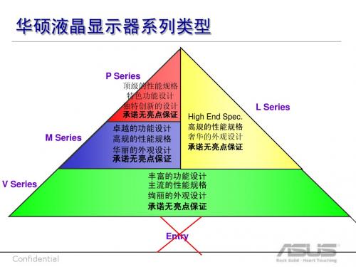
华硕液晶显示器系列类型
P Series
顶级的性能规格 特色功能设计 独特创新的设计 承诺无亮点保证
L Series
High End Spec. 高规的性能规格 奢华的外观设计 承诺无亮点保证
M Series
卓越的功能设计 高规的性能规格 华丽的外观设计 承诺无亮点保证
V Series
丰富的功能设计 主流的性能规格 绚丽的外观设计 承诺无亮点保证
Confidential
LS201特点 LS201特点
LS201 有多薄? 有多薄?
书包
杯子
可乐
书
LS201
厚度指数
Confidential
LS201晶薄系列 LS201晶薄系列
20” 1400*1050 SXGA 9H硬度的面板防护玻璃 亮度:300流明 对比度: 2000:1 (华硕动态对比技术) 16.7M色彩数 170˚(H)/160˚(V)广视角 响应时间: 5ms D-Sub / DVI双模式视频输入 一年无亮点保证 VESA 100mm( 内置变压器)
2007 07’H1 08’H1
L 系列
08’H2
M 系列
VK192 VK191
V 系列
VW161 VW171 VB171
VW192C VB172 VW192xR VW195 VW193
NXP IMXRT1050 EVKB开发板硬件用户指南说明书
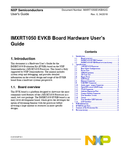
© 2018 NXP B.V.IMXRT1050 EVKB Board Hardware User’sGuide1. IntroductionThis document is a Hardware User’s Guide for theIMXRT1050 Evaluation Kit (EVKB) based on the NXP Semiconductor i.MX RT1050 Processor. This board is fully supported by NXP Semiconductor. The manual includes system setup and debugging, and provides detailedinformation on the overall design and usage of the EVKB board from a hardware systems perspective.1.1. Board overviewThis EVK board is a platform designed to showcase the most commonly used features of the i.MX RT1050 Processor in a small, low cost package. The IMXRT1050 EVKB board is an entry level development board, which gives the developer the option of becoming familiar with the processor before investing a large amount or resources in more specific designs.NXP Semiconductors Document Number: IMXRT1050EVKBHUGUser's GuideRev. 0 , 04/2018Contents1.Introduction ........................................................................ 1 1.1. Board overview ....................................................... 1 1.2. IMXRT1050 EVKB Contents ................................. 3 1.3. IMXRT1050 EVKB Board revision history............ 3 2.Specifications ..................................................................... 3 2.1. i.MX RT1050 Processor ......................................... 5 2.2. Boot Mode Configurations ...................................... 5 2.3. Power Tree .............................................................. 6 2.4. SDRAM memory .................................................... 8 2.5. SD Card Slot ........................................................... 8 2.6. Hyper Flash ............................................................. 8 2.7. QSPI Flash .............................................................. 8 2.8. Ethernet Connector ................................................. 9 2.9. USB PHY Connector .............................................. 9 2.10. Audio input / output Connector ............................... 9 2.11. OpenSDA circuit (DAP-Link) ................................ 9 2.12. JTAG Connector ................................................... 10 2.13. Arduino Expansion Port ........................................ 10 2.14. Camera Module Connector ................................... 11 2.15. User Interface Switch ............................................ 11 2.16. Sensor ................................................................... 12 2.17. User Interface LED Indicator ................................ 12 2.18. LCD Interface ....................................................... 13 3.PCB Information .............................................................. 13 4. EVKB Design Files .......................................................... 13 5. Contents of the Evaluation Kit ......................................... 14 6.Revision history (14)IntroductionFeatures of the IMXRT1050 EVKB board are shown in Table 1Specifications 1.2. IMXRT1050 EVKB ContentsThe IMXRT1050 EVKB contains the following items:•IMXRT1050 EVKB Board•USB Cable (Micro B)1.3. IMXRT1050 EVKB Board revision history•EVKB: Mass Product.NOTEEVKB Boards are based on A1 silicon.2. SpecificationsThis chapter provides detailed information about the electrical design and practical considerations of the EVKB Board, and is organized to discuss each block in the Figure 1 of the EVKB board.Figure 1. Block diagramThe overview of the IMXRT1050 EVKB Board is shown in Figure 1 & Figure 2.SpecificationsFigure 2. Overview of the IMXRT1050 EVKB Board (Front side)Figure 3. Overview of the IMXRT1050 EVKB Board (Back side)Specifications 2.1. i.MX RT1050 ProcessorThe i.MX RT1050 is a new processor family featuring NXP's advanced implementation of the ARM Cortex-M7 Core. It provides high CPU performance and best real-time response. The i.MX RT1050 provides various memory interfaces, including SDRAM, Raw NAND FLASH, NOR FLASH,SD/eMMC, Quad SPI, HyperBus and a wide range of other interfaces for connecting peripherals, such as WLAN, Bluetooth™, GPS, displays, and camera sensors. Same as other i.MX processors, i.MXRT1050 also has rich audio and video features, including LCD display, basic 2D graphics, camera interface, SPDIF and I2S audio interface.The i.MX RT1050 applications processor can be used in areas such as industrial HMI, IoT, motor control and home appliances. The architecture's flexibility enables it to be used in a wide variety of other general embedded applications too. The i.MX processor provides all interfaces necessary to connect peripherals such as WLAN, Blueto oth™, GPS, camera sensors, and multiple displays.The more detail information about i.MX RT1050 can be found in the Datasheet and Reference manual.2.2. Boot Mode ConfigurationsThe device has four boot modes (one is reserved for NXP use). The boot mode is selected based on the binary value stored in the internal BOOT_MODE register. Switch (SW7-3 & SW7-4) is used to select the boot mode on the IMXRT1050 EVKB Board.Typically, the internal boot is selected for normal boot, which is configured by external BOOT_CFG GPIOs. The following Table 3 shows the typical Boot Mode and Boot Device settings.NOTEFor more information about boot mode configuration, see the System Boot chapter of theMIMXRT1050 Reference Manual.SpecificationsFor more information about IMXRT1050 EVKB boot device selection and configuration, see the main board schematic.2.3. Power TreeA DC 5V external power supply is used to supply the IMXRT1050 EVKB Board at J2, and a slide switch SW1 is used to turn the Power ON/OFF. J28 and J9 also can be used to supply the EVKB Board. Different power supply need to configure different Jumper setting of J1. Table 4 shows the details:NOTEFor some computers’ USB, it cannot support 500 ma before establishingcommunication. In this case, it is recommended to replace the computer oruse the power adapter(J2) to power the EVKB Board.The power tree is shown in the following figure.Figure 4. Power TreeSpecificationsThe power control logic of the IMXRT1050 EVKB board is shown in Figure 5:•It will power up SNVS firstly, then PMIC_REQ_ON will be switched on to enable external DC/DC to power up other power domains.•ON/OFF button is used to switch ON/OFF PMIC_REQ_ON to control power modes.•RESET button and WDOG output are used to reset the system power.Figure 5. Power Control DiagramThe power rails on the board are shown in Table 5.Specifications1 For silicon A0, DCDC_IN voltage domain is 2.9V~3.1V2.4. SDRAM memoryOne 256 Mb, 166 MHz SDRAM (MT48LC16M16A2B4-6AIT: G) is used on the EVK Board.2.5. SD Card SlotThere is a SD card slot(J20) on the IMXRT1050 EVKB Board.J20 is the Micro SD slot for USDHC1 interface. If the developer wants to boot from the SD Card, the boot device switch (SW7) settings should be: ON, OFF, ON, OFF, as shown in Table 3.2.6. Hyper FlashOn the IMXRT1050 EVKB Board, there is one 512 Mbit Hyper Flash device. If the developer wants to boot from the Hyper Flash, the boot device switch (SW7) settings should be: OFF. ON, ON, OFF, as shown in Table 3.2.7. QSPI FlashA 64Mbit QSPI Flash is used on the IMXRT1050 EVKB Board. If the developer wants to boot from the QSPI Flash, the boot device switch(SW7) settings should be: OFF, OFF, ON, OFF, as shown in Table 3. By default, this QSPI Flash is disabled on the EVKB. To enable the onboard QSPI Flash, the settings need to be changed.Specifications Step1:Removed resistors: R356, R361 - R366.Step2:Weld 0Ωresistors: R153 - R158.2.8. Ethernet ConnectorThere is one Ethernet Mac controller in the MIMXRT1050 processor. The Ethernet subsystem of the IMXRT1050 EVKB Board is provided by the KSZ8081RNB 10/100M Ethernet Transceiver (U16) anda RJ45 (J19) with integrated Magnetic.2.9. USB PHY ConnectorThe MIMXRT1050 contains 2 integrated USB 2.0 PHYs capable of connecting to USB host/device systems at the USB low-speed (LS) rate of 1.5 Mbits/s, full-speed (FS) rate of 12 Mbits/s or at the USB 2.0 high-speed (HS) rate of 480 Mbits/s.2.10. Audio input / output ConnectorThe Audio CODEC used on the IMXRT1050 EVKB Board is Wolfson’s Low Power, high quality Stereo Codec, WM8960.The IMXRT1050 EVKB Board include one headphone interface (J12), one onboard MIC (P1), two speaker interfaces (J16, J17), and the SPDIF interface (J14 & J18, DNP). J12 isa 3.5mm audio stereo headphone jack, which supports jack detect.2.11. OpenSDA circuit (DAP-Link)The OpenSDA circuit (CMSIS–DAP) is an open-standard serial and debug adapter. It bridges serial and debug communications between a USB host and an embedded target processor.CMSIS-DAP features a mass storage device (MSD) bootloader, which provides a quick and easy mechanism for loading different CMSIS-DAP Applications such as flash programmers, run-control debug interfaces, serial-to-USB converters, and more. Two or more CMSIS-DAP applications can run simultaneously. For example, run-control debug application and serial-to-USB converter runs in parallel to provide a virtual COM communication interface while allowing code debugging via CMSIS-DAP with just single USB connection.For the IMXRT1050 EVKB Board, J28 is the connector between the USB host and the target processor. Jumper to serial downloader mode to use stable DAP-Link debugger function. If developer wants to make OpenSDA going to the bootloader mode, J27 should jumper to 1-2, and press SW4 when power on. Meanwhile, the OpenSDA supports drag/drop feature for U-Disk. First, use the seral downloader mode and drag/drop the image file to U-Disk. Then select Hyper Flash as boot device and reset the Board, the image will run.Specifications2.12. JTAG ConnectorJ21 is a standard 20-pin/2.54 mm Box Header Connector for JTAG. The pin definitions are shown in the Figure 6. Support SWD by default.Figure 6. JTAG pin definitions2.13. Arduino Expansion PortJ22 – J25 is defined as Arduino Interface. The pin definitions of Arduino Interface are shown in Table 6.SpecificationsNOTEJ24 PIN9&PIN10 are not compatible with ARDUINO I2C, please use orwire to J23 PIN5&PIN6 instead and it will correct in next revision.2.14. Camera Module ConnectorOne parallel CSI (Camera Sensor Interface) is supported by the i.MX RT1050. There is a Camera Module Connector (J35) on the IMXRT1050 EVKB Board. The CA031C based on OV7725 andCA111C based on MT9M114 can be used directly.NOTEJ35 supports both MT9M114 and OV7725 camera module, but 3.3V is aviolation to MT9M114 spec 3.1V. It proved fine for evaluation/demo with3.3V supply, but in product design, it is recommended to adjust DCDCoutput or add level shifter.2.15. User Interface SwitchThere are four user interface switches on the IMXRT1050 EVKB Board. Their functionality is as below.Specifications2.15.1. Power SwitchSW1 is a slide switch to control the power of the IMXRT1050 EVKB Board when the power supply is from J2. The function of this switch is listed below:•Sliding the switch to the ON position connects the 5 V power supply to the Evaluation board main power system.•Sliding the switch to OFF position immediately removes all power from the board.2.15.2. ON/OFF ButtonSW2 is the ON/OFF button for IMXRT1050 EVKB Board. A short pressing in OFF mode causes the internal power management state machine to change state to ON. In ON mode, a short pressing generates an interrupt (intended to be a software-controllable(power-down). An approximate 5 seconds or more pressing causes a forced OFF. Both boot mode inputs can be disconnected.2.15.3. Reset ButtonThere are two Reset Button on the EVK Board. SW3 is the Power On Reset Button. Pressing the SW3 in the Power On state will force to reset the system power except SNVS domain. The Processor will be immediately turn off and reinitiate a boot cycle from the Processor Power Off state. SW4 is Reset Button.2.15.4. USER ButtonSW8 is the USER Button(GPIO5-00) for developers using. Pressing can produce changes in high and low levels.2.16. SensorU32 on the EVK Board is a 6-Axis Ecompass (3-Axis Mag, 3-Axis Accel) sensor FXOS8700CQ. The Ecompass is connected to i.MX RT1050 I2C1 port.2.17. User Interface LED IndicatorThere are four LED status indicators located on the EVK Board. The functions of these LEDs include: •Main Power Supply(D3)Green: DC 5V main supply is normal.Red: J2 input voltage is over 5.6V.Off: the board is not powered.•Reset RED LED(D15)•OpenSDA LED(D16)•USER LED(D18)EVKB Design Files 2.18. LCD InterfaceThe enhanced Liquid Crystal Display Interface (eLCDIF) is a general purpose display controller.The eLCDIF block supports the following:•Displays that support moving pictures and require the RGB interface mode (DOTCLK interface). The eLCDIF provides fully programmable functionality to supported interfaces:•Bus master interface to source frame buffer data for display refresh.•8/16/18/24/32 bit LCD data bus support available depending on I/O mux options.•Programmable timing and parameters for DOTCLK LCD interfaces.If developers want to use LCD, NXP provides an optional LCD module RK043FN02H-CT which has a 4.3 inches touch-screen and supports a resolution of up to 480*3(RGB)*272. This module contains two FPC cables. The LCD interface can be connected to J8(A1-A40) and the CPT interface can be connected to J8(B1-B6). LCD modules can be purchased from the NXP website.3. PCB InformationThe IMXRT1050 EVKB Board is made using standard 4-layer technology. The material used was FR-4. The PCB stack-up information is shown in Table 7.4. EVKB Design FilesThe schematics, layout files, and gerber files (including Silkscreen) can be downloaded from/MIMXRT1050-EVKRevision history5. Contents of the Evaluation KitNOTEPower adaptor, Micro SD Card, LCD Module and Camera Module are not standard parts of the Evaluation Kit.6. Revision historyTable 9 summarizes the changes made to this document since the initial release.Document Number: IMXRT1050EVKBHUGRev. 0 04/2018How to Reach Us: Home Page: Web Support: /supportInformation in this document is provided solely to enable system and softwareimplementers to use NXP products. There are no express or implied copyright licenses granted hereunder to design or fabricate any integrated circuits based on the information in this document. NXP reserves the right to make changes without further notice to any products herein.NXP makes no warranty, representation, or guarantee regarding the suitability of its products for any particular purpose, nor does NXP assume any liability arising out of the application or use of any product or circuit, and specifically disclaims any and all liability, including without limitation consequenti al or incidental damages. “Typical” parameters that may be provided in NXP data sheets and/or specifications can and do vary in different applications, and actual performance may vary over time. All operating parameters, including “typicals,” must be valid ated for each customer application by customer’s technical experts. NXP does not convey any license under its patent rights nor the rights of others. NXP sells products pursuant to standard terms and conditions of sale, which can be found at the following address: /SalesTermsandConditions . NXP, the NXP logo, NXP SECURE CONNECTIONS FOR A SMARTER WORLD, Freescale, the Freescale logo are the trademarks of NXP B.V. All other product or service names are the property of their respective owners.Arm, the Arm logo, and Cortex are registered trademarks of Arm Limited (or its subsidiaries) in the EU and/or elsewhere.. All rights reserved. © 2018 NXP B.V.。
凌阳方案升级工具

W35: 没有 tts 文件!
S1:状态: 连接
S2:状态: 未连接
S3:状态: 格式化中,请等待...
S4:状态: 成功, 请关闭并移除设备
S5:状态: 传送 %s ...
S6:状态: 备份 %s ...
S7:状态: 校验...
E63: 获取 CIS USB Block 失败!!
E64: 写 CIS(%x) page%x失败!!
E65: 无法获取机器容量大小!! 无法得知总扇区数!!
E66: 读回 MBR 资料错误!! Rd[%x]=%x != Wr[%x]=%x
E67: 写 MBR 及 隐藏扇区 失败!!
E68: 读回PBR (sector %x) 资料错误!! Rd[%x]=%x != Wr[%x]=%x
E34: 构建备份 CIS 失败!
E35: 格式化后, 复制备份 CIS 到 CIS 失败!
E36: 填入 Spare SRAM %d 失败!
E37: 读 ID 失败!
E38: 读 spare %d 失败!
E39: 读RAM %d 失败!
E40: 写 spare %d 出错!
E41: 写 XRAM %d 出错!
E24: BankLookUpTable 错误! 写块表到 CIS: 地址 %x
E25: 块表错误! 读CIS: 扇区 %x RData[%x]=%x Table[%x]=%x
E26: 不匹配! CIS 块地址: 0x%x-0x%x, Kernel 块地址: 0x%x-0x%x, 第1个好块:0x%x
U36:点击"完成"按钮来关闭此工具
hcs12 mc9s12zvm-family 參考手冊说明书

MC9S12ZVM-Family Reference Manual HCS12MicrocontrollersTo provide the most up-to-date information, the document revision on the Internet is the most current. A printed copy may be an earlier revision. To verify you have the latest information available, refer to :.This document contains information for all constituent modules, with the exception of the S12Z CPU. For S12ZCPU information please refer to the CPU S12Z Reference Manual.S12ZVM32 and S12ZVM16 specific information is preliminary until these devices are qualified.The following revision history table summarizes changes contained in this document. The individual module sections contain revision history tables with more detailed information.Freescale Semiconductor reserves the right to make changes without further notice to any products herein. Freescale Semiconductor makes no warranty,representation or guarantee regarding the suitability of its products for any particular purpose, nor does Freescale Semiconductor assume any liability arising out of the application or use of any product or circuit, and specifically disclaims any and all liability, including without limitation consequential or incidental damages. “Typical” parameters that may be provided in Freescale Semiconductor data sheets and/or specifications can and do vary in different applications and actual performance may vary over time. All operating parameters, including “Typicals”, must be validated for each customer application by customer’s technical experts. Freescale Semiconductor does not convey any license under its patent rights nor the rights of others. Freescale Semiconductor products are not designed, intended, or authorized for use as components in systems intended for surgical implant into the body, or other applications intended to support or sustain life, or for any other application in which the failure of the Freescale Semiconductor product could create a situation where personal injury or death may occur. Should Buyer purchase or Table 0-1. Revision History DateRevision Description 12 Dec 2013 1.2 Replaced generic 8-channel TIM section with specific 4-channel TIM sectionTextual enhancements and corrections throughoutUpdated electrical parameter section and added parameters for temperataures up to 175°C- Added Table A-5- Merged Table A-8 and A-9 into Table A-9. Values updated. .- Table A-15. Parameter #2. max changed from 800uA to 1050uA- Table A-15. Inserted new C class parameter ISUPS at 85C. typ. 80uA- Appendices B,D and E. Updated parameter values based on characterization results.- Appendix C. Added parameter values for range above T=150°C- Table F-3. Merged rows 2a and 2b. Merged rows 6a and 6b.- Appendix G. Merged tables G-1 and G-2.- Tables H-1 and H-2 values updated.20 JAN 2014 1.3Updated Stop mode description for BDC enabled caseRemoved false reference to modified clock monitor assert frequencyUpdated electricals for 175°C Grade0- Removed temperature range disclaimer from electrical parameter spec.footer- Added sentence above table A-3- Table D-1. LINPHY parameters 12a and 12b replaced by 12a, 12b and 12c-- Table D-2. LINPHY wake up pulse over whole temperature range- Table E-1. FET gate charge spec. updated22 MAY2014 1.4Updated family derivative table for S12ZVML32, S12ZVM32 and S12ZVM16 devicesAdded 64KB, 32KB and 16KB derivative information to flash module chapterAdded pin routing options for S12ZVM32 and S12ZVM16 devicesAdded HV Phy information for the S12ZVM32 and S12ZVM16 derivativesUpdated Part ID assignment table and ordering information for S12ZVM32 and S12ZVM16Corrected PLL VCO maximum frequency specificationChanged V LVLSA maximum from 7V to 6.9VAdded electrical parameter for HD division ratio through the phase multiplexerCorrected preferred VRL reference from VRL_1 to VRL_0Included NVM timing parameters for the S12ZVM32 and S12ZVM16 devicesAdded GDU S12ZVM32 and S12ZVM16 specific differences and electrical specificationsAdded references to f WSTAT Added VDDX short circuit fall back current and temperature/input dependency specs.Chapter1Device Overview MC9S12ZVM-Family1.1Introduction . . . . . . . . . . . . . . . . . . . . . . . . . . . . . . . . . . . . . . . . . . . . . . . . . . . . . . . . . . . . . . . . . . 17 1.2Features . . . . . . . . . . . . . . . . . . . . . . . . . . . . . . . . . . . . . . . . . . . . . . . . . . . . . . . . . . . . . . . . . . . . . 181.2.1MC9S12ZVM-Family Member Comparison . . . . . . . . . . . . . . . . . . . . . . . . . . . . . . . . . 181.2.2Functional Differences Between N06E and 0N95G Masksets . . . . . . . . . . . . . . . . . . . . 191.2.3Functional Differences Between 1N95G and 0N95G Masksets . . . . . . . . . . . . . . . . . . . 20 1.3Chip-Level Features . . . . . . . . . . . . . . . . . . . . . . . . . . . . . . . . . . . . . . . . . . . . . . . . . . . . . . . . . . . . 20 1.4Module Features . . . . . . . . . . . . . . . . . . . . . . . . . . . . . . . . . . . . . . . . . . . . . . . . . . . . . . . . . . . . . . . 211.4.1S12Z Central Processor Unit (CPU) . . . . . . . . . . . . . . . . . . . . . . . . . . . . . . . . . . . . . . . . 211.4.2Embedded Memory . . . . . . . . . . . . . . . . . . . . . . . . . . . . . . . . . . . . . . . . . . . . . . . . . . . . . 221.4.3Clocks, Reset & Power Management Unit (CPMU) . . . . . . . . . . . . . . . . . . . . . . . . . . . . 231.4.4Main External Oscillator (XOSCLCP) . . . . . . . . . . . . . . . . . . . . . . . . . . . . . . . . . . . . . . 241.4.5Timer (TIM) . . . . . . . . . . . . . . . . . . . . . . . . . . . . . . . . . . . . . . . . . . . . . . . . . . . . . . . . . . . 241.4.6Pulse width Modulator with Fault protection (PMF) . . . . . . . . . . . . . . . . . . . . . . . . . . . . 241.4.7Programmable Trigger Unit (PTU) . . . . . . . . . . . . . . . . . . . . . . . . . . . . . . . . . . . . . . . . . 241.4.8LIN physical layer transceiver . . . . . . . . . . . . . . . . . . . . . . . . . . . . . . . . . . . . . . . . . . . . . 251.4.9Serial Communication Interface Module (SCI) . . . . . . . . . . . . . . . . . . . . . . . . . . . . . . . . 251.4.10Multi-Scalable Controller Area Network (MSCAN) . . . . . . . . . . . . . . . . . . . . . . . . . . . . 251.4.11Serial Peripheral Interface Module (SPI) . . . . . . . . . . . . . . . . . . . . . . . . . . . . . . . . . . . . . 261.4.12Analog-to-Digital Converter Module (ADC) . . . . . . . . . . . . . . . . . . . . . . . . . . . . . . . . . 261.4.13Supply V oltage Sensor (BATS) . . . . . . . . . . . . . . . . . . . . . . . . . . . . . . . . . . . . . . . . . . . . 261.4.14On-Chip V oltage Regulator system (VREG) . . . . . . . . . . . . . . . . . . . . . . . . . . . . . . . . . . 261.4.15Gate Drive Unit (GDU) . . . . . . . . . . . . . . . . . . . . . . . . . . . . . . . . . . . . . . . . . . . . . . . . . . 271.4.16Current Sense . . . . . . . . . . . . . . . . . . . . . . . . . . . . . . . . . . . . . . . . . . . . . . . . . . . . . . . . . . 271.4.17High V oltage Physical Interface (S12ZVM32, S12ZVM16) . . . . . . . . . . . . . . . . . . . . . . 27 1.5Block Diagram . . . . . . . . . . . . . . . . . . . . . . . . . . . . . . . . . . . . . . . . . . . . . . . . . . . . . . . . . . . . . . . . 28 1.6Device Memory Map . . . . . . . . . . . . . . . . . . . . . . . . . . . . . . . . . . . . . . . . . . . . . . . . . . . . . . . . . . . 291.6.1Flash Module . . . . . . . . . . . . . . . . . . . . . . . . . . . . . . . . . . . . . . . . . . . . . . . . . . . . . . . . . . 301.6.2Part ID Assignments . . . . . . . . . . . . . . . . . . . . . . . . . . . . . . . . . . . . . . . . . . . . . . . . . . . . 32 1.7Signal Description and Device Pinouts . . . . . . . . . . . . . . . . . . . . . . . . . . . . . . . . . . . . . . . . . . . . . 321.7.1Pin Assignment Overview . . . . . . . . . . . . . . . . . . . . . . . . . . . . . . . . . . . . . . . . . . . . . . . . 321.7.2Detailed External Signal Descriptions . . . . . . . . . . . . . . . . . . . . . . . . . . . . . . . . . . . . . . . 331.7.3Power Supply Pins . . . . . . . . . . . . . . . . . . . . . . . . . . . . . . . . . . . . . . . . . . . . . . . . . . . . . . 391.7.4Package and Pinouts . . . . . . . . . . . . . . . . . . . . . . . . . . . . . . . . . . . . . . . . . . . . . . . . . . . . 40 1.8Internal Signal Mapping . . . . . . . . . . . . . . . . . . . . . . . . . . . . . . . . . . . . . . . . . . . . . . . . . . . . . . . . . 461.8.1ADC Connectivity . . . . . . . . . . . . . . . . . . . . . . . . . . . . . . . . . . . . . . . . . . . . . . . . . . . . . . 471.8.2Motor Control Loop Signals . . . . . . . . . . . . . . . . . . . . . . . . . . . . . . . . . . . . . . . . . . . . . . 481.8.3Device Level PMF Connectivity . . . . . . . . . . . . . . . . . . . . . . . . . . . . . . . . . . . . . . . . . . . 481.8.4BDC Clock Source Connectivity . . . . . . . . . . . . . . . . . . . . . . . . . . . . . . . . . . . . . . . . . . . 481.8.5LINPHY Connectivity . . . . . . . . . . . . . . . . . . . . . . . . . . . . . . . . . . . . . . . . . . . . . . . . . . . 481.8.6HVPHY Connectivity . . . . . . . . . . . . . . . . . . . . . . . . . . . . . . . . . . . . . . . . . . . . . . . . . . . 481.8.7FTMRZ Connectivity . . . . . . . . . . . . . . . . . . . . . . . . . . . . . . . . . . . . . . . . . . . . . . . . . . . 491.8.8CPMU Connectivity . . . . . . . . . . . . . . . . . . . . . . . . . . . . . . . . . . . . . . . . . . . . . . . . . . . . 49 1.9Modes of Operation . . . . . . . . . . . . . . . . . . . . . . . . . . . . . . . . . . . . . . . . . . . . . . . . . . . . . . . . . . . . 491.9.1Chip Configuration Modes . . . . . . . . . . . . . . . . . . . . . . . . . . . . . . . . . . . . . . . . . . . . . . . 491.9.2Debugging Modes . . . . . . . . . . . . . . . . . . . . . . . . . . . . . . . . . . . . . . . . . . . . . . . . . . . . . . 501.9.3Low Power Modes . . . . . . . . . . . . . . . . . . . . . . . . . . . . . . . . . . . . . . . . . . . . . . . . . . . . . . 50 1.10Security . . . . . . . . . . . . . . . . . . . . . . . . . . . . . . . . . . . . . . . . . . . . . . . . . . . . . . . . . . . . . . . . . . . . . . 511.10.1Features . . . . . . . . . . . . . . . . . . . . . . . . . . . . . . . . . . . . . . . . . . . . . . . . . . . . . . . . . . . . . . 511.10.2Securing the Microcontroller . . . . . . . . . . . . . . . . . . . . . . . . . . . . . . . . . . . . . . . . . . . . . . 511.10.3Operation of the Secured Microcontroller . . . . . . . . . . . . . . . . . . . . . . . . . . . . . . . . . . . . 521.10.4Unsecuring the Microcontroller . . . . . . . . . . . . . . . . . . . . . . . . . . . . . . . . . . . . . . . . . . . . 521.10.5Reprogramming the Security Bits . . . . . . . . . . . . . . . . . . . . . . . . . . . . . . . . . . . . . . . . . . 531.10.6Complete Memory Erase . . . . . . . . . . . . . . . . . . . . . . . . . . . . . . . . . . . . . . . . . . . . . . . . . 53 1.11Resets and Interrupts . . . . . . . . . . . . . . . . . . . . . . . . . . . . . . . . . . . . . . . . . . . . . . . . . . . . . . . . . . . 541.11.1Resets . . . . . . . . . . . . . . . . . . . . . . . . . . . . . . . . . . . . . . . . . . . . . . . . . . . . . . . . . . . . . . . . 541.11.2Interrupt Vectors . . . . . . . . . . . . . . . . . . . . . . . . . . . . . . . . . . . . . . . . . . . . . . . . . . . . . . . 541.11.3Effects of Reset . . . . . . . . . . . . . . . . . . . . . . . . . . . . . . . . . . . . . . . . . . . . . . . . . . . . . . . . 57 1.12Module device level dependencies . . . . . . . . . . . . . . . . . . . . . . . . . . . . . . . . . . . . . . . . . . . . . . . . . 581.12.1CPMU COP Configuration . . . . . . . . . . . . . . . . . . . . . . . . . . . . . . . . . . . . . . . . . . . . . . . 581.12.2CPMU High Temperature Trimming . . . . . . . . . . . . . . . . . . . . . . . . . . . . . . . . . . . . . . . . 581.12.3Flash IFR Mapping . . . . . . . . . . . . . . . . . . . . . . . . . . . . . . . . . . . . . . . . . . . . . . . . . . . . . 58 1.13Application Information . . . . . . . . . . . . . . . . . . . . . . . . . . . . . . . . . . . . . . . . . . . . . . . . . . . . . . . . . 591.13.1ADC Calibration . . . . . . . . . . . . . . . . . . . . . . . . . . . . . . . . . . . . . . . . . . . . . . . . . . . . . . . 591.13.2SCI Baud Rate Detection . . . . . . . . . . . . . . . . . . . . . . . . . . . . . . . . . . . . . . . . . . . . . . . . . 591.13.3Motor Control Application Overview . . . . . . . . . . . . . . . . . . . . . . . . . . . . . . . . . . . . . . . 601.13.4BDCM Complementary Mode Operation . . . . . . . . . . . . . . . . . . . . . . . . . . . . . . . . . . . . 681.13.5BLDC Six-Step Commutation . . . . . . . . . . . . . . . . . . . . . . . . . . . . . . . . . . . . . . . . . . . . . 721.13.6PMSM Control . . . . . . . . . . . . . . . . . . . . . . . . . . . . . . . . . . . . . . . . . . . . . . . . . . . . . . . . . 741.13.7Power Domain Considerations . . . . . . . . . . . . . . . . . . . . . . . . . . . . . . . . . . . . . . . . . . . . 78Chapter2Port Integration Module (S12ZVMPIMV2)2.1Introduction . . . . . . . . . . . . . . . . . . . . . . . . . . . . . . . . . . . . . . . . . . . . . . . . . . . . . . . . . . . . . . . . . . 832.1.1Overview . . . . . . . . . . . . . . . . . . . . . . . . . . . . . . . . . . . . . . . . . . . . . . . . . . . . . . . . . . . . . 832.1.2Features . . . . . . . . . . . . . . . . . . . . . . . . . . . . . . . . . . . . . . . . . . . . . . . . . . . . . . . . . . . . . . 84 2.2External Signal Description . . . . . . . . . . . . . . . . . . . . . . . . . . . . . . . . . . . . . . . . . . . . . . . . . . . . . . 84 2.3Memory Map and Register Definition . . . . . . . . . . . . . . . . . . . . . . . . . . . . . . . . . . . . . . . . . . . . . . 882.3.1Register Map . . . . . . . . . . . . . . . . . . . . . . . . . . . . . . . . . . . . . . . . . . . . . . . . . . . . . . . . . . 892.3.2PIM Registers 0x0200-0x020F . . . . . . . . . . . . . . . . . . . . . . . . . . . . . . . . . . . . . . . . . . . . 932.3.3PIM Generic Registers . . . . . . . . . . . . . . . . . . . . . . . . . . . . . . . . . . . . . . . . . . . . . . . . . . 1012.3.4PIM Generic Register Exceptions . . . . . . . . . . . . . . . . . . . . . . . . . . . . . . . . . . . . . . . . . 109 2.4Functional Description . . . . . . . . . . . . . . . . . . . . . . . . . . . . . . . . . . . . . . . . . . . . . . . . . . . . . . . . . 1102.4.1General . . . . . . . . . . . . . . . . . . . . . . . . . . . . . . . . . . . . . . . . . . . . . . . . . . . . . . . . . . . . . . 1102.4.2Registers . . . . . . . . . . . . . . . . . . . . . . . . . . . . . . . . . . . . . . . . . . . . . . . . . . . . . . . . . . . . . 1112.4.3Pin I/O Control . . . . . . . . . . . . . . . . . . . . . . . . . . . . . . . . . . . . . . . . . . . . . . . . . . . . . . . . 1122.4.4Interrupts . . . . . . . . . . . . . . . . . . . . . . . . . . . . . . . . . . . . . . . . . . . . . . . . . . . . . . . . . . . . 1132.4.5Pin interrupts and Key-Wakeup (KWU) . . . . . . . . . . . . . . . . . . . . . . . . . . . . . . . . . . . . 1142.4.6Over-Current Interrupt . . . . . . . . . . . . . . . . . . . . . . . . . . . . . . . . . . . . . . . . . . . . . . . . . . 1152.5Initialization and Application Information . . . . . . . . . . . . . . . . . . . . . . . . . . . . . . . . . . . . . . . . . . 1152.5.1Port Data and Data Direction Register writes . . . . . . . . . . . . . . . . . . . . . . . . . . . . . . . . 1152.5.2Over-Current Protection on EVDD1 . . . . . . . . . . . . . . . . . . . . . . . . . . . . . . . . . . . . . . . 115Chapter3Memory Mapping Control (S12ZMMCV1)3.1Introduction . . . . . . . . . . . . . . . . . . . . . . . . . . . . . . . . . . . . . . . . . . . . . . . . . . . . . . . . . . . . . . . . . 1173.1.1Glossary . . . . . . . . . . . . . . . . . . . . . . . . . . . . . . . . . . . . . . . . . . . . . . . . . . . . . . . . . . . . . 1183.1.2Overview . . . . . . . . . . . . . . . . . . . . . . . . . . . . . . . . . . . . . . . . . . . . . . . . . . . . . . . . . . . . 1183.1.3Features . . . . . . . . . . . . . . . . . . . . . . . . . . . . . . . . . . . . . . . . . . . . . . . . . . . . . . . . . . . . . 1183.1.4Modes of Operation . . . . . . . . . . . . . . . . . . . . . . . . . . . . . . . . . . . . . . . . . . . . . . . . . . . . 1193.1.5Block Diagram . . . . . . . . . . . . . . . . . . . . . . . . . . . . . . . . . . . . . . . . . . . . . . . . . . . . . . . . 119 3.2External Signal Description . . . . . . . . . . . . . . . . . . . . . . . . . . . . . . . . . . . . . . . . . . . . . . . . . . . . . 119 3.3Memory Map and Register Definition . . . . . . . . . . . . . . . . . . . . . . . . . . . . . . . . . . . . . . . . . . . . . 1203.3.1Memory Map . . . . . . . . . . . . . . . . . . . . . . . . . . . . . . . . . . . . . . . . . . . . . . . . . . . . . . . . . 1203.3.2Register Descriptions . . . . . . . . . . . . . . . . . . . . . . . . . . . . . . . . . . . . . . . . . . . . . . . . . . . 120 3.4Functional Description . . . . . . . . . . . . . . . . . . . . . . . . . . . . . . . . . . . . . . . . . . . . . . . . . . . . . . . . . 1253.4.1Global Memory Map . . . . . . . . . . . . . . . . . . . . . . . . . . . . . . . . . . . . . . . . . . . . . . . . . . . 1253.4.2Illegal Accesses . . . . . . . . . . . . . . . . . . . . . . . . . . . . . . . . . . . . . . . . . . . . . . . . . . . . . . . 1273.4.3Uncorrectable ECC Faults . . . . . . . . . . . . . . . . . . . . . . . . . . . . . . . . . . . . . . . . . . . . . . . 128Chapter4Interrupt (S12ZINTV0)4.1Introduction . . . . . . . . . . . . . . . . . . . . . . . . . . . . . . . . . . . . . . . . . . . . . . . . . . . . . . . . . . . . . . . . . 1294.1.1Glossary . . . . . . . . . . . . . . . . . . . . . . . . . . . . . . . . . . . . . . . . . . . . . . . . . . . . . . . . . . . . . 1304.1.2Features . . . . . . . . . . . . . . . . . . . . . . . . . . . . . . . . . . . . . . . . . . . . . . . . . . . . . . . . . . . . . 1304.1.3Modes of Operation . . . . . . . . . . . . . . . . . . . . . . . . . . . . . . . . . . . . . . . . . . . . . . . . . . . . 1314.1.4Block Diagram . . . . . . . . . . . . . . . . . . . . . . . . . . . . . . . . . . . . . . . . . . . . . . . . . . . . . . . . 131 4.2External Signal Description . . . . . . . . . . . . . . . . . . . . . . . . . . . . . . . . . . . . . . . . . . . . . . . . . . . . . 132 4.3Memory Map and Register Definition . . . . . . . . . . . . . . . . . . . . . . . . . . . . . . . . . . . . . . . . . . . . . 1324.3.1Module Memory Map . . . . . . . . . . . . . . . . . . . . . . . . . . . . . . . . . . . . . . . . . . . . . . . . . . 1324.3.2Register Descriptions . . . . . . . . . . . . . . . . . . . . . . . . . . . . . . . . . . . . . . . . . . . . . . . . . . . 133 4.4Functional Description . . . . . . . . . . . . . . . . . . . . . . . . . . . . . . . . . . . . . . . . . . . . . . . . . . . . . . . . . 1384.4.1S12Z Exception Requests . . . . . . . . . . . . . . . . . . . . . . . . . . . . . . . . . . . . . . . . . . . . . . . 1384.4.2Interrupt Prioritization . . . . . . . . . . . . . . . . . . . . . . . . . . . . . . . . . . . . . . . . . . . . . . . . . . 1384.4.3Priority Decoder . . . . . . . . . . . . . . . . . . . . . . . . . . . . . . . . . . . . . . . . . . . . . . . . . . . . . . . 1394.4.4Reset Exception Requests . . . . . . . . . . . . . . . . . . . . . . . . . . . . . . . . . . . . . . . . . . . . . . . 1394.4.5Exception Priority . . . . . . . . . . . . . . . . . . . . . . . . . . . . . . . . . . . . . . . . . . . . . . . . . . . . . 1404.4.6Interrupt Vector Table Layout . . . . . . . . . . . . . . . . . . . . . . . . . . . . . . . . . . . . . . . . . . . . 140 4.5Initialization/Application Information . . . . . . . . . . . . . . . . . . . . . . . . . . . . . . . . . . . . . . . . . . . . . 1404.5.1Initialization . . . . . . . . . . . . . . . . . . . . . . . . . . . . . . . . . . . . . . . . . . . . . . . . . . . . . . . . . . 1404.5.2Interrupt Nesting . . . . . . . . . . . . . . . . . . . . . . . . . . . . . . . . . . . . . . . . . . . . . . . . . . . . . . 1414.5.3Wake Up from Stop or Wait Mode . . . . . . . . . . . . . . . . . . . . . . . . . . . . . . . . . . . . . . . . 142Chapter5Background Debug Controller (S12ZBDCV2)5.1Introduction . . . . . . . . . . . . . . . . . . . . . . . . . . . . . . . . . . . . . . . . . . . . . . . . . . . . . . . . . . . . . . . . . 1435.1.1Glossary . . . . . . . . . . . . . . . . . . . . . . . . . . . . . . . . . . . . . . . . . . . . . . . . . . . . . . . . . . . . . 1435.1.2Features . . . . . . . . . . . . . . . . . . . . . . . . . . . . . . . . . . . . . . . . . . . . . . . . . . . . . . . . . . . . . 1445.1.3Modes of Operation . . . . . . . . . . . . . . . . . . . . . . . . . . . . . . . . . . . . . . . . . . . . . . . . . . . . 1445.1.4Block Diagram . . . . . . . . . . . . . . . . . . . . . . . . . . . . . . . . . . . . . . . . . . . . . . . . . . . . . . . . 146 5.2External Signal Description . . . . . . . . . . . . . . . . . . . . . . . . . . . . . . . . . . . . . . . . . . . . . . . . . . . . . 147 5.3Memory Map and Register Definition . . . . . . . . . . . . . . . . . . . . . . . . . . . . . . . . . . . . . . . . . . . . . 1475.3.1Module Memory Map . . . . . . . . . . . . . . . . . . . . . . . . . . . . . . . . . . . . . . . . . . . . . . . . . . 1475.3.2Register Descriptions . . . . . . . . . . . . . . . . . . . . . . . . . . . . . . . . . . . . . . . . . . . . . . . . . . . 148 5.4Functional Description . . . . . . . . . . . . . . . . . . . . . . . . . . . . . . . . . . . . . . . . . . . . . . . . . . . . . . . . . 1525.4.1Security . . . . . . . . . . . . . . . . . . . . . . . . . . . . . . . . . . . . . . . . . . . . . . . . . . . . . . . . . . . . . 1525.4.2Enabling BDC And Entering Active BDM . . . . . . . . . . . . . . . . . . . . . . . . . . . . . . . . . . 1525.4.3Clock Source . . . . . . . . . . . . . . . . . . . . . . . . . . . . . . . . . . . . . . . . . . . . . . . . . . . . . . . . . 1535.4.4BDC Commands . . . . . . . . . . . . . . . . . . . . . . . . . . . . . . . . . . . . . . . . . . . . . . . . . . . . . . 1535.4.5BDC Access Of Internal Resources . . . . . . . . . . . . . . . . . . . . . . . . . . . . . . . . . . . . . . . . 1695.4.6BDC Serial Interface . . . . . . . . . . . . . . . . . . . . . . . . . . . . . . . . . . . . . . . . . . . . . . . . . . . 1725.4.7Serial Interface Hardware Handshake (ACK Pulse) Protocol . . . . . . . . . . . . . . . . . . . . 1755.4.8Hardware Handshake Abort Procedure . . . . . . . . . . . . . . . . . . . . . . . . . . . . . . . . . . . . . 1775.4.9Hardware Handshake Disabled (ACK Pulse Disabled) . . . . . . . . . . . . . . . . . . . . . . . . . 1785.4.10Single Stepping . . . . . . . . . . . . . . . . . . . . . . . . . . . . . . . . . . . . . . . . . . . . . . . . . . . . . . . 1795.4.11Serial Communication Timeout . . . . . . . . . . . . . . . . . . . . . . . . . . . . . . . . . . . . . . . . . . . 180 5.5Application Information . . . . . . . . . . . . . . . . . . . . . . . . . . . . . . . . . . . . . . . . . . . . . . . . . . . . . . . . 1805.5.1Clock Frequency Considerations . . . . . . . . . . . . . . . . . . . . . . . . . . . . . . . . . . . . . . . . . . 180Chapter6S12Z Debug (S12ZDBGV2) Module6.1Introduction . . . . . . . . . . . . . . . . . . . . . . . . . . . . . . . . . . . . . . . . . . . . . . . . . . . . . . . . . . . . . . . . . 1816.1.1Glossary . . . . . . . . . . . . . . . . . . . . . . . . . . . . . . . . . . . . . . . . . . . . . . . . . . . . . . . . . . . . . 1826.1.2Overview . . . . . . . . . . . . . . . . . . . . . . . . . . . . . . . . . . . . . . . . . . . . . . . . . . . . . . . . . . . . 1826.1.3Features . . . . . . . . . . . . . . . . . . . . . . . . . . . . . . . . . . . . . . . . . . . . . . . . . . . . . . . . . . . . . 1826.1.4Modes of Operation . . . . . . . . . . . . . . . . . . . . . . . . . . . . . . . . . . . . . . . . . . . . . . . . . . . . 1836.1.5Block Diagram . . . . . . . . . . . . . . . . . . . . . . . . . . . . . . . . . . . . . . . . . . . . . . . . . . . . . . . . 184 6.2External Signal Description . . . . . . . . . . . . . . . . . . . . . . . . . . . . . . . . . . . . . . . . . . . . . . . . . . . . . 1846.2.1External Event Input . . . . . . . . . . . . . . . . . . . . . . . . . . . . . . . . . . . . . . . . . . . . . . . . . . . 1846.2.2Profiling Output . . . . . . . . . . . . . . . . . . . . . . . . . . . . . . . . . . . . . . . . . . . . . . . . . . . . . . . 185 6.3Memory Map and Registers . . . . . . . . . . . . . . . . . . . . . . . . . . . . . . . . . . . . . . . . . . . . . . . . . . . . . 1856.3.1Module Memory Map . . . . . . . . . . . . . . . . . . . . . . . . . . . . . . . . . . . . . . . . . . . . . . . . . . 1856.3.2Register Descriptions . . . . . . . . . . . . . . . . . . . . . . . . . . . . . . . . . . . . . . . . . . . . . . . . . . . 188 6.4Functional Description . . . . . . . . . . . . . . . . . . . . . . . . . . . . . . . . . . . . . . . . . . . . . . . . . . . . . . . . . 2096.4.1DBG Operation . . . . . . . . . . . . . . . . . . . . . . . . . . . . . . . . . . . . . . . . . . . . . . . . . . . . . . . 2096.4.2Comparator Modes . . . . . . . . . . . . . . . . . . . . . . . . . . . . . . . . . . . . . . . . . . . . . . . . . . . . 2096.4.3Events . . . . . . . . . . . . . . . . . . . . . . . . . . . . . . . . . . . . . . . . . . . . . . . . . . . . . . . . . . . . . . . 2136.4.4State Sequence Control . . . . . . . . . . . . . . . . . . . . . . . . . . . . . . . . . . . . . . . . . . . . . . . . . 2156.4.5Trace Buffer Operation . . . . . . . . . . . . . . . . . . . . . . . . . . . . . . . . . . . . . . . . . . . . . . . . . 2166.4.6Code Profiling . . . . . . . . . . . . . . . . . . . . . . . . . . . . . . . . . . . . . . . . . . . . . . . . . . . . . . . . 2256.4.7Breakpoints . . . . . . . . . . . . . . . . . . . . . . . . . . . . . . . . . . . . . . . . . . . . . . . . . . . . . . . . . . 229 6.5Application Information . . . . . . . . . . . . . . . . . . . . . . . . . . . . . . . . . . . . . . . . . . . . . . . . . . . . . . . . 2306.5.1Avoiding Unintended Breakpoint Re-triggering . . . . . . . . . . . . . . . . . . . . . . . . . . . . . . 2306.5.2Debugging Through Reset . . . . . . . . . . . . . . . . . . . . . . . . . . . . . . . . . . . . . . . . . . . . . . . 2306.5.3Breakpoints from other S12Z sources . . . . . . . . . . . . . . . . . . . . . . . . . . . . . . . . . . . . . . 2316.5.4Code Profiling . . . . . . . . . . . . . . . . . . . . . . . . . . . . . . . . . . . . . . . . . . . . . . . . . . . . . . . . 231Chapter7ECC Generation Module (SRAM_ECCV1)7.1Introduction . . . . . . . . . . . . . . . . . . . . . . . . . . . . . . . . . . . . . . . . . . . . . . . . . . . . . . . . . . . . . . . . . 2337.1.1Features . . . . . . . . . . . . . . . . . . . . . . . . . . . . . . . . . . . . . . . . . . . . . . . . . . . . . . . . . . . . . 233 7.2Memory Map and Register Definition . . . . . . . . . . . . . . . . . . . . . . . . . . . . . . . . . . . . . . . . . . . . . 2337.2.1Register Summary . . . . . . . . . . . . . . . . . . . . . . . . . . . . . . . . . . . . . . . . . . . . . . . . . . . . . 2337.2.2Register Descriptions . . . . . . . . . . . . . . . . . . . . . . . . . . . . . . . . . . . . . . . . . . . . . . . . . . . 235 7.3Functional Description . . . . . . . . . . . . . . . . . . . . . . . . . . . . . . . . . . . . . . . . . . . . . . . . . . . . . . . . . 2397.3.1Aligned 2 and 4 Byte Memory Write Access . . . . . . . . . . . . . . . . . . . . . . . . . . . . . . . . 2407.3.2Other Memory Write Access . . . . . . . . . . . . . . . . . . . . . . . . . . . . . . . . . . . . . . . . . . . . 2407.3.3Memory Read Access . . . . . . . . . . . . . . . . . . . . . . . . . . . . . . . . . . . . . . . . . . . . . . . . . . 2417.3.4Memory Initialization . . . . . . . . . . . . . . . . . . . . . . . . . . . . . . . . . . . . . . . . . . . . . . . . . . 2417.3.5Interrupt Handling . . . . . . . . . . . . . . . . . . . . . . . . . . . . . . . . . . . . . . . . . . . . . . . . . . . . . 2417.3.6ECC Algorithm . . . . . . . . . . . . . . . . . . . . . . . . . . . . . . . . . . . . . . . . . . . . . . . . . . . . . . . 2427.3.7ECC Debug Behavior . . . . . . . . . . . . . . . . . . . . . . . . . . . . . . . . . . . . . . . . . . . . . . . . . . 242Chapter8S12 Clock, Reset and Power Management Unit (S12CPMU_UHV_V6)8.1Introduction . . . . . . . . . . . . . . . . . . . . . . . . . . . . . . . . . . . . . . . . . . . . . . . . . . . . . . . . . . . . . . . . . 2458.1.1Features . . . . . . . . . . . . . . . . . . . . . . . . . . . . . . . . . . . . . . . . . . . . . . . . . . . . . . . . . . . . . 2468.1.2Modes of Operation . . . . . . . . . . . . . . . . . . . . . . . . . . . . . . . . . . . . . . . . . . . . . . . . . . . . 2488.1.3S12CPMU_UHV_V6 Block Diagram . . . . . . . . . . . . . . . . . . . . . . . . . . . . . . . . . . . . . . 251 8.2Signal Description . . . . . . . . . . . . . . . . . . . . . . . . . . . . . . . . . . . . . . . . . . . . . . . . . . . . . . . . . . . . 2538.2.1RESET . . . . . . . . . . . . . . . . . . . . . . . . . . . . . . . . . . . . . . . . . . . . . . . . . . . . . . . . . . . . . . 2538.2.2EXTAL and XTAL . . . . . . . . . . . . . . . . . . . . . . . . . . . . . . . . . . . . . . . . . . . . . . . . . . . . . 2538.2.3VSUP — Regulator Power Input Pin . . . . . . . . . . . . . . . . . . . . . . . . . . . . . . . . . . . . . . 2538.2.4VDDA, VSSA — Regulator Reference Supply Pins . . . . . . . . . . . . . . . . . . . . . . . . . . 2538.2.5VDDX, VSSX— Pad Supply Pins . . . . . . . . . . . . . . . . . . . . . . . . . . . . . . . . . . . . . . . . 2538.2.6BCTL— Base Control Pin for external PNP . . . . . . . . . . . . . . . . . . . . . . . . . . . . . . . . . 2548.2.7VSS1,2 — Core Ground Pins . . . . . . . . . . . . . . . . . . . . . . . . . . . . . . . . . . . . . . . . . . . . 2548.2.8VDD— Core Logic Supply Pin . . . . . . . . . . . . . . . . . . . . . . . . . . . . . . . . . . . . . . . . . . . 2548.2.9VDDF— NVM Logic Supply Pin . . . . . . . . . . . . . . . . . . . . . . . . . . . . . . . . . . . . . . . . . 2548.2.10API_EXTCLK — API external clock output pin . . . . . . . . . . . . . . . . . . . . . . . . . . . . . 2548.2.11TEMPSENSE — Internal Temperature Sensor Output V oltage . . . . . . . . . . . . . . . . . . 254。
ATX_Spec_V1_0

ATX Riser Card Specification Version 1.0ATX Riser Card Specification Version 1.0IMPORTANT INFORMATION AND DISCLAIMERS1. INTEL CORPORATION MAKES NO WARRANTIES WITH REG ARD TO THIS SPECIFICATION, AND IN PARTICULAR DOES NOT WARRANT OR REPRESENT THAT THIS SPECIFICATION OR ANY PRODUCTS MADE IN CONFORMANCE WITH IT WILL WORK IN THE INTENDED MANNER. NOR DOES INTEL ASSUME RESPONSIBILITY FOR ANY ERRORS THAT THE SPECIFICATION MAY CONTAIN OR HAVE ANY LIABILITIES OR OBLIG ATIONS FOR DAMAG ES INCLUDING, BUT NOT LIMITED TO, SPECIAL, INCIDENTAL, INDIRECT, PUNITIVE, OR CONSEQUENTIAL DAMAG ES WHETHER ARISING FROM OR IN CONNECTION WITH THE USE OF THIS SPECIFICATION IN ANY WAY.2. NO REPRESENTATIONS OR WARRANTIES ARE MADE THAT ANY PRODUCT BASED IN WHOLE OR IN PART ON THE ABOVE SPECIFICATION WILL BE FREE FROM DEFECTS OR SAFE FOR USE FOR ITS INTENDED PURPOSE. ANY PERSON MAKING, USING OR SELLING SUCH PRODUCT DOES SO AT HIS OR HER OWN RISK.3. THE USER OF THIS SPECIFICATION HEREBY EXPRESSLY ACKNOWLEDG ES THAT THE SPECIFICATION IS PROVIDED AS IS, AND THAT INTEL CORPORATION MAKES NO REPRESENTATIONS, EXTENDS NO WARRANTIES OF ANY KIND, EITHER EXPRESS OR IMPLIED, ORAL OR WRITTEN, INCLUDING ANY WARRANTY OF MERCHANTABILITY OR FITNESS FOR A PARTICULAR PURPOSE, OR WARRANTY OR REPRESENTATION THAT THE SPECIFICATION OR ANY PRODUCT OR TECHNOLOGY UTILIZING THE SPECIFICATION OR ANY SUBSET OF THE SPECIFICATION WILL BE FREE FROM ANY CLAIMS OF INFRING EMENT OF ANY INTELLECTUAL PROPERTY, INCLUDING PATENTS, COPYRIG HT AND TRADE SECRETS NOR DOES INTEL ASSUME ANY OTHER RESPONSIBILITIES WHATSOEVER WITH RESPECT TO THE SPECIFICATION OR SUCH PRODUCTS.4. A SOFTWARE LICENSE IS HEREBY G RANTED TO REPRODUCE THIS SPECIFICATION FOR ANY PURPOSE PROVIDED THIS “IMPORTANT INFORMATION AND DISCLAIMERS” SECTION (PARAGRAPHS 1-4) IS PROVIDED IN WHOLE. NO OTHER LICENSE, EXPRESS OR IMPLIED, BY ESTOPPEL OR OTHERWISE, TO ANY OTHER INTELLECTUAL PROPERTY RIGHTS IS GRANTED HEREIN.Copyright 1999, Intel Corporation. All rights reserved.Version 1.0, December 1999† Third-party brands and trademarks are the property of their respective owners.Revision HistoryVersion Description Date1.0Initial public release12/09/99Page 2ATX Riser Card Specification Version 1.0 Contents1.Executive Summary (5)1.1ATX Riser Interface Overview (6)1.2Other Technical Documents (7)1.3Benefits to Users (7)1.4Benefits to Manufacturers (8)2.Mechanical Specification (9)2.1ATX Riser Card Dimensions (9)2.2ATX Riser Card Edge Connector (11)2.3ATX Riser 2x11 Connector Detail (12)3.Electrical Specification (13)3.1ATX Riser Card Edge Connector Pin Definitions (13)3.2Riser Identification Bits (15)3.35V/32-Bit PCI Riser Power (16)3.4Riser Card Edge with External Traces (16)3.5PCI Slot Assignments on ATX Form Factor Boards with ATX Riser Support (17)3.6Recommended PCI IDSEL and INTx# Assignments (18)4.Form Factor Implemention (20)4.1ATX Riser Connector Location on ATX Family Desktop Boards (20)FiguresFigure 1. Example System Layout Using ATX Riser (top view) (6)Figure 2. Example ATX Riser with microATX Desktop Board (7)Figure 3. 2-Slot ATX Riser Card Dimensions (9)Figure 4. 3-Slot ATX Riser Card Dimensions (10)Figure 5. ATX Riser Card Edge Connector Dimensions (11)Figure 6. ATX Riser 2x11 Connector Layout Recommendation (12)Figure 7. microATX and PCI Slot Location and Assignment (17)Figure 8. 3-Slot Riser Connector Location and Assignment (18)Figure 9. 2-Slot Riser Connector Location and Assignment (19)Figure 10. ATX Riser Location on microATX Form Factor (20)Page 3ATX Riser Card Specification Version 1.0TablesTable 1. ATX Riser Card Summary (5)Table 2. Signal and Pin List (14)Table 3. 2x11 Connector Pinout (15)Table 4. Riser ID Bits (15)Table 5. Riser Power Capability (16)Table 6. Riser Power Recommendation (16)Table 7. Motherboard (17)Table 8. 3-Slot Riser (18)Table 9. 2-Slot Riser (19)Page 4ATX Riser Card Specification Version 1.0 1. Executive SummaryThe ATX Riser card specification defines a riser card that can be used with any board form factor in the ATX family to achieve a low-cost, low-profile system design. With theaddition of a 2x11 connector to a PCI connector on a standard ATX-family desktop board, the board can be used in multiple system configurations. A single board with the riserconnector can be used without the riser card as a tower design or with the riser card as alow profile desktop. This design reuse saves research and development time as well asinventory costs.Market trends indicate a continued need for space-constrained systems in corporateapplications such as business client and point-of-sale, as well as new consumerapplications. The transition of low-profile designs from the LPX form factor to the NLX form factor confirmed the market need for these low profile systems. The intent of thisspecification is to outline one possible approach to a cost-effective, low-profile desktopusing commonly available form factor building blocks. The riser specification allows the low-profile market to take advantage of the most popular family of form factors available, ATX.While it is the intent of this specification to offer an approach to achieving a low-profile design using riser technology, the ultimate goal must be kept in mind—to eliminate the use of riser cards entirely. But this is not achievable in the short term without industryencouragement and acceptance. While LPX and NLX form factors allow for ISA- and PCI-compliant I/O cards, both form factors ignore the simpler solution to achieve low-profile designs—the availability of Low Profile I/O cards. Once available, Low Profile cards can be installed directly to the desktop board without the use of riser cards and still maintain a low-profile design. However, there will be continued demand for low-profile systemsusing full-height I/O cards. Therefore, the market will need ATX Riser cards until all I/O cards can convert to the Low Profile definition.Table 1 summarizes the features and benefits of the ATX Riser Card.Table 1. ATX Riser Card SummaryFeature Benefit2x11 riser connector•Allows required signals for PCI-compliant loads.•Allows riser card use with ATX family form factor desktop boards thatsupport the 2x11 connector.2- and 3-slot riser•Allows horizontal placement of I/O cards to achieve low-profile systemdesigns.•Allows ATX family desktop boards to scale from low-profile to towerdesigns.Passive riser design•Low-cost riser solution for low-profile designs based on standards.Page 5ATX Riser Card Specification Version 1.01.1 ATX Riser Interface OverviewFigure 1 shows an example of a low-profile system layout using an ATX Riser card with a microATX desktop board.Figure 1. Example System Layout Using ATX Riser (top view)Page 6ATX Riser Card Specification Version 1.0 Figure 2 shows how the ATX Riser card interfaces with a standard microATX desktop board through the slot 6 PCI connector and additional 2x11 riser connector.profile system. Systems using this riser can now be shorter than 4 inches, a potentialPage 7ATX Riser Card Specification Version 1.0savings of over 2 inches in overall system height. The overall effect of using a simple riser is the reduction in costs associated with the entire system design. The expected effect of these reductions is to lower the total system cost to the end user for comparable low-profile designs.1.4 Benefits to ManufacturersThrough careful design of an ATX Riser chassis, an OEM can capitalize on the benefits ofa reduction in overall system height. Cost savings come from the use of a passive riserdesign to be placed in the slot 6 PCI connector on the desktop board. By extending extra signals to the riser, any PCI-compliant card can be used in the system.A board vendor can save both cost and development time when implementing an ATXRiser-capable desktop board. Support of the ATX Riser card allows the ATX-family form factor to span from corporate to consumer and from low profile to tower.Page 8ATX Riser Card Specification Version 1.0 2. Mechanical SpecificationThe following sections define the mechanical requirements of a 2-slot and 3-slot ATXRiser card. The definition includes physical raw card size, mounting hole placement, and connector placement. Compliant ATX Riser cards can be used in any chassis design that supports these features.2.1 ATX Riser Card DimensionsThe ATX Riser specification supports a 2-slot and 3-slot riser card configuration. System designs that require less than two or more than three slots will require custom riser-cardsolutions. Figure 3 and Figure 4 detail the card dimensions for the 2-slot and 3-slot riser cards, respectively. The maximum component height on the primary component side of the ATX Riser card is not to exceed 0.600 inches (15.24 mm). The maximum componentheight on the secondary side is not to exceed 0.105 inches (2.67mm).ATX Riser Card Specification Version 1.02.2 ATX Riser Card Edge ConnectorThe primary ATX Riser card edge connector on the desktop board consists of a standard PCI connector and the associated PCI signals. In addition, a secondary 2x11 connector is required to provide additional PCI signals to support two extra PCI slots and PCI2ISA on the riser. Figure 5 defines the card edge connector dimensions for the PCI connector and3. Electrical SpecificationAn ATX-family desktop board can be designed to support an ATX Riser card by adding a 2x11 PCI-style connector in-line with a standard 2x60 PCI connector. The added PCIREQ/GNT# pairs are provided by the riser connector to support PCI-compliant loads on the riser card. In addition, the riser connector provides PCI clock signals for support of up to three PCI devices. The REQ/GNT# and PCI clocks may be shared between the slots found on the desktop board and those located on the riser card. This is dependent on the design requirements for the board, number of slots versus down devices on the board. The slots on the desktop board and riser card cannot be used simultaneously. Likewise, the down active devices on the board cannot be shared with the riser slots.3.1 ATX Riser Card Edge Connector Pin DefinitionsThe ATX Riser card connects to the ATX family desktop board through a standard PCIconnector and additional 2X11 riser connector. The tables in this section associate theATX Riser specification pin names with their functions and proper location on the cardedge connector.Connector Summary:•Standard PCI connector and 2x11 riser connector provide PCI signals to support two extra PCI slots and PCI2ISA.•Foxconn 2x11 connector (Foxconn P/N EH011**-***) or engineering equivalent.•Signals (PCI clocks, REQ/GNT pairs, Riser_IDs, SER_IRQ, PC/PCI_DREQ/DGNT#s and NOGO) allow for PCI and ISA slots on the ATX Riser card by using a PCI-to-ISABridge.•Rely on full PCI connector to support power requirements as it supports 13 +5 V pins and 12 +3.3 V pins (>25W capable).•±12 V relies on standard PCI connector to support its power requirements.-12 V requirement is only 100 ma per slot, and +12 V is 500 ma.Table 2. Signal and Pin ListSignalName Type*PinNumber#PinsNotes+12v Supply A101Additional +12v GND Ground B1, A2, B3, A4, B5, B7, B97PCI_CLK1Output B21Riser Slot 3 PCI_CLK2Output B61Riser Slot 2 PCI_CLK3Output A51Active PCIdevicePCI_REQ1#Input B41Riser Slot 3 PCI_REQ2#Input B81Riser Slot 2 PCI_GNT1#Output A11Riser Slot 3 PCI_GNT2#Output A31Riser Slot 2SER_IRQ Input/Output A111PCI2ISAPC/PCI_DREQ#Input B101PCI2ISAPC/PCI_DGNT#Output B111PCI2ISA NOGO Output A91PCI2ISARISER_ID1Input A61Riser ID/MfgTestRISER_ID2Input A81Riser ID/MfgTestRESVD TBD A71Total22* Type column definitions relative to desktop board:Output = Output from desktop board to riserInput = Input from riser to desktop boardTable 3. 2x11 Connector PinoutPin #B A1GND PCI_GNT1#2PCI_CLK1GND3GND PCI_GNT2#4PCI_REQ1#GND5GND PCI_CLK36PCI_CLK2RISER_ID17GND RESVD8PCI_REQ2#RISER_ID29GND NOGO10PC/PCI_DREQ#+12v11PC/PCI_DGNT#SER_IRQ3.2 Riser Identification BitsThe riser identification bits are used to support manufacturing tests for presence of the riser card and type of card installed (Table 4). The riser bits can be connected to GPIO pins as input to a desktop board device allowing system BIOS to read status of installed Riser. Table 4. Riser ID BitsRISER_ID2*RISER_ID1# SLOTS00301210Other11No Riser* Riser_ID signals use pullup resistors to VCC3 located on the board.3.3 5V/32-Bit PCI Riser PowerThe ATX Riser card is connected to the desktop board through a standard PCI connector and extra 2x11 connector. The total power available to the riser card is power supply-dependent and is not necessarily limited by the connectors on the board. Expansion card is limited to 25 W maximum from all power rails with +3.3 V and +5 V current being system-dependent or there is no specific requirement per connector. The ±12 V current is specified from the power supply per connector.Table 5. Riser Power CapabilitySupply (Nom.)# Pins Power @ 1 A/Contact+3.3 V1240 W+5 V1365 W+12 V112 W-12 V112 WGround223.4 Riser Card Edge with External Traces•20 mil trace width• 1 oz copper•≈1.2 A @ 10 °C Rise•≈2 A @ 30 °C Rise•Because the PCI connector specifies 1 A per contact @ 30 °C temperature rise, then20 mil trace with 1 oz. copper plating should be sufficient with the above current/powerassumptions for the riser card.Table 6. Riser Power RecommendationSupply (Nom.)# Pins Power @ 1 A @ 30 ºC Rise Riser+3.3V1240W32W+5V1365W52W+12V2*24W18W-12V112W12W*One pin added to 2x11 connector for +12 V to provide additional power on a 3-slot riser.3.5 PCI Slot Assignments on ATX Form Factor Boardswith ATX Riser SupportATX Riser capability is implemented on an microATX desktop board using PCI slot 6 (see Figure 10 or slot 2 depending, on which reference used for slot definition. BIOS look-up of the tables below can be chosen to support certain PCI Device numbers, PCI clockenabling/disabling for EMI, and particular interrupts based upon desktop board slots, riser slots, and/or down devices if installed.4 3 2 1 (PCI slot assignment)4 5 6 7 (microATX slot assignment)Figure 7. microATX and PCI Slot Location and AssignmentTable 7. MotherboardSlot or Device IDSEL/AD PCI_CLK INT#REQ/GNT1 or NS W1A02 or Riser X2B13 or NS Y3C24 or NS or Down #3Z4D3Down #1IS IS IS4Down #2IS IS IS5IS (Design- or Implementation-Specific but must be in allowable range for IDSEL listed below)NS (No Slot on motherboard in this location)W, X, Y & Z Address for IDSEL is (IDSEL >AD16 & < AD27)Slot INTA INTB INTC INTD10123212303230143012MB slot 2 used for Riser3.6 Recommended PCI IDSEL and INTx# AssignmentsThe address used for IDSEL should be fixed on the Riser to associate Riser Slot and interrupts to that particular Slot. System.The BIOS uses table to implement Plug and Play assignment of interrupts. When the BIOS (as well as the OS) assigns an interrupt to an add-in card, the BIOS must know exactly which INTx# pin is connected to corresponding slot.The BIOS does not know or care about the REQ/GNT assignments. The BIOS can use the order of IDSEL assignment to distinguish between onboard and add-in peripherals. The BIOS scans for devices from low- to high-IDSEL numbers and can enable them in the reverse order. Onboard devices are assigned low numbers with the add-in slots assigned the highest numbers.Figure 8. 3-Slot Riser Connector Location and AssignmentTable 8. 3-Slot RiserRiser Slot IDSEL/AD PCI_CLK INT#REQ/GNT 1272B 12293C 23314D3Note: Slot 1 on Riser is top connector.Riser Slot INTA INTB INTC INTD 11230223013312BoardRiser2 13 24 3Figure 9. 2-Slot Riser Connector Location and AssignmentTable 9. 2-Slot RiserRiser Slot IDSEL/AD PCI_CLK INT#REQ/GNT 1272B 12293C2Note: Slot 1 on Riser is top connector.Riser Slot INTA INTB INTC INTD 112302231Note: PCI interrupts INT[A..D]# arrive at Riser card edge offset by+1 because Riser uses Motherboard Slot 2.Board Riser2 13 24. Form Factor Implemention4.1 ATX Riser Connector Location on ATX Family DesktopBoardsThe ATX Riser card allows a low-profile desktop design based on the ATX family form factor. To achieve the smallest system configuration, it is highly recommended that the ATX Riser card is designed for slot 6 of the ATX family desktop board. Figure 10identifies the slot location on a microATX board form factor.。
spec 常用命令说明书

Basic spec commands for a diffraction experimentDonald A.WalkoBeamline7ID,Advanced Photon Source,Argonne National Laboratory,Argonne,IL60439***************January18,2016AbstractThis document lists some common commands(plus a few other hints)for casual users of the diffrac-tometer control program spec.This is meant to briefly list common ways to use some of the most usefulcommands,not to be an exhaustive list nor a complete description of a command’s syntax.Refer to thespec manual or helpfiles for additional information[1],such as the structure of datafiles,setting motorpositions or software limits,plotting and printing scans,and geometry-specific macros.The beamlinestaffmay also be able to help with these issues,and probably should be consulted before users makesignificant changes such as resetting a motor’s position or soft limits.Starting SPECFrom your local beamline contact,determine how to log in to the appropriate computer to run spec, open any xterminal that may be necessary,and start the spec program.Typically,the program name is the geometry name,such as fourc,kappa,or psic.The basic SPEC commandsspec is a command-line based program.Therefore it is important to know the correct commands; fortunately,some commands will list the type of parameters needed if you enter the wrong type(or number) of parameters.Actually,most“commands”(and many variables)are actually macros and could be redefined, which is not something one should normally do.But the writing and implementation of new macros is quite straightforward;users often write shortcut macros which are combinations of a number of commands.It is also important to note that spec is case-sensitive;most commands and variable names are lower-case,while certain special variables and macros are upper-case.“Information”commandspaI still don’t know if this stands for“parameters”or“print all,”but it is a very useful way to listparameters such as the orientation matrix,lattice parameters,operating mode,wavelength,etc.whwhere;lists positions of the diffractometer motors(in user units;see below),reciprocal lattice coordi-nates,and some relevant angles.wawhere all;lists positions of all the spec motors(in user and dial units;see below).wm motor name(s)where motor;lists where the motor is(user and dial units)and its software limits.lm[motor name(s)]limits;same as wm,except lm will list all motors if none are specified.1p some expressionprint;can be used to print a variable’s value:p F CHIor as a calculator:p5*sin(PI/4)helpcalls the spec help utility,and lists a sizable number of topics which are described to varying degrees of detail.The following commands may be more helpful for advanced users:prdef macro nameprint definition;prints the definition of a macro.lsdeflist defined;lists the names and sizes of all currently defined macros.lscmdlist command;lists built-in commands and functions.whats somethingidentifies an object,as keyword,function,macro,or variablesyms[name]list of known symbols:all or only those which match name(you may use the wildcard characters*or )Miscellaneous commandsct[time]counts and lists results for all scalers.The counting is for time sec or for the default time if value is omitted(such as1sec).But if value is negative,then counting continues until the monitor reaches value counts.Examples of use:ctct10ct-200000The monitor is typically a scaler keeping track of the incident beam.sleep(time)pauses for time eful,e.g.,if you want walk over to a motor to watch it move.Example:sleep(10);umvr th2startupinitializes a variety of parameters.Includes the following macros,which could also be called directly: newsample:title for scan headersnewfile:begins a new datafilesetscans:sets a few scan optionssetplot[value]:options for plotting.Each option has a number,so you can add them up and include value as a shortcut,once you know which options you want.startgeo:calls geometry-dependent set-up macrosdo commandfilereads commands from a textfile.It’s usually good form for thefile name to have a.mac extension qdo commandfilequiet do;same as do,but doesn’t print the commands to the screen.save[file name]saves numerous parameters to a textfile.Allows you to recover things like the orientation matrix if you want to make temporary e the do or qdo command to read thefile back into spec.2comment"whatever you want to say"writes a time-stamped comment to the datafile.u[unix command]unix shell:executes unix command(if included)or goes to the unix command line.To escape from the unix command line,type exit.Some unix commands are directly accessible without typing the u: cd:change directoryls:list directory contentsl:list directory contents(the unix ls-l command)pwd:present working directoryquitquit out of spec.“exit”does not do this.Be careful to understand the effects of the following commands before executing them.They may,for example,be safe on a simple rotary stage,but not on a more complex diffractometer:set motor name positionsets a motor’s position(in user units).set lm motor name low highsets a motor’s limits(in user units).set dial motor name positionsets a motor’s position(in dial units).configcalls the hardware configuration editor.Allows configuration of motors,scalers,and other devices.These are mostly advanced options which should not be altered casually.Simple motor motionsumv motor name positionmove motor name to absolute position(in user units).Examples:umv th20umv th CENSee below under dscan for information on the variable CEN.umvr motor name rel positionmove motor name by the relative amount rel position from its current position.ubr H K Lmove motors to the reciprocal lattice point(Bragg point)defined by the Miller indices H K Lca H K Lcalculate the motor position for the reciprocal lattice point H K L.It’s a good habit to do ca before ubr,to avoid unexpected motor motions.tw motor name deltatweak;interactive subroutine to move motor name by delta.Once in the subroutine,each time you hit Enter the motor moves by delta.You can change direction with p/n or+/-,and also change delta by entering a new value.Escape by hitting CTRL-C,or some other letter or symbol,followed by Enter.The‘u’in umv,umvr,and ubr stands for‘update;’the motor positions are regularly updated on the screen while they move.This is not required,but is preferable to mv,mvr,and br since it is not obvious from the latter commands when the motion is completed:spec may appear to have hung,since the prompt appears but won’t respond to new commands until the motors are done moving.3Basic scansA main use of spec is to scan motors and collect data.If you are ever unsure of the order of parameters for a certain scan,just type the scan name and spec will list the parameters in order.For all these scans,one enters the number of intervals,which is one more than the number of points. Thus,the step size is(ending point)-(starting point)/intervals.The unit of time is seconds per point if positive,or monitor counts per point if negative.loopscan npts[count time[sleep time]]time-lapse scan:sit at current conditions and count for npts points without moving motors timescan[count time[sleep time]]indefinite time-lapse scan,i.e.,a loopscan with npts=0Motor scansascan motor name start end intervals timeabsolute scan:motor name starts at start and ends at end(in user units).At the end of the scan, motor name stays at end.Example:ascan th57301dscan motor name rel start rel end intervals timerelative(differential)scan:motor name starts at start+current position and ends at end+cur-rent position.At the end of the scan,motor name returns to its previous position.This is the same as a lup(line up)scan.Example:dscan th-11301;umv th CENThe variable CEN(all caps)is calculated after each scan,and is the absolute position of the peak’s center(as given by the FWHM,not the highest position or the center-of-mass).As long as there is a peak in the scan,this is a good way to line up to it.Note that if you typed umvr th CEN or umv phi CEN you could get into big trouble!It may also give weird results if the FWHM couldn’t be calculated from the scan(e.g.,because of a background value higher than50%of the peak value).a2scan motor name1start1end1motor name2start2end2intervals timeabsolute scan of two motors:motor name1starts at start1and ends at end1,while motor name2 starts at start2and ends at end2.a3scan and a4scan operate similarly,d2scan,d3scan,and d4scan are multimotor relative scans.mesh motor name1start1end1intervals1motor name2start2end2intervals2timemotor mesh scan.A scan of motor name1is done for each point of motor name2,all of which is stored as one spec scan.Example:mesh th5750tth1014301In this example,the full scan contains51*31=1581points.resume[n]resumes an aborted scan.If a positive integer n is included,then n points are skipped.If a negative integer is included,then the last n points are repeated.Reciprocal space scanshscan h start h end intervals timelinear scan in reciprocal space along the H axis.The values of K and L during this scan are based on the previous position in reciprocal space,so you may need to use the ubr command tofirst move to the appropriate point.Example:ubr111;hscan.9 1.120-20000kscan k start k end intervals timesame as hscan but along the K axis.lscan l start l end intervals timesame as hscan but along the L axis.4hklscan h start h end k start k end l start l end intervals timelinear scan in reciprocal space along a general direction.For example,if you wanted to scan in some direction along H and K thru the(111)Bragg peak:hklscan.9 1.1 1.20.811201hklmesh Q1start1end1intervals1Q2start2end2intervals2timereciprocal space mesh scan.Q1and Q2are literally H,K,or L.Thus this type of mesh scan is limited to be along the principal axes of reciprocal space.The value of the third reciprocal space coordinate during this scan is based on the previous position in reciprocal space,so you may need to move there first.For example,if you wanted to scan in the H-L plane thru the(111)Bragg peak:ubr.81.9;hklmesh H.8 1.220L.9 1.1201More complicated scans in reciprocal space(e.g.,radially,or along circles)are possible.See the spec manual for details[1].The orientation matrix and other issuesAn important function of spec is as a calculator,for the transformation between diffractometer angles and reciprocal lattice coordinates.The most important aspect of this is the orientation matrix,i.e.,the angular position of the crystal lattice.The basic commands for setting up an orientation matrix are given here,but see the spec manual[1]or your beamline contact for additional information.The orientation matrix is set byfinding two nonparallel Bragg reflections.Since the orientation matrix is never perfect,the primary reflection will exactly agree with the orientation matrix(to a scale factor), but the secondary reflection will not exactly e the commands or0and or1to set the primary and secondary reflections,respectively,if the diffractometer is at the reflection,or use setor0and setor1if you know the appropriate angles but the diffractometer is at some other location.The lattice parameters are set with the setlat command,and the x-ray wavelength is given by the value of the variable LAMBDA.There are three other aspects of determining a unique set of angles for a given(HKL)Bragg point.These vary depending on the particular spec geometry,so are only briefly mentioned here:modes there are generally more diffractometer angles than there are dimensions in reciprocal space(i.e.,3);additional constraint(s)is/are set via the selection of a mode(e.g.,constraining the angle of incidence, or constraining the position of a particular motor).sectors this is how spec selects between sets of angles that are geometrically equivalent.For example,the angle pair(twotheta,omega)is equivalent to(-twotheta,180-omega),but usually one prefers positive values of twotheta.cut points this determines how to break the360◦degeneracy of the circles to avoid wraparound situations.For example,suppose the phi cut point is-180◦,phi is currently at-175◦,and you want to move to -185◦.Then the phi motor will not make a-10◦move but will in fact make a+350◦move to+175◦. User units vs.dial unitsspec maintains an important distinction between the“user units”and“dial units”of a motor.The dial units are the actual values which are read on a motor’s physical dial(when such a dial exists).spec keeps track of a motor’s position using the dial units(for example,in calculating whether a given motion would violate a software limit).Dial units are algebraically converted to user units,which are the units spec uses in calculations such as reciprocal lattice coordinates.As an example,if the detector is positioned to intercept the direct beam but the tick mark on the dial points to90,then tth=0in user units but90in dial units.If you become concerned that a motor has somehow lost its position,you can go into the hutch and read the number offthe dial(if it exists)to compare with the dial units listed in spec.CountersData are recorded by spec via counters(also called scalers).Little will be said here,since so much depends on the particular hardware.Two special scalers are set in the configfile,the timebase(units of seconds)and the monitor.A“ct n”command will count to the timebase if n is positive or to the monitor5if n is negative.Thus,monitor is typically a counter for the incident beam to normalize the signal to the incidentflux.Unfortunately,there is another convention wherein one scaler is called DET and another is called MON; these can be set by giving values to these variables(e.g.,DET=2)or by the command counters.MON is not necessarily the same as the monitor defined above,but I think these counters occupy special columns in the spec datafile.Finally,the relatively new command plotselect lets you choose which counter(s)are plotted on the screen during a scan.References[1]The Certified Scientific Software website has an online manual and help pages for spec at6。
- 1、下载文档前请自行甄别文档内容的完整性,平台不提供额外的编辑、内容补充、找答案等附加服务。
- 2、"仅部分预览"的文档,不可在线预览部分如存在完整性等问题,可反馈申请退款(可完整预览的文档不适用该条件!)。
- 3、如文档侵犯您的权益,请联系客服反馈,我们会尽快为您处理(人工客服工作时间:9:00-18:30)。
⏹描述
L1050是一款高功率因数,低谐波电流的线性恒流驱动方案,适合25W以上的LED照明产品应用。
L1050采用专利的分段导通控制模式,驱动外置MOSFET,控制LED从市电汲取平滑的、正弦形状的电流,使得基于L1050的驱动系统具有较高的功率因数、较低的谐波电流和较低的电磁干扰,容易满足各地区认证需求,并且电路简单,成本低。
根据不同的需求,L1050可以设置成恒流模式以维持LED照明设备的光通量,也可以设置成恒功率模式,维持市电输入功率恒定,并降低LED照明设备在市电升高时的温度。
L1050内置的市电欠压保护功能在市电低于设定值时主动降低LED功率,避免LED和外置MOSFET 在市电过低时超出安全工作范围。
⏹特点
●可选的3、4或5段式应用●PF>0.95
●THD<10%
●轻松满足IEC61000-3-2
●无需X电容符合EMC
●兼容0-10V调光
●兼容外部ON/OFF控制
●可编程的恒流/恒功率特性●可编程的市电欠压保护功能●过温度保护
⏹订货信息
⏹框图
⏹引脚说明
⏹极限参数
⏹ 电气参数 (VCC=5.75V, Ta=25℃, 除非另外规定)
⏹ 设计参考
恒功率应用
封装尺寸。