LCD驱动_TM1721_datasheet
TM1629TM161TM162系列驱动程序

/*************************************************************************************************** File name: Author: Version: Date: MCU : leddriver demo programme // 文件名 xcwy // 作者 // 版本 // 完成日期leddemo 0.1 2006年7月21日 AT89S52 // 单片机型号// 单片机使用的晶体频率 // 软件开发环境12Mkeilc v3.05c Description: 本程序是深圳市国管机电有限公司LED 驱动IC 的演示程序,采用C 语言编写// 用于详细说明此程序文件完成的主要功能,与其他模块 // 或函数的接口,输出值、取值范围、含义及参数间的控 // 制、顺序、独立或依赖等关系Others: 本程序仅仅提供演示,任何个人或企业直接使用本程序造成的损失本公司不承担任何责任 Function List: 1.delay () // 其它内容的说明 ——延时程序 ——通过MCU 向LEDdriver 中写入一字节的数据2.indate ()3.outdate () ——通过MCU 从LEDdriver 中读出一字节的数据4.display () ——采用地址自动加1方式的显示程序5.display2() ——采用固定地址方式的显示程序6.in_led()7.out_sw() ——采用地址自动加一方式先LED 显存 ——读SW 输入口状态// 主要函数列表,每条记录应包括函数名及功能简要说明History: 1. Date: Author: Modification:// 修改历史记录列表,每条修改记录应包括修改日期、修改 // 作者及修改内容简述 2006年7月21日9:02 xcwy 1)进一步添加了详细的注释 2006年12月17日 xcwy2. Date:Author: Modification: ****************************************************************************************************/ 1)修改为本公司通用的LED 驱动程序#include < REG52.h> #include<stdio.h> #include<intrins.h>//**************************************************************************************************#define tm1616 #define tm1618 #define tm1618a #define tm1620 #define tm1620b #define tm1623 #define tm1624 #define tm1626a #define tm1626b #define tm1626c #define tm1626d #define tm1628 #define tm1629 #define tm1629a #define tm1629b #define tm1629c #define tm1629d #define tm1638 #define tm1668 #define tw1628 #define icmodel 1 2 3 4 5 6 7 8 9 10 11 12 13 14 15 16 17 18 19 20 tm1616 //这里选择的TM1616,更改“tm1616”可以得到其他型号IC 的驱动程序#if icmodel== tm1616#define seg #define grid 7 4 #define dismodel 1 #elif icmodel== tm1618 #define seg #define grid #define key 57 3 #define dismodel 4#elif icmodel== tm1618a #define seg #define grid #define key 7 5 4 #define dismodel 2 #elif icmodel== tm1620 #define seg 8 6#define grid #define dismodel 3 #elif icmodel== tm1620b #define seg grid key 6 73 #define #define #define dismodel4 #elif icmodel== tm1623#define seg #define grid #define key 1174 #define dismodel 4 #elif icmodel== tm1624#define #define #define seg grid 11 7dismodel 4 #elif icmodel== tm1626a#define seg 10 75 26 #define grid #define key #define sw #define led#define dismodel 4#elif icmodel== tm1626b#define seg #define grid #define key #define sw #define led 11 75 4 6#define dismodel 4 #elif icmodel== tm1626c#define seg grid key led 11 75 1#define #define #define #define dismodel 4 #elif icmodel== tm1626d#define seg #define grid #define key 10 751 #define led#define dismodel 4 #elif icmodel== tm1628#define seg #define grid #define key 10 74 #define dismodel 4 #elif icmodel== tm1629#define seg #define grid#define key 16 8 4#define dismodel 1#elif icmodel== tm1629a#define seg #define grid 16 8#define dismodel 1#elif icmodel== tm1629b#define seg #define grid#define key 14 8 4#define dismodel 1#elif icmodel== tm1629c#define seg #define grid#define key 15 8 4#define dismodel 1#elif icmodel== tm1629d#define seg #define grid#define key 12 8 4#define dismodel 1 #elif icmodel== tm1638#define seg #define grid#define key 10 8 4#define dismodel 1 #elif icmodel== tm1668#define seg #define grid#define key 10 7 5#define dismodel 1 #elif icmodel== tw1628#define seg #define grid#define key 10 7 5#define dismodel 1 #else#error "你必须确认IC的型号是否存在?"#endif#define dissetmode 0x030x400x41 //显示模式设置#define writedatamode_z #define writeledmode_z #define readkeymode#define readswmode#define writedatamode_g #define writeledmode_g #define startaddress#define disconmode//采用地址自动加一方式写显存//采用地址自动加一方式写LED显存命令//读按键命令0x420x430x440x450xc00x8c//读SW口命令//采用固定地址方式写显存//采用固定地址方式写LED显存命令//起始地址//显示控制//采用地址自动加一方式传输数据的个数#define datacount 2*grid//定义全局变量unsigned char k1, k2, k3, k4, k5; //按键值寄存器//SW寄存器unsigned da_sw;unsigned int count;//端口的定义sbit sbit sbit sbit STBCLKDIO= P2^0;= P2^1;= P2^2; //串行通讯口//外接蜂鸣器,可以不必理会SPEAK = P2^7;//*********************************************子程序开始************************************//----------------------------------------------延时程序开始--------------------------------- void delay(int k) {unsigned char i,j; for(;k>0;k--)for(j=255;j>0;j--) for(i=255;i>0;i--); }//----------------------------------------------延时程序结束---------------------------------- //----------------------------------------------写入输入1个字节(8bit)到LED_IC 程序开始--------- //输入8BIT 数据//在时钟的上升沿通过MCU 向LED 驱动IC ——TM16xx 写数据 void indate(unsigned char p) {unsigned int i; STB=0; //保证“STB”为低电平,程序不依赖于之前端口的状态//保证程序在实际运行中不会出现“端口迷失”for(i=0;i<8;i++) {CLK=0; //先将“CLK”清零 if((p& 0x01)!=0){ DIO=1;//需要传送的数据的低位为“1”,则把“DIO”清零 } {} elseDIO=0; //需要传送的数据的低位为“0”,则把“DIO”置高 CLK=1; p=p>>1; //送时钟的上升沿 //准备送下一个BIT//送完一个字节后退出循环 }}//----------------------------------------------写入输入1个字节(8bit)到LED_IC 程序结束--------- //----------------------------------------------从LED_IC 读入1个字节(8bit)程序开始------------- //输出8BIT 数据//在时钟的上升沿通过MCU 从LED 驱动IC ——TM16xx 读数据 #ifdef keyunsigned char outdate() {unsigned char i,k=0; DIO=1; STB=0; //i ——控制循环次数,k ——临时保存读到的数据//释放DIO 为输入 //保证“STB”为低电平,程序不依赖于之前端口的状态//保证程序在实际运行中不会出现“端口迷失”for(i=0;i<8;i++) {CLK=0; k=k>>1;//先将“CLK”清零 if(( P2& 0x04)==0){k=k& 0x7f; //如果“DIO”为低电平,则把k 的最高位清“0”,其他各位保持不变 k=(k| 0x80& 0xff); //如果“DIO”为高电平,则把k 的最高位置“1”,其他各位保持不变} {} elseCLK=1; }return(k);//送时钟的上升沿//送完一个字节后退出循环 //返回读到的1字节数据}#endif//----------------------------------------------从LED_IC 读入1个字节(8bit)程序结束----------- //----------------------------------------------采用地址自动加一方式传输地址和数据开始------ //采用地址自动加1方式D: \design\tmxx led demo\tmxx.c//上电后LED-DRIVER显存中的数据是随机的,上电后马上传显示控制命令字(打开显示),会出现乱码。
天微产品选型表
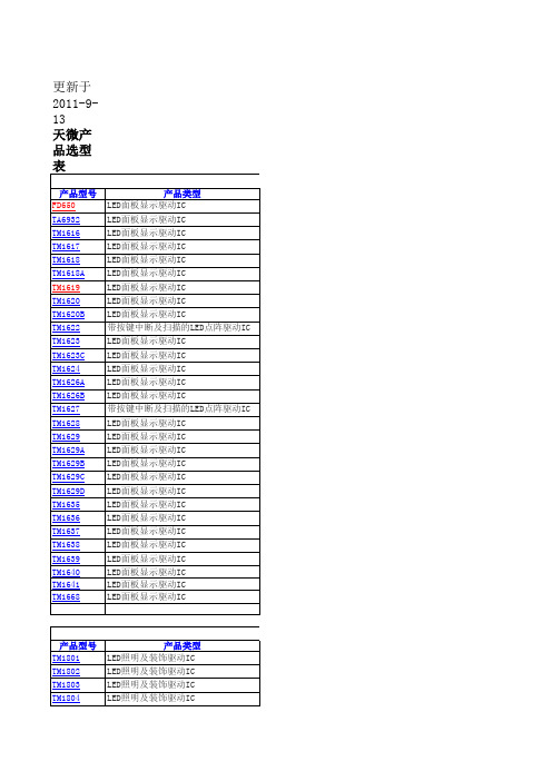
LED照明及装饰驱动IC LED照明及装饰驱动IC 照明及装饰驱动
特性描述 1路恒流驱动,15~45mA电流,端口耐压24V 输入电压1.5V,升压驱动,80~200mA电流 3路恒流驱动,单线级联,灰度256级可调 3路恒流驱动,单线级联,灰度2568级可调,工作电压6~24V 三通道LED恒流驱动,固定花样 输入电压3V~40V,6路60mA输出 12通道LED驱动IC 9通道LED,256级辉度可调 单通道LED,端口耐压24V 16通道LED驱动IC 12路(4段)恒压驱动,单线级联,灰度256级可调,工作电压6~24V
遥控器编码IC 遥控器编码IC 遥控器编码IC 遥控器编码IC 遥控器编码IC 遥控器编码IC 遥控器解码IC PIR红外控制IC PIR红外控制IC 固定码ID识别IC 固定码ID识别IC
产品型号 TM1108 TM7751 TM7752 TM7753 TM7755 TM7755S TM7757A TM7758 TM7759 TM7760 TM7762 TM9936 TM9937
产品类型 双路16位数模转换器 双8位CMOS乘法型数模转换器
产品型号 TM2312 TM2313
产品类型 数字音频处理电路 数字音频处理电路
TM2314
数字音频处理电路
产品型号 TM4101 TM72131
产品类型 锁相倍频IC 汽车收音机FM锁相环IC
产品型号 TM-SX670 TC1002
产品类型 微光电传感器 高性能细分步进马达控制IC
产品型号 M10N65 M12N60 M12N65 M1N60 M1N60A M1N60B M1N60C M1N65 M1N65A M1N65B
产品类型 10A,650V,N-Channel MOSFET 12A,600V,N-Channel MOSFET 12A,650V,N-Channel MOSFET 1A,600V,N-Channel MOSFET 1.5A,600V,N-Channel MOSFET 0.35A,600V,N-Channel MOSFET 1A,600V,N-Channel MOSFET 1A,650V,N-Channel MOSFET 1.5A,650V,N-Channel MOSFET 0.35A,650V,N-Channel MOSFET
LCD驱动芯片TM1621D『官方最新规格书』

80
150
5V VOL=0.5V
150
250
IOH2 LCD 公共口源电流 3V VOH=2.7V
-80
-120
5V VOH=4.5V
-120
-200
IOL3 LCD 段管脚漏电流 3V VOL=0.3V
60
120
5V VOL=0.5V
120
200
IOH3 LCD 段管脚源电流 3V VOH=2.7V
-40
-70
5V VOH=4.5V
-70
-100
RPH 上拉电阻
3V DATA,/WR, 40
80
5V /CS
30
60
TM1621D
3.0
V
5.0
V
mA
mA
mA
mA uA uA
uA uA
uA uA
uA
uA
150
Kohm
100
Kohm
交流电气特性
符号
描述
fSYS1
系统时钟
fSYS2 fSYS3 fLCD
BIAS 1/3
TOPT TNORMAL 注: X:0或1;
101
D
写数据到RAM
a5a4a3a2a1a0d0d1d2d3
10000000000X
C
关闭系统振荡器和LCD 偏压
发生器
10000000001X
C
打开系统振荡器
10000000010X
C
关闭LCD 偏压发生器
10000000011X
C
打开LCD 偏压发生器
I 负电源、地 I LCD 电源输入 I 正电源 O LCD 公共输出口
LCD1621(屏驱动)

RAM Mapping 32´4 LCD Controller for I/O mC
Features
· Operating voltage : 2.4V~5.2V · Built-in 256kHz RC oscillator · External 32.768kHz crystal or 256kHz
48 S E G 8 47 S E G 9 46 S E G 10 45 S E G 11 44 S E G 12 43 S E G 13 42 S E G 14 41 S E G 15 40 S E G 16 39 S E G 17 38 S E G 18 37 S E G 19 36 S E G 20 35 S E G 21 34 S E G 22 33 S E G 23 32 S E G 24 31 S E G 25 30 S E G 26 29 S E G 27 28 S E G 28 27 S E G 29 26 S E G 30 25 S E G 31
SEG 7 1 SEG 6 2 SEG 5 3 SEG 4 4 SEG 3 5 SEG 2 6 SEG 1 7 SEG 0 8
CS 9 R D 10 W R 11 D A TA 12 V S S 13 O S C O 14 O S C I 15 V LC D 16 V D D 17 IR Q 1 8 B Z 19 B Z 20 C O M 0 21 C O M 1 22 C O M 2 23 C O M 3 24
5
July 26, 1999
HT1621
Pad Description
Pad No. Pad Name
1
CS
2
RD
3
WR
4
TMCM-1021 硬件手册说明书

MODULE FOR STEPPER MOTORSTRINAMIC Motion Control GmbH & Co. KGHamburg, GermanyHardware Version V1.2HARDWARE MANUAL+ +TMCM-1021++U NIQUE F EATURES :Table of Contents1Features (3)2Order Codes (5)3Mechanical and Electrical Interfacing (6)3.1Size of Board (6)3.2Connectors (7)3.2.1Power, Communication and I/O Connector (8)3.2.2Motor Connector (8)3.3Power Supply (9)3.4Communication (10)3.4.1RS485 (10)3.5Inputs and Outputs (11)3.5.1Digital Inputs IN_0, IN_1, IN_2, IN_3 (11)3.5.2Outputs OUT_0, OUT_1 (12)4Reset to Factory Defaults (13)5On-board LED (13)6Operational Ratings (14)7Functional Description (15)8Life Support Policy (16)9Revision History (17)9.1Document Revision (17)9.2Hardware Revision (17)10References (17)1FeaturesThe TMCM-1021 is a single axis controller/driver module for 2-phase bipolar stepper motors with state of the art feature set. It is highly integrated, offers a convenient handling and can be used in many decentralized applications. The module can be mounted on the back of NEMA11 (28mm flange size) and has been designed for coil currents up to 0.7A RMS and 24V DC supply voltage. With its high energy efficiency from TRINAMIC’s coolStep™ technology cost for power consumption is kept down. The TMCL™ firmware allows for both, standalone operation and direct mode.M AIN C HARACTERISTICSHighlights-Motion profile calculation in real-time-On the fly alteration of motor parameters (e.g. position, velocity, acceleration)-High performance microcontroller for overall system control and serial communication protocol handling-For position movement applications, where larger motors do not fit and higher torques are not requiredBipolar stepper motor driver-Up to 256 microsteps per full step-High-efficient operation, low power dissipation-Dynamic current control-Integrated protection-stallGuard2 feature for stall detection-coolStep feature for reduced power consumption and heat dissipationEncoder-sensOstep magnetic encoder (max. 1024 increments per rotation) e.g. for step-loss detection under all operating conditions and positioning supervisionInterfaces-Up to 4 multi-purpose inputs (2 shared with outputs)- 2 general purpose outputs-RS485 2-wire communication interfaceSoftware-TMCL: s tandalone operation or remote controlled operation,program memory (non volatile) for up to 876 TMCL commands, andPC-based application development software TMCL-IDE available for free.Electrical and mechanical data-Supply voltage: +24V DC nominal (9… 28V DC)-Motor current: up to 0.7A RMS (programmable)Refer to separate TMCL Firmware Manual, too.TRINAMIC S U NIQUE F EATURES – E ASY TO U SE WITH TMCLstallGuard2™ stallGuard2 is a high-precision sensorless load measurement using the back EMF on thecoils. It can be used for stall detection as well as other uses at loads below those which stall the motor. The stallGuard2 measurement value changes linearly over a wide range of load, velocity, and current settings. At maximum motor load, the value goes to zero or near to zero. This is the most energy-efficient point of operation for the motor.Load [Nm]stallGuard2Initial stallGuard2 (SG) value: 100%Max. loadstallGuard2 (SG) value: 0Maximum load reached. Motor close to stall. Motor stallsFigure 1.1 stallGuard2 load measurement SG as a function of loadcoolStep ™coolStep is a load-adaptive automatic current scaling based on the load measurement via stallGuard2 adapting the required current to the load. Energy consumption can be reduced by as much as 75%. coolStep allows substantial energy savings, especially for motors which see varying loads or operate at a high duty cycle. Because a stepper motor application needs to work with a torque reserve of 30% to 50%, even a constant-load application allows significant energy savings because coolStep automatically enables torque reserve when required. Reducing power consumption keeps the system cooler, increases motor life, and allows reducing cost.00,10,20,30,40,50,60,70,80,9050100150200250300350EfficiencyVelocity [RPM]Efficiency with coolStepEfficiency with 50% torque reserveFigure 1.2 Energy efficiency example with coolStep2Order CodesTable 2.2 Order codesA cable loom set is available for this module:Table 2.5 Cable loom order code3Mechanical and Electrical Interfacing3.1Size of BoardThe board with the controller/driver electronics has an overall size of 28mm x 28mm in order to fit on the back side of a NEMA11 (28mm flange size) stepper motor. The printed circuit board outline is marked green in the following figure:PCB outlineR 2.5mmFigure 3.1 Board dimensions and position of mounting holes3.2ConnectorsThe TMCM-1021 has two connectors, an 8-pin power and input/output connector and a 4-pin motor connector (used to connect the attached motor).Power / Communication / IOs11MotorFigure 3.2 TMCM-1021 connectorsOverview of connector and mating connector types:Table 3.2 Connectors and mating connectors, contacts and applicable wire3.2.1Power, Communication and I/O ConnectorAn 8-pin CVIlux CI0108P1VK0-LF 2mm pitch single row connector is used for power supply, RS485 serial communication and additional multi-purpose inputs and outputs.Table 3.3 Power, communication and I/O connector3.2.2Motor ConnectorAn 4-pin CVIlux CI0104P1VK0-LF 2mm pitch single row connector is used for connecting the four motor wires to the electronics.Table 3.4 Motor connector3.3 Power SupplyFor proper operation care has to be taken with regard to power supply concept and design. Due to space restrictions the TMCM-1021 includes just about 20µF/35V of supply filter capacitors. These are ceramic capacitors which have been selected for high reliability and long life time. The module includes a 28V suppressor diode for over-voltage protection.C AUTION !Add external power supply capacitors!It is recommended to connect an electrolytic capacitor of significant size (e.g. 470µF/35V) to the power supply lines next to the TMCM-1021!Rule of thumb for size of electrolytic capacitor: In addition to power stabilization (buffer) and filtering this added capacitor will also reduce any power supply wires and the ceramic capacitors. In addition it will limit slew-rate of power supply stability problems with some switching power supplies.Do not connect or disconnect motor during operation!Motor disconnected / connected while energized. These voltage spikes might exceed voltage limits of power supply before connecting / disconnecting the motor.Keep the power supply voltage below the upper limit of 28V!Otherwise operating voltage is near the upper limit a regulated power supply is highly recommended. Please see also chapter 6, operating values.There is no reverse polarity protection!The transistors.TMCM-1021 V1.2 Hardware Manual (Rev. 1.02 / 2013-JUL-23)10 3.4Communication3.4.1RS485For remote control and communication with a host system the TMCM-1021 provides a two wire RS485 bus interface. For proper operation the following items should be taken into account when setting up an RS485 network:1.BUS STRUCTURE:The network topology should follow a bus structure as closely as possible. That is, the connection between each node and the bus itself should be as short as possible. Basically, it should be short compared to the length of the bus.termination resistor (120 Ohm)termination resistor (120 Ohm)Figure 3.5: Bus structure2.BUS TERMINATION:Especially for longer busses and/or multiple nodes connected to the bus and/or high communication speeds, the bus should be properly terminated at both ends. The TMCM-1021 does not integrate any termination resistor. Therefore, 120 Ohm termination resistors at both ends of the bus have to be added externally.3.NUMBER OF NODES:The RS485 electrical interface standard (EIA-485) allows up to 32 nodes to be connected to a single bus. The bus transceiver used on the TMCM-1021 units (SN65HVD3082ED) has just 1/8th of the standard bus load and allows a maximum of 256 units to be connected to a single RS485 bus.4.NO FLOATING BUS LINES:Avoid floating bus lines while neither the host/master nor one of the slaves along the bus line is transmitting data (all bus nodes switched to receive mode). Floating bus lines may lead to communication errors. In order to ensure valid signals on the bus it is recommended to use a resistor network connecting both bus lines to well defined logic levels. In contrast to the termination resistors this network is normally required just once per bus. Certain RS485 interface converters available for PCs already include these additional resistors (e.g. USB-2-485).terminationresistor(120 Ohm)RS485- / RS485BRS485+ / RS485AFigure 3.6 Bus lines with resistor network3.5 Inputs and Outputs3.5.1 Digital Inputs IN_0, IN_1, IN_2, IN_3The eight pin connector of the TMCM-1021 provides four general purpose inputs IN_0, IN_1, IN_2 and IN_3. The first two inputs have dedicated connector pins while the other two share pins with two general purpose outputs.All four inputs are protected using voltage resistor dividers together with limiting diodes against voltages below 0V (GND) and above +3.3V DC (see figure below).IN_0IN_1IN_2IN_3microcontroller and TMC262Figure 3.7 General purpose inputsThe four inputs have alternate functionality depending on configuration in software. The following functions are available:Table 3.5 Multipurpose inputs / alternate functionsAll four inputs are connected to the on-board processor and can be used as general purpose digital inputs.Using the alternate functionality of IN_0 and IN_1 it is possible to control the on-board stepper motor driver with the help of an external stepper motor controller using step and direction signals. For the step and direction signals the signal levels are the same as for the general purpose digital inputs.IN_3 can be used as analog input, also. A 12bit analog to digital converter integrated in the microcontroller will convert any analog input voltage between 0 and +6.6V to a digital value between 0 and 4095 then.3.5.2Outputs OUT_0, OUT_1The eight pin connector of the TMCM-1021 provides two general purpose outputs. These two outputs are open-drain outputs and can sink up to 100mA each. The outputs of the N-channel MOSFET transistors are connected to freewheeling diodes each for protection against voltage spikes especially from inductive loads (relais etc.).Both outputs OUT_0 and OUT_1 share pins with two of the four inputs (IN_2 resp. IN_3).Please take into account the 20k (2x 10k in series) resistance to ground (transistor not active) of the input voltage divider (figure 4.8) when designing the external “load” circuit.OUT_0 / IN_2OUT_1 / IN_3microcontrollerFigure 3.8 General purpose outputs4Reset to Factory DefaultsIt is possible to reset the TMCM-1021 to factory default settings without establishing a communication link. This might be helpful in case communication parameters of the preferred interface have been set to unknown values or got accidentally lost.For this procedure two pads on the bottom side of the board have to be shortened (see Figure 4.1).Please perform the following steps:1.Power supply off and USB cable disconnected2.Short two pads as marked in Figure 4.13.Power up board (power via USB is sufficient for this purpose)4.Wait until the on-board red and green LEDs start flashing fast (this might take a while)5.Power-off board (disconnect USB cable)6.Remove short between pads7.After switching on power-supply / connecting USB cable all permanent settings have been restoredto factory defaultsShort these two padsFigure 4.1 Reset to factory default settings5On-board LEDThe board offers one LED in order to indicate board status. The function of the LED is dependent on the firmware version. With standard TMCL firmware the green LED flashes slowly during operation.When there is no valid firmware programmed into the board or during firmware update the green LED is permanently on.Green LEDFigure 5.1 On-board LED6Operational RatingsThe operational ratings show the intended or the characteristic ranges and should be used as design values. In no case shall the maximum values be exceeded!Table 6.1 General operational ratings of module*) maximum setting for prototype and first versions of TMCL firmware. Will be adapted in firmware for series version.Table 6.2 Operational ratings of multi-purpose I/OsTable 6.3 Operational ratings of RS485 interface7Functional DescriptionThe TMCM-1021 is a highly integrated controller/driver module which can be controlled via RS485 interface. Communication traffic is kept low since all time critical operations (e.g. ramp calculations) are performed on board. The nominal supply voltage of the unit is 24V DC. The module is designed for both, standalone operation and direct mode. Full remote control of device with feedback is possible. The firmware of the module can be updated via the serial interface.In Figure 7.1 the main parts of the module are shown:-the microprocessor, which runs the TMCL operating system (connected to TMCL memory),-the power driver with its energy efficient coolStep feature,-the MOSFET driver stage, and-the sensOstep encoder with resolutions of 10bit (1024 steps) per revolution.9…Figure 7.1 Main parts of TMCM-1021The TMCM-1021 comes with the PC based software development environment TMCL-IDE for the Trinamic Motion Control Language (TMCL). Using predefined TMCL high level commands like move to position a rapid and fast development of motion control applications is guaranteed. Please refer to the TMCM-1021 Firmware Manual for more information about TMCL commands.8Life Support PolicyTRINAMIC Motion Control GmbH & Co. KG does not authorize or warrant any of its products for use in life support systems, without the specific written consent of TRINAMIC Motion Control GmbH & Co. KG.Life support systems are equipment intended to support or sustain life, and whose failure to perform, when properly used in accordance with instructions provided, can be reasonably expected to result in personal injury or death. © TRINAMIC Motion Control GmbH & Co. KG 2013Information given in this data sheet is believed to be accurate and reliable. However neither responsibility is assumed for the consequences of its use nor for any infringement of patents or other rights of third parties, which may result from its use.Specifications are subject to change without notice.All trademarks used are property of their respective owners.9Revision History9.1Document RevisionFigure 9.1 Document revision9.2Hardware RevisionFigure 9.2 Hardware revision10References[TMCM-1021] TMCM-1021 TMCL Firmware Manual [QSH2818-32-07-006] NEMA11 / 28mm bipolar stepper motor [QSH2818-51-07-012] NEMA11 / 28mm bipolar stepper motor [USB-2-485] USB-2-485 interface converter TRINAMIC manuals are available on .。
用HT1621驱动LCD的方法
用HT1621驱动LCD的方法HT1621是一种专门用于驱动液晶显示屏的电路芯片。
它主要由一个128x32位的RAM、一个系统控制单元、一个液晶电压驱动器和一个驱动信号产生器组成。
下面将详细介绍如何使用HT1621来驱动液晶显示屏。
首先,我们需要了解HT1621的引脚和功能。
HT1621具有36个I/O引脚,其中包括数据线D0-D15、片选线CS、读/写线WR、串行时钟线CLK、复位线RESET和外部时钟线CLOCK。
可以通过这些引脚来与HT1621进行通信和控制。
接下来,我们需要了解液晶显示屏的工作原理。
一般来说,液晶屏主要由一个像素矩阵和一个驱动电路组成。
驱动电路负责根据控制信号来控制像素的亮度。
液晶显示屏的像素矩阵可以根据需要进行修改,以显示所需的图形或文本。
基于以上原理,我们可以开始使用HT1621来驱动液晶显示屏。
以下是一个基本的步骤:1.连接电路:首先,将HT1621和液晶显示屏连接起来。
根据液晶显示屏的引脚分配表和HT1621的引脚分配表,进行正确的连接。
确保电路在工作时不会发生短路或其他问题。
2.初始化HT1621:在开始使用HT1621之前,需要执行一些初始化操作。
这包括设置像素矩阵的大小、选择使用的驱动模式(静态或动态)以及配置其他相关参数。
可以通过向HT1621发送一系列特定的配置命令来完成这些初始化操作。
3.发送数据:一旦HT1621完成初始化,就可以开始向液晶显示屏发送数据了。
可以通过编程将所需的图形或文本数据写入HT1621的RAM中。
注意,HT1621的RAM大小为128x32位,所以需要将图形或文本数据适当地分割和映射到RAM中的相应位置。
4.刷新液晶显示屏:一旦数据写入HT1621的RAM中,需要根据需要刷新液晶显示屏以显示所需的图形或文本。
可以通过向HT1621发送刷新命令来触发刷新操作。
HT1621将读取RAM中的数据并根据驱动电路的要求控制液晶显示屏中的像素亮度。
AIP1621 TM1621中微爱芯LCD显示驱动芯片
AiP1621A是一种128点阵式存储映射多功能LCD驱动电路。
AiP1621A的S/W结构特点,使它适合点阵式LCD显示,包括LCD模块和显示子系统,AiP1621A还具有节电功能。
主要特点:●工作电压:2.4V~5.5V●内部256KHz RC振荡器●外部32KHz晶振或256KHz频率输入●可选择1/2或1/3偏置和1/2、1/3或1/4占空比LCD显示●内部时基频率源●蜂鸣器驱动信号频率可选择2KHz或4KHz●具有关机指令可减少功耗●内部时基发生器和WDT看门狗定时器●内部时基或WDT溢出输出●八个时基/WDT时钟的时钟源●32×4 LCD驱动器●内部32×4bit显示RAM●四路串行接口●内部LCD驱动频率源●可用指令控制操作●数据模式和命令模式指令●R/W地址自动累加●三种数据访问模式●VLCD引脚用来调整LCD工作电压功能框图:注::芯片选择 BZ,:蜂鸣器输出,,DATA:串行接口COM0~COM3,SEG0~SEG31:LCD输出:时间基准或WDT溢出输出引脚排列图:应用线路概述TM1621是内存映象和多功能的LCD驱动器,TM1621的软件配置特性使它适用于多种LCD应用场合,包括LCD模块和显示子系统。
用于连接主控制器和TM1621的管脚只有4或5条,TM1621还有一个节电命令用于降低系统功耗。
功能特性工作电压2.4~ 5.2V内嵌256KHz RC 振荡器可外接32KHz晶片或256KHz频率源输入可选1/2或1/3偏压和1/2、1/3或1/4的占空比片内时基频率源蜂鸣器可选择两种频率节电命令可用于减少功耗内嵌时基发生器和看门狗定时器(WDT)时基或看门狗定时器溢出输出八个时基/看门狗定时器时钟源一个32x4的LCD 驱动器一个内嵌的32x4位显示RAM 内存四线串行接口片内LCD驱动频率源软件配置特征数据模式和命令模式指令三种数据访问模式提供VLCD管脚用于调整LCD操作电压封装形式:SSOP48、LQFP44结构图/CS 为片选信号线BZ,/BZ 声音输出/WR,/RD,DATA:串行接口COM0~COM3,SEG0~SEG31:LCD 输出/IRQ:时基或WDT溢出输出管脚图:TM1621_SSOP482管脚功能定义:3供应电压: -0.3V~0.5V 贮存温度:-50~125度输入电压: VSS-0.3V~VDD+0.3V 工作温度:-25~75度直流电气参数4交流电气特性:5应用图:主控制器与TM1621组成显示系统,参见下图注意: 1、VLCD的电压必须低于VDD电压;2、VR电阻用于调节VLCD输出电压,当VDD=5V,VLCD=4V,VR=15KΩ+20%3、R为外部上拉电阻,上拉到VDD,R=10KΩ+20%4、C1、C2 为外部晶振电容,建议值如下:晶振误差电容值(C1、C2)+10ppm 0~10p10~20ppm 10~20p系统结构:1、显示内存(RAM)静态显示内存(RAM)以32x4位的格式储存所显示的数据。
TEA1721DTN1,118;中文规格书,Datasheet资料
1.Product profile1.1General descriptionThe TEA1721 is a small and low cost module Switched Mode Power Supply (SMPS) controller IC for low power applications (up to 5 W) and operates directly from the rectified universal mains input. The device includes a high voltage power switch (700 V) and has been optimized for flyback converter topologies to provide high-efficiency over the entire load range with ultra-low power consumption in the no-load condition. It provides a circuit for start-up directly from the rectified mains voltage without any external bleeder circuits.The converter operates as a regulated voltage source from no-load up to the maximum output current and operates as current source that delivers the maximum current over a broad output voltage range. Using the TEA1721, a low power converter can be built at minimum cost and with the minimum number of external components.The controller regulates the output voltage with primary-side sensing which eliminates the need for an additional secondary feedback circuitry and simplifies the design. At higher power levels, a frequency and current control mode is used. It operates with Burst mode control at low power levels and no-load condition. The burst mode minimizes audible noise and provides an energy saver state which reduces the power consumption in no-load condition. The Burst mode frequency of 1270 Hz enables no-load power consumption below < 22 mW at high mains input.1.2Features and benefitsPower features:⏹Low power SMPS controller with integrated power switch designed for applications up to 5 W ⏹700 V high voltage power switch for global mains operation⏹Primary sensing for control of the output voltage without optocoupler and secondary feedback circuitry ⏹Minimizes audible noise in all operation modes ⏹USB battery charging and Energy Star 2.0 compliant⏹Jitter function for reduced EMITEA1721DTHV start-up flyback controller with integrated MOSFET for 5 W applications, 1270 Hz burst frequencyRev. 2.1 — 7 June 2012Product data sheetGreen features:⏹Enables no-load power consumption < 22 mW⏹Very low supply current in no-load condition with energy saver mode⏹Incorporates a high voltage start-up circuit with zero current consumption undernormal switching operation⏹Available in halogen-free and Restriction of Hazardous Substances (RoHS) SO7packageProtective functions:⏹OverVoltage Protection (OVP) on Feedback control (FB) pin with auto-restart⏹UnderVoltage LockOut (UVLO) protection on IC supply pin⏹OverTemperature Protection (OTP)⏹Soft-start by reduced peak current for zero and low output voltage⏹Demagnetization protection for guaranteed discontinuous conduction mode operation⏹Open and short-circuit protection of the Feedback control (FB) pin⏹Short-circuit protection of the charger output1.3Applications⏹Battery chargers for cellular phones and other low power adapters up to 5 W⏹Standby supply for TV and desktop PC⏹Power supply for White Goods applications1.4Quick reference dataTable 1.Quick reference dataSymbol Parameter Conditions Min Typ Max Unit Power switch (Pin: DRAIN)R DSon drain-sourceon-stateresistanceI ds = 30 mA; T j = 100 C 1315.5 17 ΩOscillator (Pins: DRAIN and SOURCE)f burst burst frequency burst frequency in CVB mode,without jitter1145 1270 1395 Hzf osc-high oscillatorfrequency High maximum switching frequencyin CV and CC mode, withoutjitter4850.553kHzSupply (Pin: VCC)V CC(startup) start-up supplyvoltage151719V V CC(stop) stopsupplyvoltageundervoltage lockout of IC 7.58.59.5V2.Ordering informationTable 2.Ordering informationType number PackageName Description Version TEA1721DT/N1SO7plastic small outline package; 7 leads; body width 3.9 mm SOT1175-13.Block diagram3.1Block diagram4.Pinning information4.1Pinning4.2Pin descriptionPin Pin name I/O type Pin description1GND1ground2GND2ground3GND3ground4FB I feedback input for voltage sensing5VCC I supply input6SOURCE O source for power switch7DRAIN I drain of power switch--high voltage spacer5.Functional description5.1Start-upThe TEA1721 starts up by charging the VCC capacitor until the V CC(start) level. Thecharging current flows from the high voltage DRAIN pin via an internal start-up currentsource to the VCC pin.Once the start level has been reached the start-up current source is switched off. Duringswitching operation, the start-up current source remains current-less and has zerobleeder loss.5.2Primary sensingThe FB input senses the reflected secondary voltage on the primary side. The FB inputhas a sample and hold function that samples the FB voltage on the secondary stroke tocontrol the output voltage.The sampled V FBS voltage is the input for the TEA1721’s control loop and defines theoperating mode.5.3Operating modesThe TEA1721 operates in three modes, one of which is active at the time. The threemodes in order of decreasing load impedance are:•CVB: Constant Voltage with Burst mode•CV: Constant Voltage mode•CC: Constant Current modeThe converter acts as a voltage source in CVB and CV modes.The converter acts as a current source in CC mode.5.3.1Constant Voltage with Burst mode (CVB)At low power, the TEA1721 operates in Burst mode.Burst mode operates with a V SOURCE = 100 mV, a switching frequency of 22.5 kHz andburst duty-cycle regulation by sensing the FB voltage.The TEA1721 features an energy save function that puts the main part of the analogueblocks in a sleep mode with low supply current in burst mode. The burst mode enables the energy save mode in the non-switching part of the burst. The IC switches to the nominal supply just before new burst starts.Transition from burst mode to CV mode happens at 100 % burst duty cycle: a burstcompletely filled with 32 pulses. This 100 % pulse train is identical to the lowest powerlevel of the CV mode. The TEA1721 changes directly from burst mode to CV mode if the FB voltage drops below 2.4 V in burst mode.5.3.2Constant Voltage mode (CV)At higher power levels, the TEA1721 operates in CV mode. The output voltage is sensed by the FB pin and the control keeps the output voltage constant over the power range.CV mode starts at 22.5 kHz switching frequency and I SOURCE regulation at the V SOURCEminimum level of 100 mV.With an increasing power output, the V SOURCE level and the switching frequency are also increased.CV mode is exited when the maximum power level is reached. Maximum power occurs atI SOURCE regulation at the V SOURCE maximum level of 555 mV and a maximum switchingfrequency of 50.5 kHz.5.3.3Constant Current mode (CC)The CC mode starts at maximum power delivery and keeps the output current constant for decreasing output voltage.CC mode is enabled when the converter is operating at the maximum switchingfrequency, with the maximum primary peak current when the FB voltage drops below the regulated level.CC mode operation controlled is by regulation of the switching frequency from 50.5 kHz down to 22.5 kHz and by I SOURCE regulation from the maximum V SOURCE level of 555 mV until level of V SOURCE is 0.21 V. The V SOURCE level of 0.21 V equals the level at start-up with zero output voltage and the output capacitor discharged or on a short-circuit of thecharger output.5.4JitterThe TEA1721 features a jitter function for ElectroMagnetic Interference (EMI) reduction.The switching frequency is 7% typical for the spread spectrum. The sweep frequency is a low frequency of approximately 200 Hz. To keep the output power constant, the V SOURCE level is jittered with the opposite polarity. The jitter is active in all operation modes except burst mode.6.Limiting values[1]Human body model: equivalent to discharging a 100 pF capacitor through a 1.5 k Ω series resistor.7.Thermal characteristicsTable 3.Limiting valuesIn accordance with the Absolute Maximum Rating System (IEC 60134).Symbol ParameterConditionsMin Max Unit T amb ambient temperature -40+85°C T j junction temperature -40+150°C T stg storage temperature-55+150°C V ESDelectrostatic discharge voltageCDM; all pins-500+500VHBM; all pins, except pin 7[1]-2000+2000V HBM; pin 7[1]-1000+1000V Voltages V DRAIN voltage on pin DRAIN -2+700V V SOURCE voltage on pin SOURCE -0.3+5V V CC voltage on pin VCC -0.3+35V V FB voltage on pin FB -20+5V Currents I DRAIN current on pin DRAIN -0.1+0.7A I SOURCEcurrent on pin SOURCE-0.7+0.1ATable 4.Thermal characteristicsSymbol Parameter ConditionsMin Typ Max Unit R th(j-a)thermal resistance from junction to ambientin free air; SO7 package; on open PCB of 2.2cm X 2.2cm; 2-layer; 70 µm Cu -136-K/W in free air; SO7 package; on open PCB of 3cm X 6cm; 1-layer; 35 µm Cu-136-K/W8.CharacteristicsTable 5.CharacteristicsV CC = 20 V; V FB = 0 V; R source = 1.5 Ω; T j-switch = 25 °C; T j-controller = 25 °C; all voltages referenced to GND, positive currents flow into the IC, unless otherwise specified.Symbol Parameter Conditions Min Typ Max Unit Supply (Pin: VCC)I CC(startup)0V start-up supply current V CC=0V-1.6-1.2-0.8mA I CC(startup)17V start-up supply current V CC = V CC(startup)-1.6-0.7-0.2mA I CC(energysave)supply current inenergy saveV FB = 2.8 V, non-switching90130170µAI CC(50kHz)supply current at50kHzin CC mode530750970µA V CC(startup)start-up supply voltage151719VV CC(stop)stop supply voltage undervoltage lockout of IC7.58.59.5VT otp overtemperatureprotection thresholdtemperature oncontroller die140150160°CT otp(hys)overtemperatureprotection temperaturehysteresis-50-°CFeedback (Pin: FB)V th(ovp)fbck feedback overvoltageprotection thresholdvoltage3.1 3.2 3.3VV ref(fbck)feedback referencevoltagein CV ode 2.5 2.55 2.6VV th(fbck)CV constant voltage modefeedback thresholdvoltagein burst mode operation 2.35 2.4 2.45VV th(det)demag(fb)demagnetizationdetection voltage levelon FB pin255075mVOscillator (Pins: DRAIN and SOURCE)f burst burst frequency burst frequency in CVB mode, withoutjitter1145 1270 1395 Hzf jit/f sw jitter frequency toswitching frequencyratio in all operation modes except in CVBmode579%f osc-high oscillator frequencyHigh maximum switching frequency in CVand CC mode, without jitter4850.553kHzf osc-low oscillator frequencyLow minimum switching frequency in CVand CC mode, without jitter. Switchingfrequency in CVB mode2122.524kHzf sweep jitter sweep frequency In current source operation150200250Hz δmax maximum duty cycle727578%Power switch (Pin: DRAIN)I drain(off)off-state drain current V DRAIN = 325 V-1-µA R DSon drain-source on-stateresistanceT j=25°C;I ds = 30 mA1315.517ΩV(BR)DS drain-sourcebreakdown voltage700--V Peak current comparator (Pin: SOURCE)t PD propagation delay time dV/dt=0.2V/µs-100-ns t leb leading edge blankingtime290325360nsV ref-peak-high reference voltage, highpeak voltage maximum peak voltage in CV and CCmodes, without jitter0.5250.5550.585VV ref-peak-low reference voltage, lowpeak voltagein CVB mode0.0850.10.115VV ref-0 V reference voltage atstart-up or 0 Vfeedback voltage in CC mode with V FBS = 0 V0.180.210.24VTable 5.Characteristics …continuedV CC = 20 V; V FB = 0 V; R source = 1.5 Ω; T j-switch = 25 °C; T j-controller = 25 °C; all voltages referenced to GND, positive currents flow into the IC, unless otherwise specified.Symbol Parameter Conditions Min Typ Max Unit9.Package outlineFig 3.Package outline SOT1175-1 (SO7)分销商库存信息: NXPTEA1721DT/N1,118。
LCD驱动集成电路TM1729规格书V1.0
--
最小值 -
2.5 0.6 1.3 100 100 1.3 0.6 0.6 0.6
TM1729 典型值
-
最大值 0.3 0.3 -
单位
us us us us us ns ns us us us us
8.4. 二线串行数据传输时间波形
SDA
t BUF
t LW
SCL
SDA
t HD:STA
tr
t SDH
SDA SCL
开始条件
停止条件
在利用2线I/F输入命令以及数据时必须形成开始条件和停止条件的固有形态发生。
Slave_Address S0 1111100AC
COMMAND
A C DISPLAY DATA A P
开始条件
ACK 命令或数据判定位
停止条件
本芯片在输入命令或显示数据时,必须按照以下步骤:
©Titan Micro Electronics
V1.0
2
6. 输入/输出等效电路
VDD
VDD
VLCD
GND
GND
52 SEG×4 COM LCD 驱动芯片 TM1729
VDD TEST1
GND
VDD TEST2
GND
SDA
SCL
VDD
OSCIO
GND
GND
GND
2. 功能特点
工作电压范围:2.5~5.5V 液晶驱动输出:52 SEG×4 COM 内置DDRAM显存容量:52×4=208bit 液晶驱动模式:1/3Bias、1/2Bias 液晶翻转模式:Line、Frame 串行数据输入接口:SCL、SDA 低功耗设计 内置振荡电路 搭载等待模式 内置上电复位功能 搭载闪烁模式 封装形式: TSSOP48,SSOP48,LQFP64
深圳天微1721驱动
/**版权信息:深圳天微技术部*文件名:TM1721*当前版本: 1.0*单片机型号:AT89S52*开发环境:Keil uVision3*晶震频率:12M*作者:李建文*完成日期:2008-6-19*功能:按键控制LCD屏显示0-9;以及全屏显示和全灭。
*/#include<reg52.h>#include<intrins.h>#define nop _nop_();#define uchar unsigned char#define uint unsigned int#define void delay_ms(uchar cyc);sbit stb =P1^0; //定义片选通讯口sbit clk =P1^1; //定义时钟通讯口sbit dio =P1^2; //定义数据输入/输出通讯口bdata unsigned char y=0;//定义可以位寻址全局变量ysbit y7 =y^7;unsigned char m,d,e,i;unsigned char w[4]={0xff,0xff};//------写数据给IC----------void write(uchar wr_data){uchar i;stb =0; //给有效的片选信号(片选信号是低电平有效)nop;nop;for(i=0;i<8;i++)//开始传送8位数据,每循环一次传送一位数据{clk =0;nop;nop;//delay_ms(200);wr_data >>= 1;//移位数据,低位在前!nop;dio = CY;nop;nop;//delay_ms(200);clk =1;//delay_ms(200);nop;}}//-------读按键数据--------unsigned char read(){stb = 0; //给有效的片选信号(片选信号是低电平有效)dio = 1; //这里必须置高,因为没有按键按下时,键值默认为00H,此时为了与键值有区别//unsigned char d;for(d=0;d<8;d++){clk = 0;if(dio==1){y7 = 1;}else{y7 = 0;}clk = 1;if(d!=7){y=(y>>1);}}return(y);}void delay_ms(uchar cyc){//当将=1的时候,延时1msuchar jj;for(jj=1;jj<=cyc;jj++){nop;}}//------显示子程序--------void xianshi(unsigned char p){unsigned char h;stb = 1;clk = 1;dio = 1;write(0x0c);//显示模式设置,stb = 1;write(0x40);//写数据到显示寄存器,采用地址自动加一stb = 1;write(0xc0);//显示寄存器的00H单元开始for(h=0;h<16;h++){write(p);//给显示寄存器送数据,}stb=1;write(0x92);//显示控制参数,点亮数码屏幕,亮度可以通过改变低三位调节}//-----判按键子程序-------void panjian(unsigned char k[4]){if((k[0]==0x02)){m=0x3f;} //当KS0与SEG29按键按下时候,数码管显示数字0 if((k[0]==0x04)){m=0x06;} //当KS0与SEG30按键按下时候,数码管显示数字1 if((k[0]==0x20)){m=0x5b;} //当KS1与SEG29按键按下时候,数码管显示数字2。
- 1、下载文档前请自行甄别文档内容的完整性,平台不提供额外的编辑、内容补充、找答案等附加服务。
- 2、"仅部分预览"的文档,不可在线预览部分如存在完整性等问题,可反馈申请退款(可完整预览的文档不适用该条件!)。
- 3、如文档侵犯您的权益,请联系客服反馈,我们会尽快为您处理(人工客服工作时间:9:00-18:30)。
功能
01
00
01
0 1 数据读写模式
10
设置
无关项, 填0
11
01
0
地址增加模式
01
1
设置
01
0
测试模式设置
01
1
(内部使用)
说明
写数据到显示寄存器 写数据到 PWM 寄存
器 读键扫数据 读 SW 开关输入口数
据 自动地址增加
固定地址 普通模式 测试模式
©Titan Micro Electronics V1.2
TM1721
b5b4 00 01 10 11
PWM输出口/段输出设置 SG20、 SG21、SG22、 SG23 SG20、SG21、SG22、 PWM3 SG20、SG21、PWM2、PWM3 PWM0、PWM1、PWM2、PWM3
b3b2 按键输入/段输出设置
00
SG28、SG29、SG30、SG31
COM0 COM1 COM2 COM3 SEG0 SEG1
NC SEG2 SEG3 SEG4 SEG5 SEG6 SEG7 SEG8 SEG9 SEG10 SEG11 SEG12 SEG13 SEG14 SEG15 SEG16 SEG17 SEG18
48 47 46 45 44 43 42 41 40 39 38 37 36 35 34 33 32 31 30 29 28 27 26 25
2、 该寄存器存储通过串行接口从TM1721的读取数据,地址分配如下:
KEY0/ KEY1/ KEY2/ KEY3/ KEY0/ KEY1/ KEY2/ KEY3/ SG28 SG29 SG30 SG31 SG28 SG29 SG30 SG31
KS0
KS1
00H
KS2
KS3
01H
KS4
KS5
02H
Bit0
Bit1
Bit2
Bit3
Bit4
Bit5
Bit6
Bit7
位
地址
图(3)
▲注意:1、TM1721最多可以读3个字节,不允许多读。 2、读数据字节只能按顺序从BYTE1-BYTE3读取,不可跨字节读。例如:硬件上的KEY2与KS5对应按键按下
时,此时想要读到此按键数据,必须需要读到第3个字节的第6BIT位,才可读出数据; 当KEY1与KS5,KEY2与KS5,KEY3与KS5三个按键同时按下时,此时BYTE3所读数据的B5,B6,B7位均为1。
©Titan Micro Electronics V1.2
1
LFQP48
LCD 驱动控制专用电路
TM1721
©Titan Micro Electronics V1.2
2
管脚功能定义
LCD 驱动控制专用电路
TM1721
符号
DIO
引脚名称
B7
B6
指令
0
0
显示模式设置
0
1
数据命令设置
1
0
显示控制命令设置
1
1
地址命令设置
如果在指令或数据传输时STB被置为高电平,串行通讯被初始化,并且正在传送的指令或数据 无效(之前传送的指令或数据保持有效)。
©Titan Micro Electronics V1.2
6
LCD 驱动控制专用电路
高位 低位
00
PWM0
XXb5b4_b3b2b1b0
01
PWM1
XXb5b4_b3b2b1b0
10
PWM2
XXb5b4_b3b2b1b0
11
PWM3
XXb5b4_b3b2b1b0
PWM0-PWM3寄存器数据说明
b5b4_b3b2b1b0
PWM脉冲宽度设定
00H
恒为0
01H~3EH
1/64~62/64
SW0/SEG24 SW1/SEG25 SW2/SEG26 SW3/SEG27 KEY0/SEG28 KEY1/SEG29 KEY2/SEG30 KEY3/SEG31
KS0~KS5
段输出
PWM输出 /段输出 复合端口
通用输入/ 段输出
复合端口
按键输入/ 段输出
复合端口
键扫输出
VDD GND
电源 地
NC
3、组合键只能是同一个KS,不同的KEY引脚才能做组合键;同一个KEY与不同的KS引脚不可以做成组合键 使用。
©Titan Micro Electronics V1.2
5
端口控制寄存器
LCD 驱动控制专用电路
TM1721
1、PWM寄存器说明
地址(B1B0) 寄存器名称
1、工作模式设置
工作模式设置好后,不允许在使用中切换工作模式。
MSB
LSB
0 0 b5 b4 b3 b2 b1 b0
b1b0 00 01 10 11
通用输入口/段输出设置 SG24、SG25、SG26、SG27 SG24、SG25、SG26、SW3 SG24、SG25、SW2、SW3 SW0、SW1、SW2、SW3
显示地址
00H 01H 02H 03H 04H 05H 06H 07H 08H 09H 0AH 0BH 0CH 0DH 0EH 0FH
TM1721
b3b2b1b0:显示寄存器/背光驱动设置寄存器的地址 该指令用来设置显示寄存器或背光驱动设置寄存器的地址。上电时,地址设为00H。
设置显示寄存器的地址,当地址设为10H 或更高,数据被忽略,直到有效地址被设定 (00H~0FH)。
COM0
Bit0
COM1 COM2
SEG0
SEG2
SEG4
SEG6
SEG8
SEG10
SEG12
SEG14
SEG16
SEG18
SEG20
SEG22
SEG24
SEG26
SEG28
SEG30
Bit1
Bit2
COM3
Bit3
COM0
Bit4
COM1 COM2
SEG1
SEG3
SEG5
SEG7
SEG9
SEG11
01
SG28、SG29、SG30、KEY3
10
SG28、SG29、KEY2、KEY3
11
KEY0、KEY1、KEY2、KEY3
该指令用来设置工作模式,上电后,初始状态为b5b4b3b2b1b0=000000
2、数据设置
该指令用来设置数据写和读。
MSB
LSB
B7 B6 B5 B4 B3 B2 B1 B0
4、显示控制
MSB 10
LSB 0 b4 b3 b2 b1 b0
b4:显示开关设置位;为1显示开,为0显示关
b3:LCD驱动偏压设置位;为1设为1/2偏压;为0设为1/3偏压
b2b1b0:LCD工作电压设置位;
当b2b1b0=111时,工作电压=VCC(VCC为芯片的工作电压)。当VCC=5V,b3=1的时候 (1/2偏压),调节电压的范围约2.24V-5V;b3=0(1/3偏压),调节电压的范围约是2.88-5V。
4
按键与按键寄存器
LCD 驱动控制专用电路
1 、键扫矩阵为6×4bit,如下所示:
TM1721
KS5 KS4 KS3 KS2 KS1 KS0
KEY0
KEY1
KEY2
KEY3
图(2) 键扫数据储存地址如下所示,先发读键命令后,开始读取按键数据BYTE1—BYTE3字节,读数 据从低位开始输出。芯片KEY(0—3)和KS引脚对应的按键按下时,相对应的字节内的 BIT位为1。
LCD 驱动控制专用电路
TM1721
概述
TM1721是一种带键盘扫描接口的LCD驱动控制专用电路,内部集成有MCU 数字接口、数据 锁存器、LCD驱动、键盘扫描、幻彩背光驱动等电路。本产品性能优良,质量可靠,无须更改解码 板底层指令,与现有LED驱动IC的指令集完全兼容。现有的支持LED显示的解码板可以直接外接LCD 显示前面板,不需要外加单片机进行按键扫描(或通过解码板扫描按键),不需要另外用HT6221 作按键扫描。同时支持PWM背光驱动和SW普通输入扩展口。主要应用于VCR、VCD、DVD 及家 庭影院等产品的显示屏驱动。
特性说明
采用低功耗CMOS工艺 32X4点LCD驱动 6X4按键输入 4路LED驱动,具有64级PWM,可用于LCD幻彩背光驱动; 4通用输入口,可连接拨轮式电子编码开关 1/2或1/3LCD驱动偏压可选 LCD工作电压可调 串行接口(CLK,STB,DIO) 振荡方式:内置RC振荡,典型振荡频率为128KHZ 封装形式:SSOP48,LFQP48
3
LCD 驱动控制专用电路
VCC
TM1721
芯片内部电路
CT
10K DIO
GND
图(1)
显示寄存器
该寄存器存储通过串行接口从外部器件传送到TM1721 的数据,地址从00H-0FH共16字节单 元,分别与芯片SGE和COM管脚所接的LCD灯对应,分配如下图: 写LCD显示数据的时候,按照从显示地址从低位到高位,从数3 4 5 6 7 8 9 10 11 12 13 14 15 16 17 18 19 20 21 22 23 24
VDD DIO CLK STB GND KS0 KS1 KS2 KS3 KS4 KS5 SEG31/KEY3 SEG30/KEY2 SEG29/KEY1 SEG28/KEY0 SEG27/SW3 SEG26/SW2 SEG25/SW1 SEG24/SW0 SEG23/PWM3 SEG22/PWM2 SEG21/PWM1 SEG20/PWM0 SEG19
空脚