ABB变频器ACS580说明书
ABB变频器操作说明书

防水防潮
避免变频器受到雨淋或潮湿环境的影响,以 免引起电气故障。
定期检查和预防性维护计划制定
定期检查
建议每季度对变频器进行一次全 面检查,包括外观、接线、功能 等方面。
预防性维护计划
根据变频器的使用情况和环境, 制定预防性维护计划,包括清洁 、紧固、润滑、更换易损件等。
故障排查
如果发现变频器出现故障或异常 情况,应立即停机检查,并联系 专业人员进行维修。
产品升级和扩展方案推荐
软件升级
随着技术的不断进步,ABB会不断推出新的 软件版本,建议用户及时升级软件,以获得 更好的性能和功能。
硬件扩展
如果用户的负载增加或需要更高的性能,可以考虑 对变频器进行硬件扩展,如增加功率模块、通讯模 块等。
定制化服务
如果用户有特殊的需求或应用场景,可以联 系ABB提供定制化服务,以满足用户的个性 化需求。
PART 05
故障诊断与排除指南
常见故障类型及原因分析
过流故障
变频器输出电流超过设定值,可能原因 包括电机过载、电机短路、输出电缆短
路等。
欠压故障
变频器输入电压低于设定值,可能原 因包括电源电压过低、电源缺相、整
流桥故障等。
过压故障
变频器输出电压超过设定值,可能原 因包括电源ቤተ መጻሕፍቲ ባይዱ压过高、减速时间过短 、负载惯性过大等。
XX
REPORTING
2023 WORK SUMMARY
THANKS
感谢观看
PART 02
ABB变频器产品介绍
ABB变频器系列概述
ACS880系列
高性能、多功能的变频器,适用于各种工业应用。具有先 进的控制算法和丰富的功能选项,可实现高精度、快速响 应的速度和转矩控制。
ACS580MV说明材料DriveComposer快速指导CN

§ 在PC和控制盘之间,USB电缆连接 § 使用控制盘:
§ USB-to-RJ45-to-RS485 § 不再使用额外的通讯卡
§ 可选不用控制盘
§ USB-to-RS485 § 专用USB转RS485电缆
USB (’mini B’ type)
© 北京ABB电气传动系统有限公司,培训中心
Drive Composer 简单易用
§ 为通用传动设计,方便监控和维护传动 § 2个版本:
§ Drive composer entry – 入门版,免费 § Drive composer pro – 专业版,更多功能
§ 两种版本都适用于通用传动,比如:ACS880、ACS580、ACS580MV
北京ABB电气传动系统有限公司,培训中心
ACS 580MV 服务和调试
Drive Composer
Drive Composer 培训目标
完成本单元培训,您将可以使用Drive Composer:
§ 保存参数 § 比较/恢复参数 § 读取和保存故障日志 § 初始化和保存dataloggers § 保存工作界面 § 检查控制框图 § 创建支持包 § 参数转换(适用于低压传动软件升级)
Drive Composer 创建支持包
© 北京ABB电气传动系统有限公司,培训中心
Drive Composer pro 参数转换(适用于低压传动软件升级)
© 北京ABB电气传动系统有限公司,培训中心
© 北京ABB电气传动系统有限公司,培训中心
§ 网络:通过以太网转换器连接
以太网
单独的转换器
§ 网络:通过以太网总线适配器连接
以太网
© 北京ABB电气传动系统有限公司,培训中心
ACS580_04硬件手册

ACS580_880-modbus guide

ACS580/880 Modbus RTU 调试指导
本文介绍了设置变频器实现总线通讯控制的速度/转矩控制方法。
本文介绍的仅仅是实现操作功能的基本步骤,如果需要其他功能请参阅相关手册.
实现的功能:通过总线控制切换EXT1/EXT2,EXT1用来实现速度控制,EXT2用来实现转矩控制.
使用的硬件:ACS580/880变频器
调试步骤:
1.将变频器硬件准备好,电源线,通讯线连接好(参见相关手册)
2.正确设置电机参数,电压,电流,转速等(参见相关手册)
4.设置完毕后即可通过上位机控制变频器的起停,给定:
变频器转速模式启动:向modbus寄存器40001写入十六进制047Fh
变频器停止:向modbus寄存器40001写入十六进制047Eh
变频器转矩模式启动: 向modbus寄存器40001写入十六进制0C7Fh
速度给定:向modbus寄存器40002写入相应速度,十进制20000对应最高给定转速(参数46.01)使电机反转只需写入负值即可
转矩给定:向modbus寄存器地址40003写入相应转矩,十进制10000对应最大给定转矩(参数46.03),使转矩反向写入负值即可(310,510无转矩模式)
读当前转速:读modbus寄存器40101
读母线电压:读modbus寄存器40111
读输出电流:读modbus寄存器40107
故障复位:向Modbus寄存器40001写入十六进制04FEh.
完整的modbus寄存器地址定义参见相关变频器手册
MODBUS数据帧举例:
启动变频器:如变频器5302=1(变频器modbus站号为1),应发送:
读取输出转速(百分比形式): 如变频器5302=1(变频器modbus站号为1),应发送:。
ACS580变频器参数设置

ABB变频器(ACS580)参数设定参数码参数名称参数设定值备注96.01语言(2052)简体中文96.04应用宏(1)ABB标准宏99.06电机额定电流287.8A99.07电机额定电压380V99.08电机额定频率50Hz99.09电机额定速度1018.5N.m99.1电机额定功率160KW99.16电机相位顺序(0)正常(1)反转方向10.24RO1信号源(7)运行根据图纸接线位置设定10.27RO2信号源(7)运行10.3O RO3信号源(14)故障12.15AI1单位选择(2)V/mA(10)12.17AI1最小值0V12.18AI1最大值10V12.19AI1最小换算值5Hz12.2AI1最大换算值50Hz12.25AI2单位选择(10)mA12.27AI2最小值4mA12.28AI2最大值20mA12.29AI2最小换算值5HZ12.3O AI2最大换算值50HZ13.12AO1信号源(3)输出频率根据图纸上要求设定13.17AO1信号源最小值0HZ13.18AO1信号源最大值50HZ13.19AO1最小输出值4mA13.2AO1最大输出值20mA13.22AO2信号源(4)电机电流13.27AO2信号源最小值0A13.28AO2信号源最大值287.8A13.29AO2最小输出值4mA13.3O AO2最大输出值20mA19.11外部指令1、外部指令2选择(4)DI220.01外部命令1(1)启动停止20.06外部命令2(1)启动停止30.11最小速度0N.m 30.12最大速度1018.5N.m 30.13最小频率0HZ30.14最大频率50HZ31.19电机缺相(0)无动作31.2O接地故障(1)报警31.21输入缺相(0)无动作。
acs580参数手册
参数组一览表组内容页码01 实际值传动监测用基本信号。
11103 输入给定接收自各信号源的给定值。
11304 报警和故障最后发生的警告和故障信息。
11305 诊断传动维护相关的各运行时类型计数器和测量值。
11406 控制和状态字传动控制字和状态字。
11507 系统信息传动硬件和固件信息。
11910 标准 DI、RO数字输入和继电器输出的配置。
11911 标准 DIO、FI、FO频率输入的配置。
12212 标准 AI标准模拟输入配置。
12313 标准 AO标准模拟输出配置。
127 15 I/O 扩展模块安装在插槽 2 中的 I/O 扩展模块的配置。
133 19 运行模式外部控制位置源和运行模式选择。
138139 20 启动/停止/方向启动/停止/方向和运行/启动/点动允许信号源选择;正/负给定允许信号源选择。
21 启动/停车模式启动和停车模式;急停模式和信号源选择;直流励磁设置。
14722 速度给定选择速度给定选择;电动电位器设置。
15223 速度给定斜坡速度给定斜坡设置(为传动的加速率和减速率编程)。
15924 速度给定条件速度误差计算;速度误差窗口控制配置;速度误差步阶。
16225 速度控制速度控制器设置。
16326 转矩给定链转矩给定链设置。
167 28 频率给定控制链频率给定控制链设置。
17030 限值传动操作限制。
17831 故障功能配置外部事件;选择故障情况下传动的行为。
18232 监控信号监测功能 1...3 配置。
188 34 定时功能定时功能的配置。
192198 35 电机热保护电机热保护设置,如温度测量配置、负载曲线定义和电机风机控制配置。
36 负载分析器峰值和幅度记录器设置。
20537 用户负载曲线用户负载曲线的设置。
20740 过程 PID 参数集 1过程 PID 控制参数值。
21041 过程 PID 参数集 2过程 PID 控制的第二组参数值。
21943 制动斩波器内部制动斩波器的设置。
abbacs580485通讯参数设置

abbacs580485通讯参数设置摘要:I.引言A.概述B.目的C.背景II.参数设置A.参数概述B.重要参数1.波特率2.数据位3.停止位4.奇偶校验C.参数设置方法1.手动设置2.自动设置III.参数设置的影响A.通信质量B.数据传输速度C.网络稳定性IV.结论A.总结B.建议C.展望正文:Abbacs580485 通讯参数设置是确保通信设备之间正常通信的关键步骤。
正确的参数设置可以保证通信质量,提高数据传输速度,同时增强网络的稳定性。
本文将详细介绍abbacs580485 通讯参数设置的相关内容。
首先,我们需要了解参数设置的概述。
在abbacs580485 通信中,参数设置主要包括波特率、数据位、停止位和奇偶校验等关键参数。
这些参数对于保证通信的顺畅进行至关重要。
其次,我们将详细讨论这些参数的重要性。
首先是波特率,它是指通信设备之间数据传输的速率。
通常情况下,波特率越高,数据传输速度就越快。
然而,过高的波特率可能会导致数据丢失,因此需要根据实际需求进行合理设置。
其次是数据位,它是指每次数据传输中实际传输的数据位数。
数据位的设置应根据实际应用场景进行选择,以保证数据传输的准确性和完整性。
停止位是指在数据传输过程中,用于表示数据传输结束的位数。
合理的停止位设置可以有效避免数据丢失和传输错误。
最后是奇偶校验,它是一种检验数据传输是否正确的机制。
通过在数据传输过程中加入奇偶校验位,可以确保数据在传输过程中的正确性。
接下来,我们将介绍如何进行参数设置。
参数设置可以分为手动设置和自动设置两种。
手动设置需要用户根据实际需求,逐个调整参数。
而自动设置则通过预设的算法,自动调整参数以满足实际需求。
自动设置更加简便易行,适用于大多数场景。
最后,我们来谈谈参数设置的影响。
正确的参数设置可以保证通信质量,提高数据传输速度,同时增强网络的稳定性。
相反,错误的参数设置可能导致通信中断、数据丢失等问题。
因此,在进行abbacs580485 通讯参数设置时,我们需要充分考虑实际需求,确保参数设置的合理性。
ACS580-0P 3R 农业用水包装驱动程序补充到 ACS580-U1 用户手册说明书
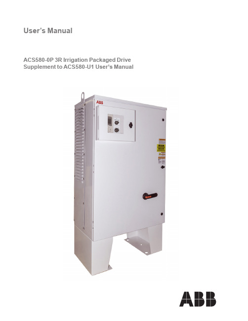
User’s ManualACS580-0P 3R Irrigation Packaged Drive Supplement to ACS580-U1 User’s Manual2 ACS580-0P 3R Irrigation Packaged Drive ACS580 Drive Manuals© 2020 ABB Inc. All Rights Reserved.ACS580-0P 3R Irrigation Packaged Drive 3Table of ContentsTable of ContentsSafetyUse of Warnings and Notes ..............................................4InstallationApplication .......................................................................5Input Disconnect Features and Functions ........................5Installation Flow Chart ......................................................7Preparing for Installation ..................................................8Installing the Drive ...........................................................10Mounting optional foot kit on 3R irrigation panel ...............13Installing the Wiring ........................................................16Typical Control Schematic ................................................19Application Guides - Hand - Auto MacroRatings ............................................................................22Input Power Connections and Terminals ..........................23Dimensions and Weights .................................................24Ambient Conditions ..........................................................25Applicable StandardsMaintenance Intervals ......................................................27Drive Module Fan Replacement (27)4 ACS580-0P 3R Irrigation Packaged DriveSafetySafetyWARNING! The ACS580 adjustable speed AC drive with Input Disconnect should ONLY be installed by a qualified electrician.WARNING! Even when the motor is stopped, dangerous voltage is present at the Power Circuit terminals U1, V1, W1 and U2, V2, W2 and, depending on the frame size, UDC+ and UDC-, or BRK+ and BRK-.WARNING! Dangerous voltage is present when input power is connected. After disconnecting the supply, wait at least 5 minutes (to let the intermediate circuit capacitors discharge) before removing the cover.WARNING! Even when power is removed from the input terminals of the ACS580, there may be dangerous voltage (from external sources) on the terminals of the relay outputs.WARNING! When the control terminals of two or more drive units areconnected in parallel, the auxiliary voltage for these control connections must be taken from a single source which can either be one of the units or an external supply.WARNING! The ACS580 will start up automatically after an input voltage interruption if the external run command is on.WARNING! When the ACS580 with Input Disconnect is connected to the line power, the Motor Terminals T1, T2, and T3 are live even if the motor is notrunning. Do not make any connections when the ACS580 with Input Disconnect is connected to the line. Disconnect and lock out power to the drive before servicing the drive. Failure to disconnect power may cause serious injury or death.Note! For more technical information, contact the factory or your local ABB sales representative.Use of Warnings and NotesThere are two types of safety instructions throughout this manual:• Notes draw attention to a particular condition or fact, or give information on a subject.• Warnings caution you about conditions which can result in serious injury or death and/or damage to the equipment. They also tell you how to avoid the danger. The warning symbols are used as follows:Dangerous voltage warning warns of high voltage which can cause physical injury and/or damage to the equipment.General warning warns about conditions, other than those caused by electricity,which can result in physical injury and/or damage to the equipment.ACS580-0P 3R Irrigation Packaged Drive 5InstallationInstallationStudy these installation instructions carefully before proceeding. Failure to observe the warnings and instructions may cause a malfunction or personal hazard.WARNING! Before you begin read “Safety” on page 1.WARNING! When the ACS580 with Input Disconnect is connected to the line power, the Motor Terminals T1, T2, and T3 are live even if the motor is notrunning. Do not make any connections when the ACS580 with Input Disconnect is connected to the line. Disconnect and lock out power to the drive before servicing the drive. Failure to disconnect power may cause serious injury or death.ApplicationThis manual contains supplemental information that is unique to ACS580 inputdisconnect configurations (0P). Refer to the base manual, ACS580-01 User’s Manual, for all other information.Input Disconnect Features and FunctionsThe ACS580 with Input Disconnect is an ACS580 AC adjustable frequency drivepackaged with an input disconnect switch and with a door mounted, external operating handle. The operating handle can be padlocked in the OFF position (padlock not supplied). Enclosure are UL Type 3R (NEMA 3R). The following is a typical power diagram.3 Phase6 ACS580-0P 3R Irrigation Packaged DriveInstallation The following figures show the front view of the ACS580 Drive with Input Disconnect standard configurations, and identify the major components.UL Type / NEMA 3R EnclosuresOperatingHandle forDisconnectSwitchNote! UL Type 3R enclosures are designed to be mounted on a wall. See section “Prepare the UL Type 3R ACS580 for UNISTRUT® mounting” for more details.ACS580-0P 3R Irrigation Packaged Drive 7InstallationInstallation Flow ChartThe installation of Input Disconnect configurations for ACS580 drives follows the outline below. The steps must be carried out in the order shown. At the right of each step are references to the detailed information needed for the correct installation of the unit.Note! References in the middle column below are to the ACS580-01 User’s Manual. References in the third column below are to this manual.8 ACS580-0P 3R Irrigation Packaged DriveInstallationPreparing for Installation (Supplement to ACS580-01 User’s Manual)Lifting the DriveACS580-0P 3R Irrigation Packaged Drive 9InstallationPreparing for Installation (Supplement to ACS580-01 User’s Manual)Drive IdentificationTo identify the type of device you are installing, refer to the type code number on the device identification label.• Wall mounting base drives – label attached on the side surface of the heat sink.• Packaged drive – label attached to outside surface on the left side of the enclosure.• Enclosure with hinged cover/door – label on inside surface of the cover/door.Type Code NumberUse the following to interpret the type code found on the identification label.Ratings and Frame SizeCharts in the “Ratings” sections of the ACS580-01 User’s Manual and this manual list technical specifications, and identify the drive’s frame size.Note! Some instructions in this document vary, depending on the drive’s frame size. To read the Ratings table, you need the “Output current rating” entry from the type code (see above).Suitable Mounting LocationFor selecting a suitable mounting location for configurations, refer to:•Preparing for installation in the ACS580-01 User’s Manual, and• The Technical Data section of this manual for information on dimensions, weights and free space requirements.Product seriesConstructionSizeVoltageOptionsConstruction0P = Drive Package with Disconnect Switch and Drive FusesSize(Output current rating, see table below for details)NOTE: Cabinet drives five (5) digit amp rating and type code2 = 208/240 VAC 4 = 460 VACStandard (Plus code)UL type 3R enclosure with flange mounted drive, Service Entrance rated for three phase four wire power system, input voltage surge suppressor and condensation heaterOption codesLetter code followed by 3 digit number (see option code pages for details)10 ACS580-0P 3R Irrigation Packaged DriveInstallationInstalling the Drive (Supplement to ACS580-01 User’s Manual)WARNING!Metal shavings or debris in the enclosure can damage electrical equipment and create a hazardous condition. Where parts, such as conduit plates require cutting or drilling, first remove the part. If that is not practical, cover nearby electrical components to protect them from all shavings or debris.Do not connect or disconnect input or output power wiring, or control wires, when power is applied.Never connect line voltage to drive output Terminals T1, T2 and T3.Do not make any voltage tolerance tests (Hi Pot or Megger) on any part of the unit. Disconnect motor wires before taking any measurements in the motor or motor wires.Make sure that power factor correction capacitors are not connected between the drive and the motor.Prepare the Mounting LocationThe ACS580 should only be mounted where all of the requirements defined in “Preparing for Installation” are met.Mount the Drive1. Use a hoist to move the cabinet into position.Note! If the cabinet location does not provide access to the cabinet sides, be sure to re-mount side panels before positioning cabinet.2. Install and tighten mounting bolts.Installing the Drive - continuedPrepare the UL Type 3R ACS580 for UNISTRUT ® mounting or wall mountingThe ACS580 UL Type 3R cabinet frame sizes are designed to be mounted on a solidvertical surface or using UNISTRUT. An optional floor/ground mounting kit is available forpurchase.Installing the Wiring (Supplement to ACS580-01 User’s Manual)Wiring RequirementsRefer to the “Wiring Requirements” Section in the ACS580-01 User’s Manual. Therequirements apply to all ACS580 drives. In particular:• Use separate, metal conduit runs for the following different classes of wiring: – Input power wiring.– Motor wiring.– Control/communications wiring.• Properly and individually ground the drive, the motor and cable shields.WALL MOUNTBACK VIEWInstalling the Drive - continuedOptional Floor/Ground Mounting KitAn optional floor/ground mounting kit is available for purchase.FLOOR PLAN LAYOUTGRADE 5 OR BETTERF R O M L E F T S U R F A C E O F E N C L O S U R E.62 7.22 24.78 31.38Step 1Prepare mounting surface for enclosure.Step 2back, drill the (10) holes as drill bit.Assembly instructions for mounting optional foot kit on 3R irrigation panelHW1001A38(24) REQ'D.Step 3Remove the vent plate on the right side of the enclosure to be able to assemble the hardware for the mounting feet.The vent plate can be remounted using two screws for safe keeping.Step 4Assemble foot kit with mounting hardware.Assembly instructions for mounting optional foot kit on 3R irrigation panelStep 5Using the lifting eyes, lift the enclosure and place onto mounting studs and assemble hardware.Assembly instructions for mounting optional foot kit on 3R irrigation panelWiring OverviewPower Connection – Standard Drive with Input Disconnect (Wall Mounted)The following figures show the Standard Drive with Input Disconnect (wall mounted) typical layout. (Refer to the ACS580-01 User’s Manual and 3R Irrigation Control Schematic for control connections to the drive.)Install the Line Input WiringLine Input Connections – Standard Drive with Input Disconnect Configurations Connect input power to the terminals of the disconnect switch. Connect the equipment grounding conductor to the ground lug. The figure below shows typical connection points for Standard ACS580 Drive with Input Disconnect configurations.WARNING! Check the motor and motor wiring insulation before connectingthe ACS580 to line power. Follow the procedure in the ACS580-01 User’s Manual. Before proceeding with the insulation resistance measurements, check that the ACS580 is disconnected from incoming line power. Failure to disconnect line power could result in death or serious injury.Note! For the remainder of the installation and start-up (motor and control wiring) refer to the ACS580-01 User’s Manual.CUSTOMER SUPPLIED WIRING*Typical ACS580 3R irrigation panel layoutTypical Control SchematicCUSTOMER SUPPLIED WIRINGACS580-0P 3R Irrigation Packaged Drive 21Application GuidesApplication Guides - Hand - Auto Macro3)max.500 ohmNotes:1.The signal source is powered externally. See the manufacturer’s instructions. To use sensors supplied by the drive aux. voltage output, see chapter Electrical installation, section Connection examples of two-wire and three-wire sensors in the Hardware manual of the drive.2.Ground the outer shield of the cable 360 degrees under the grounding clamp on the grounding shelf for the control cables.3. Connected with jumpers at the factory.4.Only frames R6…R11 have terminals 40 and 41 for external 24 V AC/DC input.5.22 ACS580-0P Packaged Drive with DisconnectTechnical DataRatings (Supplement to ACS580-01 User’s Manual)Note! The ratings listed below are exceptions to the ratings listed in the ACS580-01 User’s Manual.ACS580-0P Packaged Drive with Disconnect 23Technical DataInput Power Connections and Power Connection Terminals (Supplement to ACS580-01 User’s Manual)1-Phase 230V HPABB Product CodeDrive Input Fuse Rating Incoming Power ConnectionsGround Lugs UL Type3R / NEMA 3R Output Connections to Motor Amps (600V)Bussmann Type Minimum Wire Size Maximum Wire Size Tightening Torque (lb/ft)Minimum Wire Size Maximum Wire Size Tightening Torque(lb/ft)10ACS580-0P-075A-2+C192100JJS-1008 AWG 1/0 AWG 4.614 AWG - 1/0 AWG1.6 - 4.1 lb/ft20 AWG 1 AWG 415ACS580-0P-088A-2+C192110JJS-110 4 AWG 300 MCM 16.710 AWG 2/0 AWG 5.520ACS580-0P-114A-2+C192150JJS-150 4 AWG 300 MCM 16.710 AWG 2/0 AWG 5.525ACS580-0P-143A-2+C192200JJS-200 4 AWG 300 MCM 16.7 4 AWG 300 MCM 3030ACS580-0P-169A-2+C192250JJS-250 2 AWG 600 MCM 31.33/0 AWG 500 MCM 4040ACS580-0P-211A-2+C192300JJS-300 2 AWG 600 MCM 31.33/0 AWG 500 MCM 4050ACS580-0P-273A-2+C192350JJS-3502 AWG600 MCM31.32x 1/0 AWG2x 300 MCM40NOTE: For information regarding motor terminals, refer to “Drives Power Connection Terminals” in the ACS580-01 Manual3-Phase 208/230V HPABB Product CodeDrive Input Fuse Rating Incoming Power ConnectionsGround Lugs UL Type3R / NEMA 3R Output Connections to Motor Amps (600V)Bussmann Type Minimum Wire Size Maximum Wire Size Tightening Torque (lb/ft)Minimum Wire Size Maximum Wire Size Tightening Torque(lb/ft)25ACS580-0P-075A-2+C192100JJS-1008 AWG 1/0 AWG 4.614 AWG - 1/0 AWG1.6 - 4.1 lb/ft20 AWG 1 AWG 430ACS580-0P-088A-2+C192110JJS-110 4 AWG 300 MCM 16.710 AWG 2/0 AWG 5.540ACS580-0P-114A-2+C192150JJS-150 4 AWG 300 MCM 16.710 AWG 2/0 AWG 5.550ACS580-0P-143A-2+C192200JJS-200 4 AWG 300 MCM 16.7 4 AWG 300 MCM 3060ACS580-0P-169A-2+C192250JJS-250 2 AWG 600 MCM 31.33/0 AWG 500 MCM 4075ACS580-0P-211A-2+C192300JJS-300 2 AWG 600 MCM 31.33/0 AWG 500 MCM 40100ACS580-0P-273A-2+C192350JJS-3502 AWG600 MCM31.32x 1/0 AWG2x 300 MCM40NOTE: For information regarding motor terminals, refer to “Drives Power Connection Terminals” in the ACS580-01 Manual3-Phase 460V HPABB Product CodeDrive Input Fuse Rating Incoming Power ConnectionsGround Lugs UL Type3R / NEMA 3R Output Connections to Motor Amps (600V)Bussmann Type Minimum Wire Size Maximum Wire Size Tightening Torque (lb/ft)Minimum Wire Size Maximum Wire Size Tightening Torque(lb/ft)40ACS580-0P-052A-4+C19280JJS-808 AWG 1/0 AWG 4.614 AWG - 1/0 AWG1.6 - 4.1 lb/ft20 AWG 1 AWG 350ACS580-0P-065A-4+C19290JJS-908 AWG 1/0 AWG 4.620 AWG 1 AWG 360ACS580-0P-077A-4+C192100JJS-1008 AWG 1/0 AWG 4.620 AWG 1 AWG 375ACS580-0P-096A-4+C192150JJS-150 4 AWG 300 MCM 16.710 AWG 2/0 AWG 4.1100ACS580-0P-124A-4+C192200JJS-200 4 AWG 300 MCM 16.7 4 AWG 300 MCM 22.1125ACS580-0P-156A-4+C192225JJS-225 4 AWG 300 MCM 16.73/0 AWG 500 MCM 29.4150ACS580-0P-180A-4+C192300JJS-300 2 AWG 600 MCM 31.33/0 AWG 500 MCM 29.4200ACS580-0P-240A-4+C192350JJS-3502 AWG600 MCM31.32x1/0 AWG2x 300 MCM29.4NOTE: For information regarding motor terminals, refer to “Drives Power Connection Terminals” in the ACS580-01 Manual24 ACS580-0P Packaged Drive with DisconnectTechnical Data1-Phase 230V HPWeight (lbs)Height (in)Width (in)Depth (in)1025252.332.5231526620266253123034140341503763-Phase 208/230V HPWeight (lbs)Height (in)Width (in)Depth (in)2525252.332.5233026640266503126034175341100376Dimensions and Weights (Supplement to ACS580-01 User’s Manual)Dimensions: ACS580-0P UL Type / NEMA 3R3-Phase 460VHPWeight (lbs)Height (in)Width (in)Depth (in)4025852.332.523502586025875265100311125342150342200377Free Space RequirementAbove (in)Below (in)Right Side (in)Left Side (in)All Sizes121288NOTE: 16 inches of free space is required between heat generating panels/devicesACS580-0P Packaged Drive with Disconnect 25Technical DataAmbient ConditionsThe following table lists the ACS580 Irrigation Drive environmental requirementsAmbient environment requirementsInstallation siteStorage and transportationAltitude• 0…100m (0…330ft)• 1000m…4000m (330…13120 ft) with derating of 1% every 100m (330 ft)Ambient temperature• -20…+40°C (5…104°F) with heater • -20…+50°C (5…122°F)with heater and derate • For information on ambient temperature and switching frequency derating, refer to the Technical Data section of the ACS580-01 drives Hardware Manual (3AXD50000044794) • No frost allowed• -40…+70°C (-40…158°F)Relative humidity• 5…95%, no condensation allowed26 ACS580-0P Packaged Drive with DisconnectTechnical DataApplicable StandardsPanel compliance with the following standards is identified by the standards “marks” onthe panel.Compliance is valid with the following provision:• The installation rules of this manual are followed.ACS580-0P 3R Irrigation Packaged Drive 27MaintenanceMaintenance IntervalsIf installed in an appropriate environment, the drive requires very little maintenance. Thistable lists the routine maintenance intervals recommended by ABB.Drive Module Fan ReplacementThe drive module fan cools the heatsink. Fan failure can be predicted by the increasing noise from fan bearings and the gradual rise in the heatsink temperature in spite ofheatsink cleaning. If the drive is operated in a critical part of a process, fan replacement is recommended once these symptoms start appearing. Replacement fans are available from ABB. Do not use other than ABB specified spare parts.To monitor the running time of the cooling fan, see “Group 29: Maintenance Trig” in the ACS580-01 Users’s Manual.ABB Inc.Motion - Drives16250 W. Glendale DriveNew Berlin, WI 53151 Telephone +1 262 752-0696 Internet /drives 3 A X D 5 0 0 0 0 6 1 7 3 3 3 R E V B E ff e c t i v e : 0 9 / 2 8 / 2 0 2 0 S u b j e c t t o c h a n g e w i t h o u t n o t i c e . A l l r i g h t s r e s e r v e d .。
- 1、下载文档前请自行甄别文档内容的完整性,平台不提供额外的编辑、内容补充、找答案等附加服务。
- 2、"仅部分预览"的文档,不可在线预览部分如存在完整性等问题,可反馈申请退款(可完整预览的文档不适用该条件!)。
- 3、如文档侵犯您的权益,请联系客服反馈,我们会尽快为您处理(人工客服工作时间:9:00-18:30)。
ABB标准传动ACS580200 至 500kW产品样本2 ABB ACS580 标准传动 | 产品样本内容3 全兼容ACS580标准传动4 简单与效率亦可兼得6 如何选择一款传动产品7 技术数据7 尺寸 8 额定值,类型和电压9 标准接口和插件扩展连接10 功能丰富的标准软件11 简便的传动调试和使用控制面板12 PC 工具用于传动监控和过程调整12 远程监控13 灵活地连接到自动化网络14 用于功能扩展的输入/输出可选件15 EMC– 电磁兼容性15 冷却和噪音等级16 熔断器16 du/dt 滤波器16 制动斩波器17 R9 标准配置和可选件18 R10&R11 标准配置和可选件全兼容的概念很简单:一个更符合您的应用、适合您的客户、业务和环境目标的传动单元,会使您更快的开始享受它所带来的益处。
在选择传动时,因为传动的许多内置功能简化了选择过程,为您节省了时间。
范围广泛的可选件更易于传动的功能扩展。
这些简单的特性同样也延续到了传动的安装和调试中。
先进的用户界面和传动设计使安装和设置变得更容易和最优化。
由于传动确保了您的生产效率、可靠的运行,从而降低您的成本和对环境的影响。
控制盘和PC 工具可以帮助您监控与分析传动,这样一来,您可以对传动进行微调以获得更多的应用而消耗更少的能源。
ACS580传动是ABB 全兼容传动家族的一分子。
ACS580和其它全兼容传动共享相同的架构和用户界面。
一旦您使用了一个全兼容的传动,你就可以使用其它所有全兼容传动。
每一次新的安装都是您知识的积累,从而拥有更有效的应用和业务。
总而言之,全兼容意味着更好的商业意识。
全兼容对您意味着什么全兼容ACS580标准传动ACS580传动是全兼容ABB标准传动。
它将复杂的控制流程变得简单有效。
ACS580传动单元在不同行业中可应用的范围很广泛,但设置或调试却非常简便。
控制盘初始设置菜单的助手功能为您提供智能、快捷的方式来快速调试与运行传动单元。
所有基本功能都作为标准内置,不需要额外的硬件,简化了传动选择。
该传动单元可立即应用于泵、风机、输送机、搅拌机和其它多种变转矩和恒转矩的应用中。
如果您需要更高端、复杂的功能,您可以选择全兼容传动家族的另一位成员:ACS880工业传动单元。
该传动与ACS580传动共享相同的用户界面及大部分可选件,您由ACS580传动得到的变频器知识完全可以应用在ACS880传动上,使您越来越节约时间。
在业务经营上,节约时间即是节约资金并提高盈利潜力。
简单就是美。
而现在,简单,也意味着收益。
产品样本 | ABB ACS580 标准传动 34 ABB ACS580 标准传动 | 产品样本简单与效率亦可兼得在您指尖上的简单控制盘简单易懂的初始设置菜单带有助手功能,帮助您快速、有效地设置传动。
提高能源利用效率能源优化和能源效率信息帮助您在生产过程中监控并节约能源。
简单的选择、安装和使用紧凑型传动具有多种内置功能,简化了传动的选择、安装和使用。
产品样本 | ABB ACS580 标准传动 5启动和维护工具Drive composer PC 工具用于启动、配置、监控和流程优化。
PC 工具通过USB 接口连接到传动的控制面板。
与所有主要的自动化网络通讯可选的现场总线适配器可以连接所有主要的工业自动化网络。
ACS580标准传动是ABB 全兼容传动家族的一分子。
该传动向您保证在整个生命周期内,实现节能毫不费力。
实际上,ACS580传动是在引导进行设置。
借助内置助手功能,用户在自己选择的语言下,通过问答方式来设置传动,随后传动即可使用。
投产以后,当您看到创新低的能源账单,您一定会记住您拥有的这款传动。
输入/输出扩展除了标准接口,传动为额外的输入/输出扩展模块设置了插槽。
一些扩展模块允许使用外部+24 V 电源。
远程监控通过内置的WEB 服务器和数据记录器,NETA-21可实现全球范围内的安全访问传动单元。
第 8 页第 8 页34型号代码:产品系列类型和结构额定电流电压可选件ACS580 505A L501+ 044–––选择您传动的订购代码 在额定值表格中根据您的电机额定电流选择。
3选择一款正确的传动产品其实很容易。
下面步骤介绍了如何通过类型代码建立您自己的订购代码。
选择您的电机功率和电流额定值 参见第8页的额定值表格。
首先确定您的供电电压 这可以确定使用哪一个额定值表格。
选择您的可选件(参见11和14页),记住每个可选件代码之前要使用“+”号标记。
214如何选择一款传动产品?6 ABB ACS580 标准传动 | 产品样本产品样本 | ABB ACS580 标准传动 7技术数据R10,R11:C3类滤波器作为内置可选件* C = 化学活性物质S = 机械活性物质尺寸HWDHWD8 ABB ACS580 标准传动 |产品样本关于高海拔, 温度或开关频率降容,请参见硬件手册。
*连续额定输出电流在40 °C 时每10分钟允许1分钟达到125% I Hd 。
** 连续额定输出电流在40 °C 时每10分钟允许1分钟达到140% I Hd 。
额定值,类型和电压产品样本 | ABB ACS580 标准传动 9标准接口和插件扩展连接ACS580传动单元提供了丰富的标准接口。
此外,该传动还有两个可选插槽,模块。
默认工厂 I/O 连接图调试比以往任何时候都容易该传动的辅助控制盘具有清晰,直观的用户界面,和不同的辅助功能,使传动单元的设置和使用变得简单。
这节省了调试和学习的时间。
先进的过程控制该ACS580传动为标量和矢量控制模式提供先进的过程控制。
传动支持多种电机包括感应电机和永磁电机。
许多嵌入式保护功能和其它的功能提高了电机和过程控制的性能。
飞车起动飞车起动可应用于标量和矢量控制模式。
通过飞车起动的电机通常用于大惯量负载(风机和泵)。
负载曲线负载曲线功能采集传动的数值并记录到日志中,例如电流数据。
该日志显示了传动如何工作,使您能够分析和优化应用。
降低电机噪音该传动单元通过扩展开关频率限定范围来降低电机噪音。
用户可以为开关频率定义一个允许范围。
于是,传动基于热测量使实际使用的开关频率最大化。
开关频率的较高使用降低了低负载时电机噪音,在最大负载时不会限制输出电流。
PID 内置功能内置的PID功能和PID独立过程控制使ACS580成为一个自动调节单元,控制室内不需要外部逻辑输入,但需要一个外部过程测量值。
带增强功能的睡眠模式在开启之前会输出一个附加值,例如,液位或液压,这样可以延长在睡眠模式下的工作时间,节省能源。
优化能源利用该ACS580传动单元配备帮助您节省和管理能源的功能。
能源优化功能在标量控制模式和矢量控制模式下均可使用,确保每安培最大转矩,降低对电源的能源消耗。
您可以通过千瓦时计数器监控每小时,每日和累计的能量消耗。
当传动取代了其它控制方法(例如直接在线控制),您可以关注一下能源节约,二氧化碳排放以及资金,看看传动如何快速的为您带来投资回报。
易诊断无故障运行控制盘上的诊断菜单使您可以有效地分析和解决问题。
您可以快速地分析为什么传动会这样运行、停止或保持现速运行。
现有故障,警告和事件日志都显示在菜单中。
菜单显示是否存在一些对传动运行的限制并给出如何解决问题的指导。
Drive composer PC 工具提供了更详细的诊断和信号监测。
入门级PC 工具是免费提供的,可通过ABB网站下载。
功能丰富的标准软件10 ABB ACS580 标准传动 | 产品样本产品样本 | ABB ACS580 标准传动 11几乎任何人都可以通过使用助手控制盘设置和调试传动。
你不需要知道任何传动参数,因为控制盘会帮助你快速建立必要的设置并使传动运行起来。
简便的传动设置−内置助手功能的初始设置菜单提供了智能快速的方法来设置传动单元。
−每个设置都是以其功能明确命名的,比如电机,斜坡或限制值设置。
简便的过程监控−控制盘的可编辑视图功能使得传动和过程状态一目了然。
它提供了许多可视化数据,包括条形图,柱状图和趋势图。
−查看电气端子的配置方式,了解实际状态是什么,并快速访问 I/O 菜单中的相关设置。
−添加信息,例如I/O 信号,自定义故障和警告信息,或利用控制盘的文本编辑给传动起一个独特的名称。
−可以通过控制盘上的USB 接口将PC 工具连接到传动单元。
简便的传动维护−帮助键提供了针对性的帮助信息和故障排除说明,使得故障或警告能够快速解决。
−强大的手动和自动备份与恢复功能(名称,日期和内容)。
简便的传动调试和使用控制面板控制盘可选件控制盘安装组件开孔尺寸12 ABB ACS580 标准传动 |产品样本Drive composer PC 工具为整个全兼容传动家族提供了快速和统一的安装、调试和监控。
该工具的免费版本提供了启动和维护功能,而专业版提供了额外的功能,例如自定义参数窗口,传动控制的逻辑流程和高级版的监控和诊断功能。
Drive composer PC 工具通过助手控制盘上的迷你USB 接口连接到传动上。
所有的传动信息,例如参数记录,故障信息,备份和事件列表被收集在一个支持诊断文件中,用鼠标单击文件打开。
这提供了快速故障跟踪,缩短停机时间,降低运营和维护成本。
Drive composer 专业版提供扩展功能Drive composer 专业版和免费版一样提供了标准的功能,另外还有一些额外的功能,例如控制图。
控制图使用户不必浏览冗长的参数列表,帮助用户简单快捷的设置传动逻辑。
该工具具有快速监控多个传动控制盘总线信号的能力。
完整的备份和恢复功能也包括在内。
PC工具用于传动监控和过程调整远程监控工具NETA-21可通过互联网或本地以太网方便的访问传动。
NETA-21配备了一个内置的Web 服务器。
兼容标准的Web 浏览器,可以确保通过用户接口轻松访问Web 界面。
通过Web 界面,用户可以配置传动参数,监控传动日志数据,负载等级,运行时间,能量消耗,I/O 数据和监视传动的电机轴承温度。
用户可以从任何地方使用3G 调制解调器通过标准PC ,平板电脑或手机访问NETA-21。
在不同行业的自动或人工应用中,远程监控工具可以帮助工作人员实现监控或进行维护,减少了访问该传动单元的必要,有助于降低成本。
同样在需要多个用户从多个位置访问该传动单元时,也是非常有用的。
高级监控功能远程监控工具支持过程和传动数据记录。
过程变量的数据或传动实际值可以记录到NETA-21的SD 储存卡中,或通过电子邮件发送到一个集中的数据库。
NETA-21不需要外部数据库,因为它能够存储传动整个生命周期重要数据。
如果达到安全等级,内置报警功能会确保无人监控的过程或设备可以通知到维护人员。
当一个问题被记录,报警历史和实际时间标记会存在内部的存储卡中。