位移测量系统设计
基于红外激光光源的远距离微小位移测试系统设计

信 息 科 技4科技资讯 SCIENCE & TECHNOLOGY INFORMATIONDOI:10.16661/ki.1672-3791.2018.01.004基于红外激光光源的远距离微小位移测试系统设计韩伟 黄文浩 刘涌 高震宇(北京电子科技职业学院 北京 100176)摘 要:本文以建筑物结构沉降监测为应用背景,采用计算机视觉测量技术,精度高、非接触,适时监测,智能化,组网传输,实现远程监控量测,开发出一种远距离非接触式多测量点的微小位移监测系统,对三维微小位移测量方法进行研究,广泛应用于建筑物形变量检测,通过对比不同时间点的形变值和沉降值,累计产生的位移量曲线变化来判断建筑物整体稳定的变化趋势。
本课题研究并提出的基于计算机视觉的远距离微小位移检测方法,弥补了传统检测方法的不足,为实际工程问题的解决提供了一种新的思路。
关键词:非接触 微小位移 监测系统中图分类号:G64 文献标识码:A 文章编号:1672-3791(2018)01(a)-0004-02建筑物的结构动态位移信息是在建筑施工和使用中极其有价值的原始数据,对建筑物的安全保障、维护有着极其重要的意义。
传统的多种位移监测方法多为人工测量方法,在实际中有很大的局限性。
本文提出了一种基于计算机视频技术的远距离微小位移检测方法。
以建筑物建设过程和建设后的沉降监测为应用背景,开发出了基于红外激光光源的远距离非接触式建筑物沉降和倾斜的微小位移测量监测系统。
1 设计构思基于红外激光光源的远距离微小位移测试系统设计如下。
1.1 系统设计要求(1)实现视频测量点的监测位移收敛,在30m远的距离,测量点的面内微小位移测量精度达到1mm。
(2)数据处理、传输、曲线显示和报警信息发布功能。
1.2 系统设计内容和步骤(1)标志点的设计:设计精确的靶型标志点,实现测量标识和标定功能的统一。
(2)研究光的变化对目标物的影响:根据检测现场复杂的背景环境,设计能够增强目标物在图片中效果的照明系统。
基于PSD的微小位移测量系统的设计

大作用 , 将动点 P的微小 位移d 转换为夹 角 p 的变化放 大 , 动镜 运动前 后的出射 光的 出射角分别 为 0 0+ ( ) 从 而将 和 2 n 1 p。
微小的位移d 放大为光点在位置敏感探测器 (S 上的位移D P D) ,
实现微小位移 的测量 。 系统 采用数字信号处理器 (ii l i a Dgt g l aSn Poe i ) rcsn 来处理接收到的位置信号 , sg 运用算法根据 p, , , D L H, n 之 间的数学 关系反 向推导得 微小位移 d 来到达对d 和d , 的实 时 准确测量【 其检 测光路原理如 图 l 。 所示 :
K y r s p s insn iV ;ee t nP D) e l i tc;M S 2 L 2 0 Adfee c ;h n e p t e wod : o io ; s ied tci ( S ; a— meDee t t e t o r t T 3 0 F 4 7 i rn ec a n ln u f i
要求很高, 系统受环境的影响非常大, 很难在工作环境复杂的生产 线上运行。 为此可以利用光学测量来减小环境的影响 , 用光线多
次反射法来将 微小的位移放大 , 从而用低精度探测-P D 来完成  ̄ S, r 图1 光路原理 图
高精度的测量【 2 J o
2 测 量原 理
在此微小位移的检测 系统 中, 激光束 以 0 角入射到参考平 面镜后反射到动镜上 , 经过来 回多次反射后 , 出射激光束入射到 与参 考平面镜平行放置 , 距离为 H的位 置敏 感探 测器 (S 上 。 P D)
1 引言
在微小位移 测量 系统 中, 传统 的测量 方法是采用接触 式的 机械测量 , 此种 方法精 度不高 , 受机械加工精度 的制约很大 , 并 且属于间断式测量 , 不适于在 自动化生产线上的实时检测 。 以 所 现在对于这种检测方式一般 是采用非接触式 的测量 ,即光学测 量 。在光学 测量 中接受 信号 的常用器件 有两种 ,分别为 C D C (h reC ul ei ) S (oio esi e c o ) C ag o p dD vc 和P DP s nSni eD t tn。 e e i f t v ei 在工业生产 中的应用越来越成熟 [ 然而采用一般的测量 方法为 1 ] 。 了 使其精度达到纳米量级 , 系统非常复杂 , 目 并 . 测仪器的精度 对探
基于DSP的激光一维动态位移测量系统设计

Ab tac : I t sp pe , t incp eo n s r t n hi a r hepr il fo e— dm e ina a e na i s a e e e s r m e y tm sdic s d. a d i nso lls rdy m cdiplc m ntm a u e nts se i s use n t e  ̄ h m e o ne— di e so lls rdy m i e ur m e t s t m s d on DSP s as nto uc d. he e t r h e fo m n ina a e na c m as e n  ̄ e ba e i lo i r d e r he ha dwa e cr u t r ic i
dy a i ipa e e tm e s e e ti e l e n m c ds lc m n a ur m n sr ai d. z Ke r s: DS ; s ra o t ds l e e tm e s r m e y wo d P e lp r ; ipac m n a u e nt i
维普资讯
计 算 机 测 量 与 控 制 . 0 2. 0 9 20 1()
・
57 ・ 6
文 章 编 号பைடு நூலகம்:6 1—4 9 (0 2 0 17 5 8 2 0 )9—0 6 —0 57 3
中 图 分 类 号 : P 3 . T 344
文献 标 识 码 : B
三维光栅位移测量系统的硬件设计与实现
ห้องสมุดไป่ตู้
di s pl ac e me nt me aS Ur e m e nt s y s t e m
LI S h e n — d e ,ZHANG Xi a ng . 1 . i,TAO . Ha n 。 W EI L i . k a i 。
,
( 1 . S c h o o l o f I n f o r ma t i o n a n d C o mmu n i c a t i o n , Gn il i n U n i v e r s i t y o f E l e c t r o ic n T e c h n o l o g y , G il n i n 5 4 1 0 0 4, C h i n a ;
r e a l — t i me , a n d i mp r o v e t h e p r o c e s s i n g p r e c i s i o n o f w o r k p i e c e , a 3 D g r a t i n g d i s p l a c e me n t me a s u r e me n t s y s t e m wi t h h i g h - p r e c i s i o n b a s e d o n g r a t i n g d i s p l a c e me n t s e n s o r i s r e s e a r c h e d nd a d e s i g n e d . Me a s u r e me n t p i r n c i p l e o f ra g t i n g d i s p l a c e me n t s e n s o r i s a n a l y z e d .Ha r d wa r e d e s i g n o f t h i s s y s t e m i s i n t r o d u c e d .S u b d i v i s i o n a n d d i r e c t i o n d i s c i r mi n a t i o n e u i c u i t o f g r a t i n g d i s p l a c e me n t s i g n a l , ma i n c o n t r o l c i r c u i t ,d i s p l a y c i r c u i t a n d c o n t r o l c i r c u i t a r e d e s i g n e d .C i r c u i t s a mp l e b o a r d o f t h e s y s t e m i s ma d e .E x p e ime r n t a l s y s t e m i s b u l i t a n d e x p e i r me n t s a r e c o n d u c t e d . E x p e r i me n t a l r e s u l t s s h o w t h a t t h e h a r d wa r e c i r c u i t w o r k s p r o p e r l y, t h e s y s t e m o p e r a t e s s t a b l y a n d me a s u r e s a c c u r a t e l y , a n d c a n me e t p r o d u c t i o n d e ma n d o f h i g h — p r e c i s i o n me a s u r e me n t f o r ma c h i n e t o o 1 . Ke y wo r d s :d i s p l a c e me n t s e n s o r ; 3 D ra g t i n g ;d i s p l a c e me n t me a s u r e me n t s y s t e m;h a r d w a r e d e s i g n
位移测量系统的设计
在控制领域中,经常需要进行各种位移量的测在实际的工业位置控制领域中,为了提高控制精度,准确地对控制对象进行检测足十分艰要的。
传统的机械测量位移装S L L远远不能满足现代生产的辦要,而数字式传感器光电编码器, 能将角位移量转换为勾之对应的电脉冲输出,;1:要用于机械位置和旋转速度的检测,具冇精度高,体积小等特点,冈此木设计决定采用光电编码器进行位移检测,本设计为采用光屯编码器来实现位移测请及《仿真,实现测锖來f〗外部的不冋的位移值及显& A•体应用AT89C51中。
片机为核心,光电编码器进行位移测量,同时以LCD液品显示模块显示。
木设计采用的光电编码器输出电H(为5V, 输出倍y经四倍频电路处现后送入巾片机进行计数处理,量后送入LCD模块量示。
木文从位移测量原理入手,详细阐述了位移测#系统的:丨:作过程,以及硬件电路的设计、V。
示效果2木文吸收了硬件软件化的怨想,实现了题丨丨要求的功能。
关键词:位移测蛍,光电编码器,单片机,LCD显示模块AbstractIn ihe control field, a variety of displace量ent 量easure量ents often need lo be carried out。
In actual industry position control do量ain, to increase the control precision, carries on the exa量ination to the controlled 量e量ber is accurately very i量portant。
The traditional 量achinery survey displace量ent installs has not been able 10 satisfy the 量ode量 production by far the need, but the digital sensor electro-optic encoder, can iransl'or量 ihe angular displace量ent into with it correspondence electricity pulse output, 量ainly uses in the 量echanical position and the velocity of whirl exa量ination, has the precision to be high, volu量e s量all and so on characteristics, therefore this design decided that uses the electro-optical encoder to carry on the displace量ent to exa量ine。
高精度角位移测量系统设计

1 A 2 8 与 A m g 1 L的通信 设计 - 3 D S3 T ea6
AD S3的 1 输 出 口具 有 3 锁 存 功 能 , 用 28 6位 态 利 EA L N B E和 I HII 号 进 行 锁 存 与 使 能 控 制 , 到 N BT信 得
【 关键词 】 旋转 变压 器 ;D S3T 24N E 3 A 28 ;S 12 16 【 中图分类号 】 T 23 P 7 0 引 言 【 文献标 识码 】 A 【 编号】 10—7X( 1)40 5—2 文章 0 373 2 0 0—0 10 0
一
L Ms t, 0 0 得 至 ^ A n s t ic 贝 鬲 方 no 0: =U _s 0 ir ; M i no
高精度角位移测量系统设计
白 明方 ,杨 瑞峰
( 中北大学 仪器科学与动态测试教育部重点实验室 ,山西 太原 005 ) 3 0 1
【 摘
要 】 采 用双通道 多极旋转 变压 器和 A 2 8 构成的 测角 系统可 以实现 角位 置和角速度 的高精度动 态测 量。 D S3
该 测 角 系统 采 用 单 片机 实现 角位 置 的 动 态监 控 , 用 C L 使 P D完成 了 A 2 8 与 D P 信 的接 口逻 辑 设 计 , 采 用 D P DS3 S通 并 S 实 现 双 通道 角位 置 粗 精耦 合 及 测 速 算 法 。
一
读取粗精通道的 1 位数据, 6 然后进行粗精耦合, 并送 1 2 符液 晶显 示, 为 系统 角位 置 的监 控输 出。 6× 字 作
第 2 卷 第 4 ( 第 16 ) 5 期 总 1期
基于MSP430的位移测量系统的设计
誊 {
^ ̄ v ! - d sr j aI t
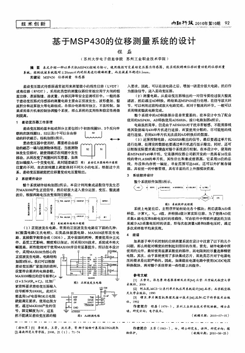
系统 上电复位后 ,主程 序开始初始 化各个模块 ;然后读取A D / 采 样值 ,计算V V 、d ,并根据 d 值 值计算实 际位移 。为了使得AD在
I
图2 系统 硬 件 结 构 示 意 图
( ) 1 正弦波发 生电路。常用的 正弦 波发生 电路有下面 的几种 :
3 系 统 软 件 设 计
整个 系统硬件结构如 图2 。本设计利用集 成函数信号发生芯 所示 片MA 08 x 3产生正弦信号 ,然后经放大送入差分运放 、变压 、整流 滤
波后 。根据两路电压改变得到位移值 。
_ l ^ l 咐 ” t t 啊 ^ ^
变 ! I
整个系统 软件如 图5 所示 。
南弘开 效 21 1期 9 o0 年第 0 2
一
基 于MSP 0 4 的位 移 测 量 系统 的设 计 3
程 磊
( 州 大 学 电子 信 息学 院 苏 州 工 业 职 业 技 术 学 院 ) 苏 摘 要 本文介绍一种 以单 片机Ms 4 O P 3 控制为核・ 心,使 用线性 可变差动 变压 器为传 感器,能实现较精确位移 测量功能的位移 测量
< >
。。 。。 。一
* . :I '
。。’。 f ’。。’’一 。 。。
—
— 一一
—!
。 。。。 。。。i。 。。。 一 。 ’
L—
‘ jt
§I
g :
’
L — _ L —— — j ——j — — —
囤5 系统 软 件 漉 程 图
动的杆状磁芯。结构如图 l 所示。 差动变压器 中使用时 ,需要将 自由移 动的磁芯 一端与被测物体相连 ,当被 测物
一种远距离大目标微位移测量系统设计

mie n ci db et nci r t s m ot tomoi rtem codslcm n o l g ud o o j t i t da dr e e yt a se e.I i i p r nt பைடு நூலகம் ir—i ae e t fa eotor be s n t e v h r v n a t o h p r c
Ze g Ha n o, Ya g S z o g, Ca ii n hih n o Haln
( ol efC m u i t nE gnei ,C ogigU i rt,C ogig4 0 3 , hn ) Clg o m n a o nier g hnqn n esy h nqn 00 0 C i e o ci n v i a
关 键词 :微 位移 ; 射 器 ; 发 系 统 反 收 中 图 分 类号 : P 7 T 24 文献 标 识 码 : A 国家 标 准 学科 分 类 代 码 : 6 .0 4 04
Ne mir-i lcme t au e n ytm rlreojc n i a c w cods ae n s rme t s p me s e f g bet nl gds n e o a i o t
Absr c :Th e s r m e ts se c nsss o e ev r。ta mitra e e tr T e wiee sm ir wa e I r n — ta t e m a u e n y tm o it fr c ie rns t nd rf co . h r l s c o v Sta s e l
无线电波信号 。在接收端 , 利用信号反射波相对于 发射信号 的相位 变化 , 以对 室外远距离 大型监测 目标 的微 小位移进 行测 可 量, 这种微位移测量系统可 以用 于山体滑坡和桥梁变形等监测 , 从而预 防 自然灾害发生 。本文 介绍 了微位移 测量 的基本原 理 , 同时给出了反射系统和收发系统设计方法。具体 系统 可以分为模拟和数字 2种不 同体制。
- 1、下载文档前请自行甄别文档内容的完整性,平台不提供额外的编辑、内容补充、找答案等附加服务。
- 2、"仅部分预览"的文档,不可在线预览部分如存在完整性等问题,可反馈申请退款(可完整预览的文档不适用该条件!)。
- 3、如文档侵犯您的权益,请联系客服反馈,我们会尽快为您处理(人工客服工作时间:9:00-18:30)。
摘要在现代工业生产过程中,常常需要测量很多不同的位移量。
与此同时对位移量进行较为精确地检测,是提高控制精度的基础。
因此之前所普遍采用的传统位移测量装置已经不能适应时代发展的潮流。
在此情况下通过科研人员的不断努力终于研制出了数字式光电编码器,它的输入量是角位移量其输出量是相应的电脉冲,并且它有体积小,精度高的优点。
故而,这次毕业设计选用的是光电编码器。
本次毕业设计是以AT89C51单片机为核心,用光电编码器来实现对位移量的精确测量,再将测量结果显示在LCD液晶显示器上。
其中本次设计中所选用的是输出电压为5V的光电编码器。
本文由浅入深先介绍了一些关于位移测量的基本原理,进而阐述了各个模块的设计思路,工作过程以及显示效果。
本文借鉴了一些当前较为流行的设计思想,例如硬件软件化,很好的满足了设计要求。
关键词:位移,测量,光电编码器,单片机,LCD显示器AbstractIn the control field, a variety of displacement measurements often need to be carried out. In actual industry position control domain, to increase the control precision, carries on the examination to the controlled member is accurately very important.The traditional machinery survey displacement installs has not been able to satisfy the modern production by far the need, but the digital sensor electro-optic encoder, can transform the angular displacement into with it correspondence electricity pulse output, mainly uses in the mechanical position and the velocity of whirl examination, has the precision to be high, volume small and so on characteristics, therefore this design decided that uses the electro-optical encoder to carry on the displacement to examine.This design to use the electro-optical encoder to realize the displacement survey and the simulation, realizes the survey from the exterior different displacement value and the demonstration. Makes concrete using at89C51 monolithic integrated circuit is the core, the electro-optical encoder carries on the displacement to survey, simultaneously by LCD liquid crystal display module demonstration. This design uses the electro-optical encoder output voltage is 5V, the output signal after four doubling circuit processing sends in the monolithic integrated circuit to carry on counting processing, finally sends in the LCD module demonstration.In this paper, detailed working process of displacement measurement system is started with principle of displacement measurement, and hardware circuit design and display. This paper has absorbed the idea of hardware and software to achieve with the subject required functionality.Key words:The displacement surveys, electro-optical encoder, microcontroller, LCD displaymodule目录第一章绪论·················································1.1位移测量及其传感器简介··································1.2光栅位移测量技术简介··································第二章原理及方案说明···································2.1 方案选择及原理··········································2.2位移测量参数及电路参数分析······························第三章系统电路的设计········································3.1 硬件电路的设计···········································3.1.1 单片机的选择·········································3.1.2 AT89C51的介绍········································3.1.3 1XP8001-1简介········································3.2 软件的设计···············································第四章显示部分···············································4.1 LCD显示器················································4.2 LCD分类及特点······································4.3 LCD1602液晶显示器································第五章仿真实现················································5.1 PROTEUS仿真软件简介·······································5.2 KEIL软件的简介··································结论······························································致谢······························································参考文献··························································第一章绪论1.1位移测量及其传感器简介位移包括线位移和角位移。