cisco交换机配置DHCP中继
交换机DHCP中继功能的配置
交换机DHCP 中继功能的配置一、 环境当DHCP 客户机和DHCP 服务器不在同一个网段时,由DHCP 中继传递DHCP 报文。
增加DHCP 中继功能的好处是不必为每个网段都设置DHCP 服务器,同一个DHCP 服务器可以为很多个子网的客户机提供网络配置参数,即节约了成本又方便了管理。
这就是DHCP 中继的功能。
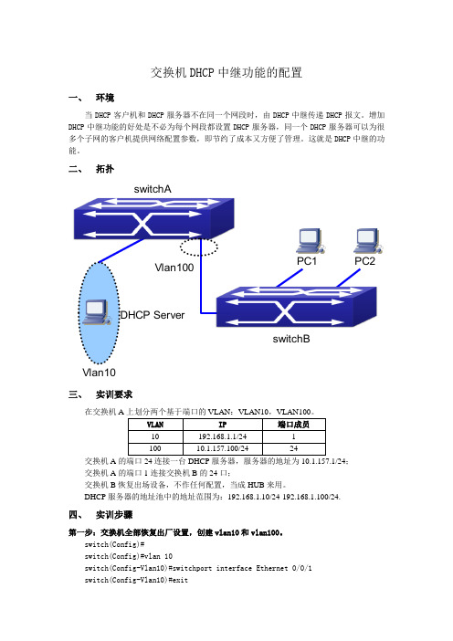
二、 拓扑switchA switchB Vlan10DHCP ServerVlan100PC2PC1 三、 实训要求在交换机A交换机A 的端口24连接一台DHCP 服务器,服务器的地址为10.1.157.1/24;交换机A 的端口1连接交换机B 的24口; 交换机B 恢复出场设备,不作任何配置,当成HUB 来用。
DHCP 服务器的地址池中的地址范围为:192.168.1.10/24-192.168.1.100/24.四、 实训步骤第一步:交换机全部恢复出厂设置,创建vlan10和vlan100。
switch(Config)#switch(Config)#vlan 10switch(Config-Vlan10)#switchport interface Ethernet 0/0/1switch(Config-Vlan10)#exitswitch(Config)#vlan 100switch(Config-Vlan100)#switchport interface Ethernet 0/0/24switch(Config-Vlan100)#exit第二步:给交换机设置IP地址。
switch(Config)#interface vlan 10switch(Config-If-Vlan10)#ip address 192.168.1.1 255.255.255.0 switch(Config-If-Vlan10)#no shutdownswitch(Config)#interface vlan 100switch(Config-If-Vlan100)#ip address 10.1.157.100 255.255.255.0 switch(Config-If-Vlan100)#no shutdown第三步:配置DHCP中继switch(Config)#service dhcpswitch(Config)#ip forward-protocol udp bootpsswitch(Config)#interface vlan 10switch(Config-If-Vlan10)#ip helper-address 10.1.157.1switch(Config-If-Vlan10)#exitswitch(Config)#第四步:验证实训。
交换机DHCP中继功能的配置
交换机DHCP中继功能的配置实验、交换机dhcp服务器的配置一、实验目的1、介绍dhcp原理;2、熟练掌握交换机作为dhcp服务器的配置方法;3、了解该功能的广泛应用。
二、应用环境大型网络一般都采用dhcp协议作为地址分配的方法,需要为网络购置多台dhcp服务器放置在网络的不同位置。
为减轻网络管理员和用户的配置负担,我们可以将支持dhcp 的交换机配置成dhcp服务器。
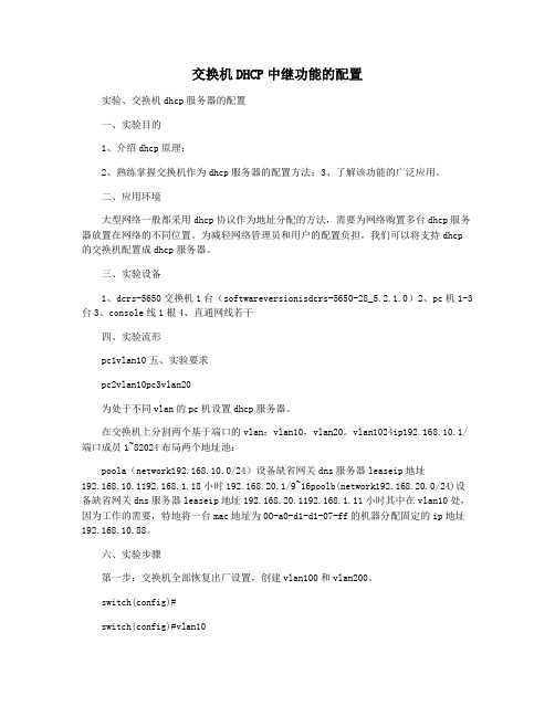
三、实验设备1、dcrs-5650交换机1台(softwareversionisdcrs-5650-28_5.2.1.0)2、pc机1-3台3、console线1根4、直通网线若干四、实验流形pc1vlan10五、实验要求pc2vlan10pc3vlan20为处于不同vlan的pc机设置dhcp服务器。
在交换机上分割两个基于端口的vlan:vlan10,vlan20。
vlan1024ip192.168.10.1/端口成员1~82024布局两个地址池:poola(network192.168.10.0/24)设备缺省网关dns服务器leaseip地址192.168.10.1192.168.1.18小时192.168.20.1/9~16poolb(network192.168.20.0/24)设备缺省网关dns服务器leaseip地址192.168.20.1192.168.1.11小时其中在vlan10处,因为工作的需要,特地将一台mac地址为00-a0-d1-d1-07-ff的机器分配固定的ip地址192.168.10.88。
六、实验步骤第一步:交换机全部恢复出厂设置,创建vlan100和vlan200。
switch(config)#switch(config)#vlan10switch(config-vlan10)#switchportinterfaceethernet0/0/1-8!给vlan10重新加入端口1-8settheportethernet0/0/1accessvlan100successfullysettheportethernet0/0/2accessv lan100successfullysettheportethernet0/0/3accessvlan100successfullysettheportet hernet0/0/4accessvlan100successfullysettheportethernet0/0/5accessvlan100succes sfullysettheportethernet0/0/6accessvlan100successfullysettheportethernet0/0/7a ccessvlan100successfullysettheportethernet0/0/8accessvlan100successfullyswitch (config-vlan10)#exitswitch(config)#vlan20switch(config-vlan20)#switchportinterfaceethernet0/0/9-16!给vlan20重新加入端口9-16settheportethernet0/0/9accessvlan200successfullysettheportethernet0/0/10access vlan200successfullysettheportethernet0/0/11accessvlan200successfullysettheport ethernet0/0/12accessvlan200successfullysettheportethernet0/0/13accessvlan200su ccessfullysettheportethernet0/0/14accessvlan200successfullysettheportethernet0 /0/15accessvlan200successfullysettheportethernet0/0/16accessvlan200successfull yswitch(config-vlan20)#exitswitch(config)#第二步:给交换机设置ip地址。
关于Cisco Packet Tracer DHCP中继配置实验的更新

关于Cisco Packet Tracer DHCP中继配置实验的更新2011-05-25 09:39早在2008年曾经介绍过Cisco Packet Tracer,这个思科的网络设备模拟软件,并用它根据CCNA教材内容做了一些模拟实验,近日有一网友说根据我的实验操作时DHCP中继实验没有成功。
(DHCP中继试验:《Packet Tracer 5.0建构CCNA实验攻略(16)——DHCP 中继配置》)我下面使得Cisco Packet Tracer5.3重新做DHCP中继的实验,尽量做得详细一些,供大家参考。
一、搭建实验环境添两个路由器与四个交换机及服务器、计算机。
为Router 1841添加所需要的模块,并为这个设备重新命名,然后连接这些设备。
在连接的时候要注意的就是两个路由器的串口相连时要知道哪一端是DTE,哪一端是DCE,是要为DCE上的串口配置clock rate参数。
图一在上图中,各个网络设备与计算机设备刚刚连接好,没有做任何配置。
在此时,计算机(服务器)交换机是互相连通的,但交换机与路由器,路由器之间的链路是不通的,所以路由器之间相连的端口,交换机与路由器之间相连的端口是红色的。
二、对设备做基本的配置1、配置路由器对路由器A的配置:Router>Router>enRouter#conf tEnter configuration commands, one per line. End with CNTL/Z.Router(config)#int fa0/1Router(config-if)#no shut \\激活FastEthernet0/1端口\\%LINK-5-CHANGED: Interface FastEthernet0/1, changed state to up%LINEPROTO-5-UPDOWN: Line protocol on Interface FastEthernet0/1, changed state to upRouter(config)#int fa0/0 \\激活FastEthernet0/0端口\\Router(config-if)#no shutRouter(config-if)#%LINK-5-CHANGED: Interface FastEthernet0/0, changed state to up%LINEPROTO-5-UPDOWN: Line protocol on Interface FastEthernet0/0, changed state to upRouter(config-if)#Router#Router(config)#int s0/1/0Router(config-if)#clock rate 56000 \\配置DCE端口的时钟频率\\ Router(config-if)#no shut \\激活serial0/1/0\\%LINK-5-CHANGED: Interface Serial0/1/0, changed state to downRouter(config-if)#对路由器B的配置:Router>enRouter#conf tEnter configuration commands, one per line. End with CNTL/Z.Router(config)#hostname RouterB \\为路由器B配置主机名\\RouterB(config)#int s0/1/0RouterB(config-if)#no shut \\激活serial0/1/0\\%LINK-5-CHANGED: Interface Serial0/1/0, changed state to upRouterB(config-if)#%LINEPROTO-5-UPDOWN: Line protocol on Interface Serial0/1/0, changed state to upRouterB(config-if)#int fa0/0RouterB(config-if)#no shut \\激活FastEthernet0/0端口\\RouterB(config-if)#%LINK-5-CHANGED: Interface FastEthernet0/0, changed state to up%LINEPROTO-5-UPDOWN: Line protocol on Interface FastEthernet0/0, changed state to upRouterB(config-if)#int fa0/1RouterB(config-if)#no shut \\激活FastEthernet0/1端口\\RouterB(config-if)#%LINK-5-CHANGED: Interface FastEthernet0/1, changed state to up%LINEPROTO-5-UPDOWN: Line protocol on Interface FastEthernet0/1, changed state to upRouterB(config-if)#图二通过以上的配置,模拟实验环境中的设备链路已经连通三、网络参数配置,实现网络设备互相连通可以访问1、配置三个服务器:DNS、DHCP和WWW。
使用路由器以及三层交换机配置DHCP中继
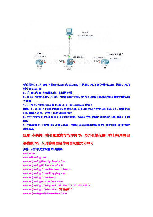
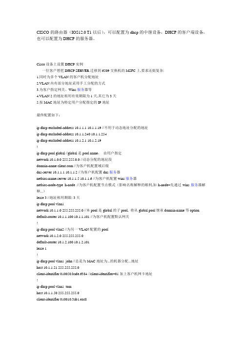
要求描述:1、在SW1上创建vlan10和vlan20,并将端口F0/3划分到vlan10,将端口F0/1划分到vlan 202、在SW1和R2上配置路由,是网络互通3、在R1上配置DHCP,在SW1上配置DHCP中继,使PC机能够自动获取到ip地址和默认网关地址4、在PC机上能够ping通R1和LO 0(即lookback接口)图解:1、在R2上F0/0上配置ip为192.168.0.2 LO0接口上配置192.168.1.1,配置完毕后配置默认路由,这样可以访问其他网段2、在三层交换机F0/2接口上开启路由功能,配地址并配置默认路由到达192.168.1.0的网段3、在路由器R1上配置地址和默认路由,这样可以达到其他的网段进行分配地址,配置DHCP 相关服务注意:本实例中所有配置命令均为简写,另外在模拟器中我们将用路由器模拟PC,只是将路由器的路由功能关闭即可步骤:我们首先来配置R2路由器router>enrouter#config terrouter(config)#no ip domain-loorouter(config)#line console 0router(config-line)#no exec-timeoutrouter(config-line)#logging synrouter(config-line)#exitrouter(config)#interface f0/0router(config-if)#ip add 192.168.0.2 25.255.255.0router(config-if)#no shut(开启接口)router(config-if)#interface lo 0router(config-if)#ip add 192.168.1.1 255.255.255.0router(config-if)#no shut(开启接口)router(config-if)#exitrouter(config)#ip route 0.0.0.0 0.0.0.0 192.168.0.1(默认路由,表示可以到达不同的网段)好了R2上面的路由器一斤配置完毕了,现在来开始配置三层交换机SW1>enSW1#config terSW1(config)#ip routingSW1(config)#no ip domain-looSW1(config)#line console 0SW1(config-line)#no exec-timeoutSW1(config-line)#logging synSW1(config-line)#exitSW1(config)#interface f0/2SW1(config-if)#no swtchportSW1(config-if)#ip add 192.168.0.1 255.255.255.0SW1(config-if)#no shutSW1(config)#ip route 0.0.0.0 0.0.0.0 192.168.0.2SW1(config-if)#endSW1#vlan data (创建vlan 10和vlan 20)SW1(vlan)#vlan 10SW1(vlan)#vlan 20SW1(vlan)#endSW1#config tSW1(config)#interface f0/1SW1(config-if)#swichport access vlan 20(将接口F0/1加入vlan 10)SW1(config)#interface f0/3SW1(config-if)#switchport access vlan 10(将接口F0/3加入vlan 10)SW1(config)#interface vlan 10SW1(config)#ip add 192.168.10.1 255.255.255.0(vlan 10的地址)SW1(config)#ip helper-add 192.168.20.1(配置中继,地址为DHCP服务器地址)SW1(config)#no shut(开启接口)SW1(config)#interface vlan 20SW1(config)#ip add 192.168.20.2 255.255.255.0(vlan 20的地址)SW1(config)#ip helper-add 192.168.20.1(配置中继,即DHCP服务器地址,也就是R1上面的地址)SW1(config)#no shut(开启接口)现在三层交换机配置完毕,现在开始配置路由器R1,即DHCP服务器router>enrouter#config terrouter(config)#no ip domain-loorouter(config)#line console 0router(config-line)#no exec-timeoutrouter(config-line)#logging synrouter(config-line)#exitrouter(config)#interface f0/0router(config-if)#ip add 192.168.20.1 255.255.255.0router(config-if)#no shutrouter(config-if)#exitrouter(config)#ip dhcp pool vlan10(给地址池命名为VLAN10,此处命名是可以随意的)router(dhcp-config)#network 192.168.10.0 255.255.255.0(给vlan 10要分配的网段)router(dhcp-config)#default-router 192.168.10.1(默认网关,为vlan 10 的地址)router(dhcp-config)#dns-server 202.103.46.148(要分配的DNS服务器地址)router(dhcp-config)#lease 2router(config)#ip dhcp excluded-address 192.168.10.1(预留的IP地址,即vlan 10的静态地址,表示不分配出去)router(config)#ip route 0.0.0.0 0.0.0.0 192.168.20.2(默认路由,表示可以到达不同的网段)前面我刚讲过我们是在模拟器中我们将用路由器模拟PC,所以我们还要对此PC进行相关配置,不过真机情况下就不需要对此PC做任何配置router>enrouter#config terrouter(config)#no ip domain-loorouter(config)#hostname pcpc(config)#line console 0pc(config-line)#no exec-timeoutpc(config-line)#logging synpc(config-line)#exitpc(config)#interface f0/0pc(config-if)#no shut (开启接口)pc(config)#no ip routing(表示关闭路由功能)pc(config)#ip add dhcp (表示从DHCP上获得地址)。
cisco DHCP
CISCO的路由器(IOS12.0 T1以后),可以配置为dhcp的中继设备,DHCP的客户端设备,也可以配置为DHCP的服务器。
Cisco设备上设置DHCP实例一位客户想把DHCP SERVER迁移到6509交换机的MSFC上,要求还挺复杂:1.同时为多个VLAN的客户机分配地址2.VLAN内有部分地址采用手工分配的方式3.为客户指定网关、Wins服务器等4.VLAN 2的地址租用有效期限为1天,其它为3天5.按MAC地址为特定用户分配指定的IP地址最终配置如下:ip dhcp excluded-address 10.1.1.1 10.1.1.19 //不用于动态地址分配的地址ip dhcp excluded-address 10.1.1.240 10.1.1.254ip dhcp excluded-address 10.1.2.1 10.1.2.19!ip dhcp pool global //global是pool name,由用户指定network 10.1.0.0 255.255.0.0 //动态分配的地址段domain-name //为客户机配置域后缀dns-server 10.1.1.1 10.1.1.2 //为客户机配置dns服务器netbios-name-server 10.1.1.5 10.1.1.6 //为客户机配置wins服务器netbios-node-type h-node //为客户机配置节点模式(影响名称解释的顺利,如h-node=先通过wins服务器解释...)lease 3 //地址租用期限: 3天ip dhcp pool vlan1network 10.1.1.0 255.255.255.0 //本pool是global的子pool, 将从global pool继承domain-name等option default-router 10.1.1.100 10.1.1.101 //为客户机配置默认网关!ip dhcp pool vlan2 //为另一VLAN配置的poolnetwork 10.1.2.0 255.255.255.0default-router 10.1.2.100 10.1.2.101lease 1!ip dhcp pool vlan1_john //总是为MAC地址为...的机器分配...地址host 10.1.1.21 255.255.255.0client-identifier 010050.bade.6384 //client-identifier=01加上客户机网卡地址!ip dhcp pool vlan1_tomhost 10.1.1.50 255.255.255.0client-identifier 010010.3ab1.eac8相关的DHCP调试命令:no service dhcp //停止DHCP服务[默认为启用DHCP服务]sh ip dhcp binding //显示地址分配情况show ip dhcp conflict //显示地址冲突情况debug ip dhcp server {events | packets | linkage} //观察DHCP服务器工作情况如果DHCP客户机分配不到IP地址,常见的原因有两个。
思科模拟器——DHCP服务器中继实验
思科模拟器——DHCP服务器中继实验2017-7-9基于思科模拟器ZKY正品体育思科模拟器DHCP服务器中继实验【DHCP服务器中继案例1】只有⼀个⽹段的DHCP中继其中路由器作为DHCP服务器,交换机作为中继⼀、交换机配置过程Switch>Switch>enSwitch#confSwitch(config)#vlan 10 创建VLAN 10Switch(config-vlan)#exitSwitch(config)#int vlan 10Switch(config-if)#ip address 192.168.10.254 255.255.255.0 为VLAN 10配置地址Switch(config-if)#no shut 开启虚拟接⼝Switch(config-if)#exitSwitch(config)#int fa0/1Switch(config-if)#switchport access vlan 10 将fa0/1加⼊vlan 10Switch(config-if)#exitSwitch(config)#int fa0/24Switch(config-if)#no switchport 将交换⼝转换为路由⼝Switch(config-if)#ip adSwitch(config-if)#ip address 172.16.1.1 255.255.255.0Switch(config-if)#no shutSwitch(config-if)#exSwitch(config)#ip route 0.0.0.0 0.0.0.0 172.16.1.2Switch(config-if)#Switch(config-if)#exitSwitch(config)#int vlan 10Switch(config-if)#ip ?access-group Specify access control for packetsaddress Set the IP address of an interfacehello-interval Configures IP-EIGRP hello intervalhelper-address Specify a destination address for UDP broadcasts nat NAT interface commandsospf OSPF interface commandsproxy-arp Enable proxy ARPsplit-horizon Perform split horizonsummary-address Perform address summarizationSwitch(config-if)#ip helpSwitch(config-if)#ip helper-address 172.16.1.2Switch(config-if)#endSwitch#%SYS-5-CONFIG_I: Configured from console by consoleSwitch#sh ip routeCodes: C - connected, S - static, I - IGRP, R - RIP, M - mobile, B - BGPD - EIGRP, EX - EIGRP external, O - OSPF, IA - OSPF inter areaN1 - OSPF NSSA external type 1, N2 - OSPF NSSA external type 2E1 - OSPF external type 1, E2 - OSPF external type 2, E - EGPi - IS-IS, L1 - IS-IS level-1, L2 - IS-IS level-2, ia - IS-IS inter area* - candidate default, U - per-user static route, o - ODRP - periodic downloaded static routeGateway of last resort is 172.16.1.2 to network 0.0.0.0172.16.0.0/24 is subnetted, 1 subnetsC 172.16.1.0 is directly connected, FastEthernet0/24C 192.168.10.0/24 is directly connected, Vlan10S* 0.0.0.0/0 [1/0] via 172.16.1.2Switch#confConfiguring from terminal, memory, or network [terminal]?Enter configuration commands, one per line. End with CNTL/Z. Switch(config)#ip routingSwitch(config)#endSwitch#%SYS-5-CONFIG_I: Configured from console by consoleSwitch#wrBuilding configuration...⼆、路由器配置过程Router>enRouter#confRouter(config)#int f0/0Router(config-if)#ip address 172.16.1.2 255.255.255.0Router(config-if)#exitRouter(config)#ip dhcp ?excluded-address Prevent DHCP from assigning certain addressespool Configure DHCP address poolsRouter(config)#ip dhcp excluded-address 192.168.10.254 排除地址,避免客户端获得此IP地址产⽣冲突Router(config)#ip dhcp pool vlan10 (创建地址池vlan10)Router(dhcp-config)#? (通过?可以知道DHCP服务器可以配置哪些选项)default-router Default routersdns-server Set name serverexit Exit from DHCP pool configuration modenetwork Network number and maskno Negate a command or set its defaultsoption Raw DHCP optionsRouter(dhcp-config)#default-router 192.168.10.254 (为客户端配置默认⽹关)Router(dhcp-config)#dns-server 192.168.10.254 (为客户端配置DNS)Router(dhcp-config)#netRouter(dhcp-config)#network 192.168.10.0 255.255.255.0 (客户端所在⽹络及掩码)Router(dhcp-config)#end Router(config)#ip route 0.0.0.0 0.0.0.0 172.16.1.1Router(config)#int fa0/0Router(config-if)#no shut【DHCP服务器中继案例2】有多个⽹段的DHCP中继⼀、交换机配置过程Switch>enSwitch#conf tEnter configuration commands, one per line. End with CNTL/Z.1.创建vlan 10,vlan20,vlan 30Switch(config)#vlan 10Switch(config-vlan)#vlan 20Switch(config-vlan)#vlan 30Switch(config-vlan)#2.为3个vlan创建相应的IP地址,并在vlan中创建中继,指向DHCP服务器地址Switch(config)#interface vlan 10Switch(config-if)#ip address 192.168.10.254 255.255.255.0Switch(config-if)#ip helper-address 172.16.1.2Switch(config)#interface vlan 20Switch(config-if)#ip address 192.168.20.254 255.255.255.0Switch(config-if)#ip helper-address 172.16.1.2Switch(config-if)#exitSwitch(config)#interface vlan 30Switch(config-if)#ip address 10.0.0.1 255.0.0.0Switch(config-if)#ip helper-address 172.16.1.23.将fa0/1,fa0/11,fa0/21分别加⼊vlan 10,vlan 20,vlan 30 Switch(config)#interface fastEthernet 0/1Switch(config-if)#switchport access vlan 10Switch(config)#interface fastEthernet 0/11Switch(config-if)#switchport access vlan 20Switch(config-if)#exitSwitch(config)#interface fastEthernet 0/21Switch(config-if)#switchport access vlan 30Switch(config-if)#Switch(config-if)#4.将fa0/24设置为路由⼝,并设置IP地址Switch(config)#interface fastEthernet 0/24Switch(config-if)#no switchportSwitch(config-if)#ip address 172.16.1.1 255.255.255.252 Switch(config-if)#5.设置默认路由,指向下⼀跳地址(即路由器接⼝地址)Switch(config-if)#exitSwitch(config)#ip route 0.0.0.0 0.0.0.0 172.16.1.2Switch(config)#6.交换机开启路由功能(总是会忘记这个,忘记了N次了)Switch(config)#ip routing7.保存配置Switch(config)#exitSwitch#%SYS-5-CONFIG_I: Configured from console by console Switch#wrBuilding configuration...[OK]Switch#⼆、路由器配置过程1.为路由器接⼝fa0/0配置IP地址,并开启接⼝Router>enRouter#conf tRouter(config)#interface fastEthernet 0/0Router(config-if)#ip address 172.16.1.2 255.255.255.252Router(config-if)#no shutdown (路由器默认情况下端⼝是禁⽤的,所以要开启,⽽交换机默认情况下端⼝是开启的,所以不需要敲此条命令)Router(config-if)#2.添加排除地址,避免客户端获得如下地址,产⽣IP地址冲突。
Cisco三层交换机与Routeros OSPF+DHCP服务器配置实例
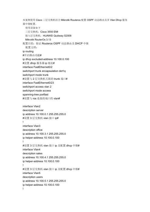
本案例使用Cisco三层交换机结合Mikrotik Routeros配置OSPF动态路由及多Vlan Dhcp服务器中继配置。
使用设备如下三层交换机:Cisco 3550 EMI接入层交换机:HUAWEI Quidway S2008Mikrotik RouterOs 3.13配置目的:验证Routeros OSPF动态路由及DHCP中继配置文档:ip routing#开启路由功能#ip dhcp excluded-address 10.100.0.100#设置dhcp服务器ip地址#interface FastEthernet0/2switchport trunk encapsulation dot1qswitchport mode trunk#设置与2层交换机互联的trunk端口#interface FastEthernet0/23switchport access vlan 2switchport mode accessspanning-tree portfast#设置与ros连接的端口的vlan#interface Vlan2description serverip address 10.100.0.1 255.255.255.0#设置3层交换机vlan接口ip#!interface Vlan3description officeip address 10.100.3.1 255.255.255.0ip helper-address 10.100.0.100!#设置3层交换机vlan接口ip及配置dhcp中继#interface Vlan4description salesip address 10.100.4.1 255.255.255.0ip helper-address 10.100.0.100!#设置3层交换机vlan接口ip及配置dhcp中继#interface Vlan5description usersip address 10.100.5.1 255.255.255.0ip helper-address 10.100.0.100!#设置3层交换机vlan接口ip及配置dhcp中继#router ospf 10router-id 10.100.0.1log-adjacency-changesnetwork 10.100.0.0 0.0.255.255 area 10.100.0.0#配置ospf进程及area信息#HUAWEI Quidway S2008 配置:interface Ethernet0/6switchport access vlan 5!#配置用户端口#interface Ethernet0/7switchport access vlan 3!#配置用户端口#interface Ethernet0/8switchport access vlan 4#配置用户端口#interface Ethernet0/9switchport mode trunkswitchport trunk allowed vlan all!#设置与3层交换机互联的trunk端口#Mikrotik Routeros:/ip pooladd name="vlan3" ranges=10.100.3.2-10.100.3.254add name="vlan4" ranges=10.100.4.2-10.100.4.254add name="vlan5" ranges=10.100.5.2-10.100.5.254#设置不同Vlan的地址池#/ip dhcp-serveradd address-pool=vlan3 authoritative=after-2sec-delay bootp-support=static \ disabled=no interface=in lease-time=3d name="vlan3" relay=10.100.3.1 add address-pool=vlan4 authoritative=after-2sec-delay bootp-support=static \ disabled=no interface=in lease-time=3d name="vlan4" relay=10.100.4.1 add address-pool=vlan5 authoritative=after-2sec-delay bootp-support=static \ disabled=no interface=in lease-time=3d name="vlan5" relay=10.100.5.1#设置Dhcp-server 使之支持Dhcp中继#/routing ospf areaadd area-id=0.0.0.0 authentication=none disabled=no name="backbone" \type=defaultadd area-id=10.100.0.0 authentication=none disabled=no name="area1" \type=default#配置ospf area#/ip addressadd address=10.100.0.100/24 broadcast=10.100.0.255 comment="" disabled=no \ interface=in network=10.100.0.0#配置内部IP地址#/ip dnsset allow-remote-requests=yes cache-max-ttl=1w cache-size=2048KiB \max-udp-packet-size=512 primary-dns=192.168.100.208 \#配置dns#/ip firewall natadd action=masquerade chain=srcnat comment="" disabled=no \src-address=10.100.0.0/16#配置NAT#/routing ospfset distribute-default=always-as-type-2 metric-bgp=20 metric-connected=20 \metric-default=1 metric-rip=20 metric-static=20 mpls-te-area=unspecified \mpls-te-router-id=unspecified redistribute-bgp=no \redistribute-connected=no redistribute-rip=no redistribute-static=no \router-id=10.100.100.2/routing ospf interfaceadd authentication=none authentication-key="" cost=10 dead-interval=40s \disabled=no hello-interval=10s interface=in network-type=broadcast \passive=no priority=1 retransmit-interval=5s transmit-delay=1s/routing ospf networkadd area=area1 disabled=no network=10.100.0.0/16#配置OSPF路由协议#cisco3550#show ip routeCodes: C - connected, S - static, R - RIP, M - mobile, B - BGPD - EIGRP, EX - EIGRP external, O - OSPF, IA - OSPF inter areaN1 - OSPF NSSA external type 1, N2 - OSPF NSSA external type 2E1 - OSPF external type 1, E2 - OSPF external type 2, E - EGPi - IS-IS, su - IS-IS summary, L1 - IS-IS level-1, L2 - IS-IS level-2ia - IS-IS inter area, * - candidate default, U - per-user static routeo - ODR, P - periodic downloaded static routeGateway of last resort is 10.100.0.100 to network 0.0.0.010.0.0.0/24 is subnetted, 4 subnetsC 10.100.4.0 is directly connected, Vlan4C 10.100.5.0 is directly connected, Vlan5C 10.100.3.0 is directly connected, Vlan3C 10.100.0.0 is directly connected, Vlan2O*E2 0.0.0.0/0 [110/1] via 10.100.0.100, 01:09:52, Vlan2[admin@MikroTik] /ip route> printFlags: X - disabled, A - active, D - dynamic, C - connect, S - static, r - rip, b - bgp, o - ospf, m - mme, B - blackhole, U - unreachable, P - prohibit# DST-ADDRESS PREF-SRC GATEWAY-STATEGATEWAY DISTANCE INTERFACEADS 0.0.0.0/0 reachable 192.168.18.1 0 o ut1ADC 10.100.0.0/24 10.100.0.100 0 in2ADo 10.100.3.0/24 reachable 10.100.0.1 110 in3ADo 10.100.4.0/24 reachable 10.100.0.1 110 in4ADo 10.100.5.0/24 reachable 10.100.0.1 110 in5ADC 192.168.18.0/24 192.168.18.158 0 out。
cisco_3560配置手册
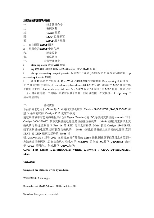
三层交换机配置与管理一、曰常管理命令二、密码恢复三、VLAN配置四、SPAN监听配置五、DHCP服务配置1. 在上配置DHCP服务2. 配置作为DHCP中继代理六、流量控制七、策略路由一、曰常管理命令l clear arp-cache清除ARP缓存l arp 192.168.100.22 000a.eb22.c1b5 arpa 绑定MAC和IPl sh ip accounting output-packets显示统计信息(当然需要配置统计功能如:ip accounting-transits 3200)l 通过IP追查交换机端口:CiscoWorks 2000 LMS网管软件的User tracking可以追查一个IP地址对应的端口。
sh mac-address-table address 00e0.9102.afd0 显示这个MAC地址在哪个接口出来的;sh mac-address-table interface Fa0/20显示20端口上的MAC地址,如果只有一个,则可能连接一个电脑,如果有很多个条目,则可以连接一个交换机。
sh cdp entry *显示邻居信息;二、密码恢复下面步骤也适用于Cisco 层 2 系列的交换机比如Catalyst 2900/3500XL,2940,2950/2955和层3 系列的比如Catalyst 3550 的密码恢复.通过终端或带有仿真终端程序(比如Hyper Terminal)的PC,连接到交换机的console 对于Catalyst 2900/3500XL 拔下交换机的电源线,然后按住交换机的Mode 按钮,再重新插上交换机的电源线.直到端口Port 1x 的LED 熄灭之后释放Mode 按钮.Catalyst 2940/2950L 拔下交换机的电源线,然后按住交换机的Mode 按钮,再重新插上交换机的电源线.直到STAT 的LED 熄灭之后释放Mode 按钮. Catalyst 2955 对于2955 交换机,它没有外部的Mode 按钮,因此就不能使用之前的那种方法来进行密码恢复.在交换机启动时,对于Windows 系列的PC,按下Ctrl+Break 键;对于UNIX 系列的工作站,按下Ctrl+C.如下:C2955 Boot Loader (C2955HBOOTM) Version 12.1(0.0.514), CISCO DEVELOPMENT TESTVERSIONCompiled Fri 13Dec02 17:38 by madisonWSC2955T12 starting...Base ethernet MAC Address: 00:0b:be:b6:ee:00Xmodem file system is available.Initializing Flash...flashfs[0]: 19 files, 2 directoriesflashfs[0]: 0 orphaned files, 0 orphaned directories flashfs[0]: Total bytes: 7741440flashfs[0]: Bytes used: 4510720 flashfs[0]: Bytes available: 3230720 flashfs[0]: flashfsfsck took 7 seconds....done initializing flash.Boot Sector Filesystem (bs:) installed, fsid: 3Parameter Block Filesystem (pb:) installed, fsid: 4/---接下来交换机会在15 秒内自动启动,等出现该信息之后,按下Ctrl+Break 键或Ctrl+C 键----/The system has been interrupted prior to initializing the flash file system to finishloading the operating system software:flash_init load_helper bootswitch:接下来输入flash_init 命令: switch: flash_init Initializing Flash...flashfs[0]: 143 files, 4 directoriesflashfs[0]: 0 orphaned files, 0 orphaned directories flashfs[0]: Total bytes: 3612672flashfs[0]: Bytes used: 2729472 flashfs[0]: Bytes available: 883200 flashfs[0]: flashfs fsck took 86 seconds....done Initializing Flash.Boot Sector Filesystem (bs:) installed, fsid: 3Parameter Block Filesystem (pb:) installed, fsid: 4switch:接着输入load_helper 命令: switch: load_helper switch:再输入dir flash:命令显示交换机的文件系统:switch: dir flash: Directory of flash:/2 rwx 1803357 <date> c3500xlc3h2smz.1205.WC7.bin4 rwx 1131 <date> config.text5 rwx 109 <date> info6 rwx 389 <date> env_vars7 drwx 640 <date> html18 rwx 109 <date> info.ver403968 bytes available (3208704 bytes used)switch:把配置文件重命名:switch: rename flash:config.text flash:config.old switch:输入boot 命令启动交换机:switch: bootLoading"flash:c3500xlc3h2smz.1205.WC7.bin"...#################### #################################File "flash:c3500xlc3h2smz.1205.WC7.bin" uncompressed and installed, entry point: 0x3000executing...(略)不进入setup 模式:System Configuration DialogAt any point you may enter a question mark '?' for help. Use ctrlc to abort configuration dialog at any prompt. Default settings are in square brackets '[]'.Continue with configuration dialog? [yes/no]: n进入特权模式,恢复原始的配置文件:Switch#rename flash:config.old flash:config.textDestination filename [config.text] Switch#把配置文件保存在内存里:Switch#copy flash:config.text system:runningconfigDestination filename [runningconfig]?1131 bytes copied in 0.760 secsSwitch# 进入全局配置模式,取消密码设置: Switch(config)#no enable secret 保存配置: Switch#write memoryBuilding configuration...[OK] Switch#三、VLAN配置我们现在是一个具备三层交换功能的核心交换机接几台分支交换机(不具备三层交换能力)。
- 1、下载文档前请自行甄别文档内容的完整性,平台不提供额外的编辑、内容补充、找答案等附加服务。
- 2、"仅部分预览"的文档,不可在线预览部分如存在完整性等问题,可反馈申请退款(可完整预览的文档不适用该条件!)。
- 3、如文档侵犯您的权益,请联系客服反馈,我们会尽快为您处理(人工客服工作时间:9:00-18:30)。
cisco交换机配置DHCP
Cisco 3550配置dhcp,网络上多有讨论,但大都存在错漏,按照网上介绍的配置一句“IP HELPER-ADDRESS DHCP服务器地址”后,工程当中发现客户机不能从DHCP服务器获取IP地址,本人最近也刚好配置了3550作为DHCP服务器中继代理,最初也曾困惑很久,后来在网上查找资料及在论坛上寻求众人帮助,终于在工程当中测试通过,为避免大家在工程当中遇到此类情况左调右调,特将配置过程写出来,给大家作为参考。
网络环境:一台3550EMI交换机,划分三个vlan,vlan2 为服务器所在网络,命名为server,IP 地址段为192.168.2.0,子网掩码:255.255.255.0,网关:192.168.2.1,域服务器为windows 2000 advance server,同时兼作DHCP服务器,DNS服务器,IP地址为192.168.2.10,vlan3为客户机1所在网络,IP地址段为192.168.3.0,子网掩码:255.255.255.0,网关:192.168.3.1命名为work01,vlan4 为客户机2所在网络,命名为work02,IP地址段为192.168.4.0,子网掩码:255.255.255.0,网关:192.168.4.1.
3550上端口1-8划到VLAN 2,端口9-16划分到VLAN 3,端口17-24划分到VLAN 4.
配置命令及步骤如下:
第一步:创建VLAN
Switch>Vlan Database
Switch(Vlan)>Vlan 2 Name server
Switch(Vlan)>Vlan 3 Name work01
Switch(vlan)>Vlan 4 Name work02
第二步:启用DHCP中继代理
/*在VLAN中使用“IP HELPER-ADDRESS DHCP服务器地址”指定DHCP服务器*/
Switch>Enable
Switch#Config t
Switch(Config)#Service Dhcp
Switch(Config)#Ip Dhcp Relay Information Option
第三步:设置VLAN IP地址
Switch(Config)#Int Vlan 2
Switch(Config-vlan)#Ip Address 192.168.2.1 255.255.255.0
Switch(Config-vlan)#No Shut
Switch(Config-vlan)#Int Vlan 3
Switch(Config-vlan)#Ip Address 192.168.3.1 255.255.255.0
Switch(Config-vlan)#No Shut
Switch(Config-vlan)#Int Vlan 4
Switch(Config-vlan)#Ip Address 192.168.4.1 255.255.255.0
Switch(Config-vlan)#No Shut
Switch(Config-vlan)#Exit
/*注意:由于此时没有将端口分配置到VLAN2,3,4,所以各VLAN会DOWN掉,待将端口分配到各VLAN后,VLAN会起来*/
第四步:设置端口全局参数
Switch(Config)#Interface Range Fa 0/1 - 24
Switch(Config-if-range)#Switchport Mode Access
Switch(Config-if-range)#Spanning-tree Portfast
第五步:将端口添加到VLAN2,3,4中
/*将端口1-8添加到VLAN 2*/
Switch(Config)#Interface Range Fa 0/1 - 8
Switch(Config-if-range)#Switchport Access Vlan 2
/*将端口9-16添加到VLAN 3*/
Switch(Config)#Interface Range Fa 0/9 - 16
Switch(Config-if-range)#Switchport Access Vlan 3
/*将端口17-24添加到VLAN 4*/
Switch(Config)#Interface Range Fa 0/17 - 24
Switch(Config-if-range)#Switchport Access Vlan 4
Switch(Config-if-range)#Exit
/*经过这一步后,各VLAN会起来*/
第六步:在VLAN3和4中设定DHCP服务器地址
/*VLAN 2中不须指定DHCP服务器地址*/
Switch(Config)#Int Vlan 3
Switch(Config-vlan)#Ip Helper-address 192.168.2.10
Switch(Config)#Int Vlan 4
Switch(Config-vlan)#Ip Helper-address 192.168.2.10
第七步:启用路由
/*路由启用后,各VLAN间主机可互相访问,若需进一步控制访问权限,则需应用到访问控制列表*/
Switch(Config)#Ip Routing
第八步:结束并保存配置
Switch(Config-vlan)#End
Switch#Copy Run Start。