格力R410A多联机
格力多联机GMV内机(R410A)H系列
连接管
气管
mm
Φ9.52
Φ9.52
Φ12.7
Φ12.7
Φ12.7
液管
mm
Φ6.35
Φ6.35
Φ6.35
Φ6.35
Φ6.35
连接方式
喇叭口连接
排水管(外径×壁厚)
mm
Φ20×1.5
Φ30×1.5
尺寸
(宽×深×高)
mm
875×680×220
980×736×266
净重
kg
27
36
注:a. 本机组设计执行标准GB/T18837-2002。
GMV-R28P/Na; GMVL-R28P/Na GMV-R32P/Na; GMVL-R32P/Na
GMV-R36P/Na; GMVL-R36P/Na GMV-R40P/Na; GMVL-R40P/Na
GMV-R45P/Na; GMVL-R45P/Na GMV-R50P/Na; GMVL-R50P/Na
GMV-R56P/Na; GMVL-R56P/Na GMV-R63P/Na; GMVL-R63P/Na
GMV-R71P/Na; GMVL-R71P/Na GMV-R80P/Na; GMVL-R80P/Na
GMV-R90P/NaS; GMVL-R90P/NaGMV-R100P/NaS;GMVL-R100P/Na
室内机普通静压配置,符合家居环境的要求,能将凉爽/温暖均匀送至室内的每一处空间,风量小,噪音低。四档风机配置,可根据实际的工程需要调整室内机的静压及风量,有效的解决了风声和风量的冲突问题。
◆ 灵活设置,均匀送风
风管可根据用户需要灵活配置,在一个或多个房间里设置多个回风口和送风口,有效解决大面积居室或多个房间同时供应冷量或热量以及均匀送风的需要。
R410A分离式空调系列用户手册说明书
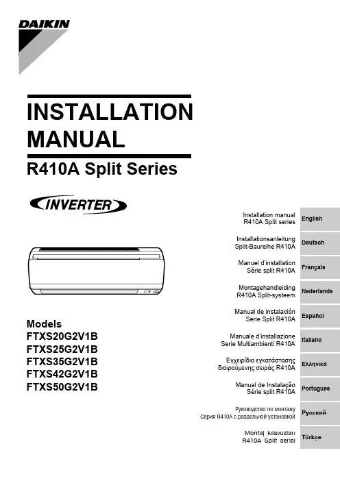
INSTALLATION MANUALR410A Split SeriesModelsFTXS20G2V1B FTXS25G2V1B FTXS35G2V1B FTXS42G2V1BFTXS50G2V1BDeutschFrançaisNederlandsEspañolItalianoΕλληνικÜPortuguesРóссêийEnglishTürkçeInstallation manual R410A Split series Montaj kýlavuzlarý R410A Split serisiInstallationsanleitung Split-Baureihe R410A Manuel d’installation Série split R410A Montagehandleiding R410A Split-systeem Manual de instalaciónSerie Split R410A Manuale d’installazione Serie Multiambienti R410A Εγχειρßδιο εγκατÜστασηòδιαιροýìενηò σειρÜò R410AManual de Instalação Série split R410AРóêоводство по монтажóСерия R410A с раздельной óстановêойU m e d a C e n t e r B l d g ., 2-4-12, N a k a z a k i -N i s h i ,K i t a -k u , O s a k a , 530-8323 J a p a n0G 2V 1B , F T X S 25G 2V 1B , F T X S 35G 2V 1B , F T X S 42G 2V 1B , F T X S 50G 2V 1BI N I N D U S T R I E S , L T D .S h i n r i S a d a M a n a g e r Q u a l i t y C o n t r o l D e p a r t m e n t 1s t . o f N o v . 2008L o w V o l t a g e 2006/95/E C E l e c t r o m a g n e t i c C o m p a t i b i l i t y 2004/108/E C *D A I K I N .T C F .015 L 3/08-2007K E M A Q u a l i t y B .V .74736-K R Q /E M C 97-4957Safety Precautions•The precautions described herein are classified as WARNING and CAUTION. They both contain important informa-tion regarding safety. Be sure to observe all precautions without fail.•Meaning of WARNING and CAUTION noticesWARNING....Failure to follow these instructions properly may result in personal injury or loss of life.CAUTION.....Failure to observe these instructions properly may result in property damage or personal injury, which may be serious depending on the circumstances.•The safety marks shown in this manual have the following meanings:Be sure to follow the instructions. Be sure to establish an earth connection. Never attempt.•After completing installation, conduct a trial operation to check for faults and explain to the customer how to operate the air conditioner and take care of it with the aid of the operation manual.WARNING•Ask your dealer or qualified personnel to carry out installation work.Do not attempt to install the air conditioner yourself. Improper installation may result in water leakage, electric shocks or fire.•Install the air conditioner in accordance with the instructions in this installation manual.Improper installation may result in water leakage, electric shocks or fire.•Be sure to use only the specified accessories and parts for installation work.Failure to use the specified parts may result in the unit falling, water leakage, electric shocks or fire.•Install the air conditioner on a foundation strong enough to withstand the weight of the unit.A foundation of insufficient strength may result in the equipment falling and causing injury.•Electrical work must be performed in accordance with relevant local and national regulations and with instructions in this installation manual. Be sure to use a dedicated power supply circuit only.Insufficiency of power circuit capacity and improper workmanship may result in electric shocks or fire.•Use a cable of suitable length.Do not use tapped wires or an extension lead, as this may cause overheating, electric shocks or fire.•Make sure that all wiring is secured, the specified wires are used, and that there is no strain on the terminal con-nections or wires.Improper connections or securing of wires may result in abnormal heat build-up or fire.•When wiring the power supply and connecting the wiring between the indoor and outdoor units, position the wires so that the control box lid can be securely fastened.Improper positioning of the control box lid may result in electric shocks, fire or over heating terminals.•If refrigerant gas leaks during installation, ventilate the area immediately.Toxic gas may be produced if the refrigerant comes into contact with fire.•After completing installation, check for refrigerant gas leakage. Toxic gas may be produced if the refrigerant gas leaks into the room and comes into contact with a source of fire, such as a fan heater, stove or cooker.•When installing or relocating the air conditioner, be sure to bleed the refrigerant circuit to ensure it is free of air, and use only the specified refrigerant (R410A).The presence of air or other foreign matter in the refrigerant circuit causes abnormal pressure rise, which may result in equipment damage and even injury.•During installation, attach the refrigerant piping securely before running the compressor.If the compressor is not attached and the stop valve is open when the compressor is run, air will be sucked in, causing abnormal pressure in the refrigeration cycle, which may result in equipment damage and even injury.•During pump-down, stop the compressor before removing the refrigerant piping.If the compressor is still running and the stop valve is open during pump-down, air will be sucked in when the refrigerant piping is removed, causing abnormal pressure in the refrigeration cycle, which may result in equipment damage and even injury.•Be sure to earth the air conditioner. Do not earth the unit to a utility pipe, lightning conductor or telephone earth lead.Imperfect earthing may result in electric shocks.•Be sure to install an earth leakage breaker.Failure to install an earth leakage breaker may result in electric shocks or fire.CAUTION•Do not install the air conditioner at any place where there is a danger of flammable gas leakage.In the event of a gas leakage, build-up of gas near the air conditioner may cause a fire to break out.•While following the instructions in this installation manual, install drain piping to ensure proper drainage and insu-late piping to prevent condensation.Improper drain piping may result in indoor water leakage and property damage.•Tighten the flare nut according to the specified method such as with a torque wrench.If the flare nut is too tight, it may crack after prolonged use, causing refrigerant leakage.AccessoriesChoosing an Installation Site•Before choosing the installation site, obtain user approval.1.Indoor unit.•The indoor unit should be sited in a place where:1)the restrictions on installation specified in the indoor unit installation drawings are met,2)both air intake and exhaust have clear paths met,3)the unit is not in the path of direct sunlight,4)the unit is away from the source of heat or steam,5)there is no source of machine oil vapour (this may shorten indoor unit life),6)cool (warm) air is circulated throughout the room,7)the unit is away from electronic ignition type fluorescent lamps (inverter or rapid start type) as they may shorten the remote controller range,8)the unit is at least 1 metre away from any television or radio set (unit may cause interference with the picture or sound),9)install at the recommended height (1.8m).2.Wireless remote controller.1)Turn on all the fluorescent lamps in the room, if any, and find the site where remote controller signals are properly received by the indoor unit (within 7 metres).2)Make the dipswitch settings. Set according to the type of unit purchased by the customer. The default settings are on the heat pump side.•For cooling only (Outdoor unit model: RKS)Set the dipswitches on the cooling only side.•For heat pump (Outdoor unit model: RXS)Check that the dipswitches are on the heat pump side.If they are set on the cooling only side, move them to the heat pump side.Installation Tips1.Removing and installing front panel.•Removal methodHook fingers on the panel protrusions on the left and right of the main body, and open until the panel stops. Slide the front panel sideways to disengage the rotating shaft. Then pull the front panel toward you to remove it.•Installation method2.Removing and installing front grille.•Removal method1)Remove front panel to remove the air filter.2)Remove the front grille.3)In front of the {{{of your other hand.When there is no work space because the unit is close to ceilingCAUTIONBe sure to wear protection gloves.Place both hands under the center of the front grille, and while pushing up, pull it toward you.•Installation method1)Install the front grille and firmly engage the upper hooks (3 locations).2)Install 2 screws of the front grille.3)Install the air filter and then mount the front panel.3.How to set the different addresses.When 2 indoor units are installed in 1 room, the 2 wireless remote controllers can be set for different addresses.1)Remove the metal plate electrical wiring cover.(Refer to the Removal/attachment methods of metal plate electrical wiring covers .)2)Cut the address jumper (JA) on the printed circuit board.3)Cut the address jumper (J4) in the remote controller.4.When connecting to an HA system.(Wired remote controller, central remote controller etc.)1)Remove the metal plate electrical wiring cover.(Refer to the Removal/attachment methods of metal plate electrical wiring covers .) 2)Attach the connection cord to the S21 connector and pull theharness out through the notched part in the figure.3)as it was, and pull the harness around, as shown in the figure.Installation TipsIndoor Unit Installation DrawingsCAUTION1)Do not hit or violently push the Intelligent-eye sensor. This can lead to damage and malfunction.2)Do not place large objects near the sensor. Also keep heating units or humidifiers outside the sensor’s detection area.Indoor Unit Installation1.Installing the mounting plate.•The mounting plate should be installed on a wall which can support the weight of the indoor unit.1)Temporarily secure the mounting plate to the wall, make sure that the panel is completely level, and mark the boringpoints on the wall.2)Secure the mounting plate to the wall with screws.Recommended mounting plate retention spots and Dimensions2.Boring a wall hole and installing wall embedded pipe.•For walls containing metal frame or metal board, be sure to use a wallembedded pipe and wall cover in the feed-through hole to prevent possible heat, electrical shock, or fire.•Be sure to caulk the gaps around the pipes with caulking material to prevent water leakage.1)Bore a feed-through hole of 65mm in the wall so it has a down slope toward the outside.2)Insert a wall pipe into the hole.3)Insert a wall cover into wall pipe.4)After completing refrigerant piping, wiring, and drain piping, caulk pipe hole gap with putty.3.Installing indoor unit.3-1.Right-side, right-back, or right-bottom piping.1)Attach the drain hose to the underside of the refrigerant pipes with an adhesive vinyl tape.2)Wrap the refrigerant pipes and drain hose together with an insulation tape.3)4)(Refer to Installation tips.)5)tape.)6)catch on the edge of the indoor unit.Indoor Unit Installation3-2.Left-side, left-back, or left-bottom piping.1)Attach the drain hose to the underside of the refrigerant pipes with adhesive vinyl tape.2)Be sure to connect the drain hose to the drain port in place of a drain plug.3)Shape the refrigerant pipe along the pipe path marking on the mounting plate.4)Pass drain hose and refrigerant pipes through the wall hole, then set the indoor unit on mounting guide.5)Pull in the interconnecting wires.6)Connect the inter-unit piping.7)Wrap the refrigerant pipes anddrain hose together with insulation tape as right figure, in case of setting the drain hose through the back of the indoor unit.8)While exercising care so that the interconnecting wires do not catch indoor unit, press the bottom edge of indoor unit with both hands until it is firmly caught by the mounting plate hooks. Secure indoor unit to the mounting plate with screws (M4 × 12L).3-3.Wall embedded piping.Follow the instructions given under 1)Insert the drain hose to this depth so it won’t be pulled out of the drain pipe..4.Wiring., install as described in the installation manual supplied with the Multi outdoor unit.1)Strip wire ends (15mm).2)Match wire colours with terminal numbers on indoor and outdoor unit’s terminal blocks and firmly screw wires to the corresponding terminals.3)Connect the earth wires to the corresponding terminals.4)Pull wires to make sure that they are securely latched up, then retain wires with wire retainer.5)In case of connecting to an adapter system. Run the remote controller cable and attach the S21.6)Shape the wires so that the service lid fits securely, then close service lid.WARNING1)Do not use tapped wires, strand wires, extensioncords, or starburst connections, as they may cause overheating, electrical shock, or fire.2)Do not use locally purchased electrical parts inside the product. (Do not branch the power for the drain pump, etc., from the terminal block.) Doing so may cause electric shock or fire.5.Drain piping.1)Connect the drain hose, as described right.2)Remove the air filters and pour some water into the drain pan to check the water flows smoothly.3)When drain hose requires extension, obtain an extension hose commercially available.Be sure to thermally insulate the indoor section of the extension hose.4)When connecting a rigid polyvinyl chloride pipe (nominal diameter 13mm) directly to the drain hose attached to the indoor unit as withembedded piping work, use any commercially available drain socket (nominal diameter 13mm) as a joint.Refrigerant Piping Work, install as described in the installation manual supplied with the Multi outdoor unit.1.Flaring the pipe end.1)Cut the pipe end with a pipe cutter.2)Remove burrs with the cut surface facing downward so that the chips do not enter the pipe.3)Put the flare nut on the pipe.4)Flare the pipe.5)Check that the flaring is properly made.WARNING1)Do not use mineral oil on flared part.2)Prevent mineral oil from getting into the system as this would reduce the lifetime of the units.3)Never use piping which has been used for previous installations. Only use parts which are delivered with the unit.4)Do never install a drier to this R410A unit in order to guarantee its lifetime.5)The drying material may dissolve and damage the system.6)Incomplete flaring may cause refrigerant gas leakage.2.Refrigerant piping.CAUTION1)Use the flare nut fixed to the main unit. (To prevent cracking of the flare nut by aged deterioration.)2)To prevent gas leakage, apply refrigeration oil only to the inner surface of the flare. (Use refrigeration oil for R410A.)3)Use torque wrenches when tightening the flare nuts to prevent damage to the flare nuts and gas leakage.Align the centres of both flares and tighten the flare nuts 3 or 4 turns by hand. Then tighten them fully with the torque wrenches.2-1.Caution on piping handling.1)Protect the open end of the pipe against dust and moisture.2)All pipe bends should be as gentle as possible. Use a pipe bender for bending.2-2.Selection of copper and heat insulation materials.•When using commercial copper pipes and fittings, observe the following:1)Insulation material: Polyethylene foamHeat transfer rate: 0.041 to 0.052W/mK (0.035 to 0.045kcal/(mh•°C))Refrigerant gas pipe’s surface temperature reaches 110°C max.Choose heat insulation materials that will withstand this temperature.2)Be sure to insulate both the gas and liquid piping and to provide insulation dimen-sions as below.3)Use separate thermal insulation pipes for gas and liquid refrigerant pipes.Pump Down OperationIn order to protect the environment, be sure to pump down when relocating or disposing of the unit.1)Remove the valve cap from liquid stop valve and gas stop valve.2)Carry out forced cooling operation.3)After 5 to 10 minutes, close the liquid stop valve with a hexagonal wrench.4)After 2 to 3 minutes, close the gas stop valve and stop forced cooling operation.How to force cooling operation mode■Using the indoor unit operation/stop buttonPress the indoor unit operation/stop button for at least 5 seconds. (Operation will start.)•Forced cooling operation will stop automatically after around 15 minutes. To force a test run to stop, press the indoor unit operation/stop button.■Using the main unit’s remote controller 1)Press the “operation/stop” button. (Operation will start.)2)Press the temperature button and the “operation select” button at the same time.3)Press the “operation select” button twice.( will be displayed and the unit will enter test run mode.)4)Press the “operation select” button to return the operation mode to cooling.•Test run mode will stop automatically after around 30 minutes. To force a test run to stop, press the operation/stop button.CAUTION1)After closing the liquid stop valve, close the gas stop valve within 3 minutes, then stop the forced operation.Gas side Liquid side Gas pipe thermal insulation Liquid pipethermal insulation 20/25/35/42 class50 class 20/25/35/42class 50 classO.D. 9.5mm O.D. 12.7mm O.D. 6.4mm I.D. 12-15mm I.D. 14-16mm I.D. 8-10mmMinimum bend radius Thickness 10mm Min.30mm or more 40mm or more 30mm or moreThickness 0.8mm (C1220T-O)Trial Operation and Testing1.Trial operation and testing.1-1Measure the supply voltage and make sure that it falls in the specified range.1-2Trial operation should be carried out in either cooling or heating mode.■For Heat pump•In cooling mode, select the lowest programmable temperature; in heating mode, select the highest programmable temperature.1)Trial operation may be disabled in either mode depending on the room e the remote controller for trial operation as described below.2)After trial operation is complete, set the temperature to a normal level (26°C to 28°C in cooling mode, 20°C to 24°C in heating mode).3)For protection, the system disables restart operation for 3 minutes after it is turned off.■For Cooling only•Select the lowest programmable temperature.1)Trial operation in cooling mode may be disabled depending on the room e the remote controller for trial operation as described below.2)After trial operation is complete, set the temperature to a normal level (26°C to 28°C).3)For protection, the unit disables restart operation for 3 minutes after it is turned off.1-3Carry out the test operation in accordance with the Operation Manual to ensure that all functions and parts,such as louver movement, are working properly.•The air conditioner requires a small amount of power in its standby mode. If the system is not to be used for some time after installation, shut off the circuit breaker to eliminate unnecessary power consumption.•If the circuit breaker trips to shut off the power to the air conditioner, the system will restore the original operation mode when the circuit breaker is opened again.2.Test items.Test itemsSymptom(diagnostic display on RC)CheckIndoor and outdoor units are installed properly on solid bases.Fall, vibration, noiseNo refrigerant gas leaks.Incomplete cooling/heating function Refrigerant gas and liquid pipes and indoor drain hose extension are thermally insulated.Water leakage Draining line is properly installed.Water leakage System is properly earthed.Electrical leakage The specified wires are used for interconnecting wire connections.Inoperative or burn damage Indoor or outdoor unit’s air intake or exhaust has clear path of air.Stop valves are opened.Incomplete cooling/heating function Indoor unit properly receives remote controller commands.InoperativeThe heat pump or cooling only mode is selectable with the dipswitches of the remote controller.Remote controller malfunctioning。
格力多联机分歧管、模块间连接组件使用的通知

关于规范多联机分歧管、模块间连接组件使用的通知
【编号:(0712)JSTZ-14-10】
各销售公司:
为简便工程选用和定购多联机分歧管、模块间连接组件,我司将此类配件进行了改进,新的分歧管和模块间连接组件按照以下规定选用:
分歧管的选用:
R22多联机组Y型分歧管选型:
R410A多联机组Y型分歧管选型:
模块间连接组件的选用:
R22系列:
R410a系列:
原有老型号分歧管FQ01、FQ01Na、FQ02Na、FQ03Na、FQ04Na不再生产,其库存产品可以按照原选用原则(具体可查看2007版《格力中央空调设计选型手册》(上册))继续使用,请各地优先销售库存分歧管!
珠海格力电器股份有限公司
商用空调经营部
2007-12-14
__________________________________________________ __________发:各商用空调负责人。
格力-GPd、GPdm系列(R410A)多联机组工程设计及安装
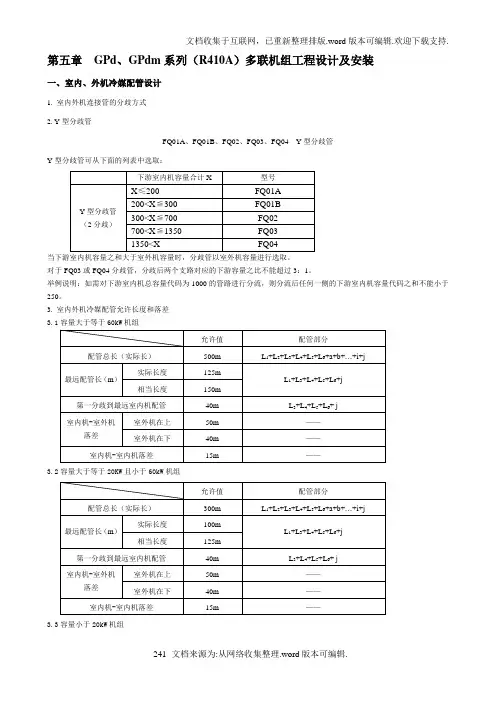
第五章GPd、GPdm系列(R410A)多联机组工程设计及安装一、室内、外机冷媒配管设计1. 室内外机连接管的分歧方式2. Y型分歧管FQ01A、FQ01B、FQ02、FQ03、FQ04 Y型分歧管Y型分歧管可从下面的列表中选取:当下游室内机容量之和大于室外机容量时,分歧管以室外机容量进行选取。
对于FQ03或FQ04分歧管,分歧后两个支路对应的下游容量之比不能超过3:1。
举例说明:如需对下游室内机总容量代码为1000的管路进行分流,则分流后任何一侧的下游室内机容量代码之和不能小于250。
3. 室内外机冷媒配管允许长度和落差3.1容量大于等于60kW机组3.2容量大于等于20KW且小于60kW机组3.3容量小于20kW机组4. 冷媒配管尺寸4.1 室外机至第1分歧间的配管(主管)尺寸由室外机容量代码来确定室外机至第1分歧间配管尺寸4.2 分歧部至分歧部间的配管(分歧管)尺寸根据下游所接室内机容量选定。
在超过室外机容量时,以室外机容量为准。
分歧部与分歧部之间配管尺寸4.3 分歧部至室内机间的配管(室内配管)尺寸同室内机配管尺寸相同,尺寸如下表所示:室内机配管尺寸5. 冷媒配管要求5.1 本机型使用工质为R410A,冷媒配管要求不可与其他工质配管混用。
5.2 连接管管材为紫铜TP2M,满足GB/T17791-1999《空调与制冷用无缝铜管》的要求。
5.3 铜管壁厚要求:单位:mm二、室外机模块间连接配管设计注:同一系统内各模块间距不小于20mm。
1、模块连接组件对于模块化并联室外机,模块连接组件用于连接各模块之间气管和液管。
可从下面的列表中选取:2、油平衡连接三通对于三机并联油平衡管路,需在油平衡管路中连接一个接口内径均为φ9.7的油平衡连接三通。
3、室外机模块间连接配管尺寸选择3.1室外机与连接组件间配管室外机与连接组件间配管尺寸与单个模块要求配管尺寸相同。
3.2 模块连接组件间配管如室外机为三机并联,则需考虑模块连接组件间配管。
格力中央空调工程调试验收规范(多联机组)

机组调试
• 3.调试准备
调试相关资料及准备工作确认
11 已经准备详细的电气,控制,管路设计图纸 22 已经记录好所有机组型号及条形码 33 已经记录制冷剂管长度和制冷剂灌注量 44 已经准备主要设备安装产品说明书及技术服务手册 55 客户及甲方验收人员是否能及时到位 66 工程施工单位是否可以提供必须的人力资源
开室内机,而是每隔5分钟依次增开1台室内机运行,直至全
开各室内机。 • 3、在系统运行无异常的情况, 30分钟后测量并记录各参数 • 4、转最小内机容量运行。 • 5、记录容量刚转换的时的各项参数, 30分钟后测量并记录
相关参数,最后保存监控软件数据,调试完毕。 • 6、在环境条件允许的前提下,在完成制冷模式的调试后可
客户服务中心 9 9
工程检查验收
二、机组安装验收
• 1、室外机组安装验收
• 1)室外机组的周边是否通风良好、回风、排风顺畅、有足 够的维修空间
• 2) 机组周围是否无强热源、电磁干扰源及其它可燃性气体 • 3) 室外机组是否安装在可靠承重的位置,是否有减震措施 • 4) 机身周围是否有排水道以排
除冷凝水 • 5) 室外机组固定是否牢固、是
GMV(L)-Pd***W/Na系列(8kw容量以下包括 直流变频H系列机型 8kw的机型除外)
交流变频H系列机型 GMV(L)-P***W/H(S)系列
一拖一风管机组
FG(R)**/A1、FG(R)**/A2系列
家用热水机组
KFRS-**/A系列
客户服务中心 31 31
便携式调试器
• 电源使用 12VDC,与 通讯使用同一 个接口。
其他机组 A1A2系列风管机、E系列风管机等
在上电情况下连接调试器,若连线接通后,调试器显示 屏仍未点亮,请立即断开,检查接口选择是否正确。
格力中央空调工程设计安装规范(多联机组)
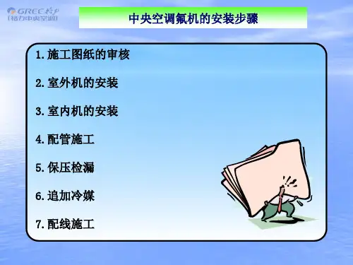
管道的试压
R22试压压力为 28公斤,410a试 压压力为40公斤。
多联机组施工——抽真空
控制线
低压表 高压表
真空计
气管 液管பைடு நூலகம்
压力表软管 室外侧进出口阀门A
真空泵
氮气
多联机组施工——抽真空
冷媒铜管标准
R22
管材 壁厚
O材
0.8
O材
0.8
O材
0.8
O材
1.0
O材
1.0
1/2H 1.0
1/2H 1.0
1/2H 1.0
1/2H
1/2H 1.3
1/2H
1/2H 1.5
1/2H
1/2H
1/2H 1.5
R410A
管材 壁厚
O材
0.8
O材
0.8
O材
0.8
O材
1.0
1/2H 1.0
1/2H 1.0
1/2H 1.0
保温厚度 ≥10mm ≥15mm ≥20mm
注:环境热而湿的场合上述厚度应增加。
多联机组施工——保温的类别
级 别
名称
说明
火焰离开即刻全 无燃烧,被烧部 B1 难燃材料 份 碳 化 、 无 收 缩 、 无高温熔滴、燃 烧时有烟气产生。
火苗离开后2S内
B2
阻燃、自 熄材料
自熄、被烧部份 明显收缩、有高 温熔滴、燃烧时
-
注:按照冷量的大小不同有不同的长度要求
铜管安装吊杆间距要求如下:
管道的支架
公称直径(㎜) 9.52 12 16 19 22 25 28 35 38 41
格力GMV多联空调机组室内机(R410A)
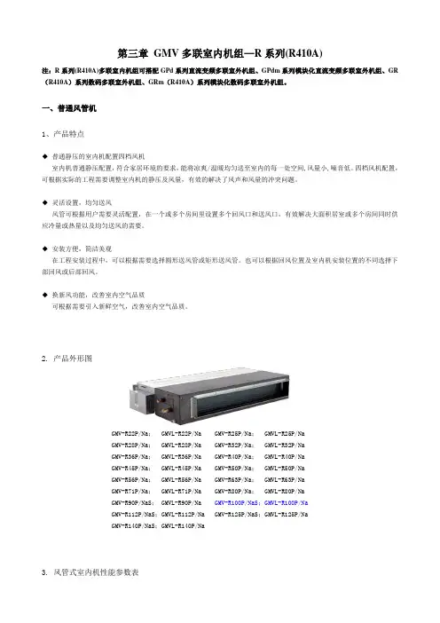
第三章 GMV多联空调机组室内机(R410A)注:GMV 多联空调机组室内机(R410A)可搭配GR 数码多联空调机组(R410A)、GRm 模块化数码多联空调机组(R410A)、GPd 直流变频多联空调机组、GPdm 模块化直流变频多联空调机组。
E 系列风管机所匹配外机仅限于直流变频机组。
双热源风管机所匹配外机仅限于直流变频模块化机组。
一、普通风管机1、产品概述室内机普通静压配置,符合家居环境的要求,能将凉爽/ 温暖均匀送至室内的每一处空间, 风量小, 噪音低。
四档风机配置,可根据实际的工程需要调整室内机的静压及风量,有效的解决了风声和风量的冲突问题。
◆灵活设置,均匀送风风管可根据用户需要灵活配置,在一个或多个房间里设置多个回风口和送风口,有效解决大面积居室或多个房间同时供应冷量或热量以及均匀送风的需要。
◆安装方便,简洁美观在工程安装过程中,可以根据需要选择圆形送风管或矩形送风管。
也可以根据回风位置及室内机安装位置的不同选择下部回风或后部回风。
◆换新风功能,改善室内空气品质可根据需要引入新鲜空气,改善室内空气品质。
2、产品外形图GMV-R22P/Na、 GMVR-R22P/ Na GMV-R25P/ Na、 GMVR-R25P/ NaGMV-R28P/ Na、 GMVR-R28P/ Na GMV-R32P/ Na、 GMVR-R32P/ NaGMV-R36P/ Na、 GMVR-R36P/ Na GMV-R40P/ Na、 GMVR-R40P/ NaGMV-R45P/ Na、 GMVR-R45P/ Na GMV-R50P/ Na、 GMVR-R50P/ NaGMV-R56P/ Na、 GMVR-R56P/ Na GMV-R63P/ Na、 GMVR-R63P/ NaGMV-R71P/ Na、 GMVR-R71P/ Na GMV-R80P/ Na、 GMVR-R80P/ NaGMV-R90P/ Na S、 GMVR-R90P/ Na GMV-R100P/ Na S、 GMVR-R100P/ NaGMV-R112P/ Na S、 GMVR-R112P/ Na GMV-R125P/ Na S、 GMVR-R125P/ NaGMV-R140P/ Na AS、GMVR-R140P/ Na A注:① .本机组设计执行标准GB/T 18837-2002。
2016年格力中央空调各系列最新价格表
12.7/6.35
65W
1.0×3
主体:840×840×190 面板:950×950×60
92
GMV-R63T/Na
9200
15.9/9.52
83W
1.0×3
主体:840×840×240 面板:950×950×60
93
GMV-R80T/Na
9760
15.9/9.52
83W
1.0×3
主体:840×840×240 面板:950×950×60
34.9/19.05
25/24
25.0×3+16.0×2
2580×880×1772
171
GMV-pd900W/NaB-N1
154321
34.9/19.05
28.31/26.52
25.0×3+16.0×2
2580×880×1772
系列
型号
价格
连接管
功率(W)
推荐电源线
外形尺寸
46
直流变频多联内机(R410A)
270W
1.0×5
1385×736×260
14
GMV-R100P/NaS
9532
15.9/9.52
270W
1.0×5
1385×736×260
15
GMV-R112P/NaS
9721
15.9/9.52
270W
1.0×5
1385×736×260
16
GMV-R125P/NaS
10180
15.9/9.52
270W
4811
9.52/6.35
55W
1.0×3
710×615×200
31
格力GPd直流变频多联空调机组相关说明
格力GPd直流变频多联空调机组注:GPd 直流变频多联空调机组搭配GMV 多联空调机组室内机(R410A)。
一、产品概述1、产品特点GPd 直流变频多联空调机组是格力自主研发的最新一代变频空调机组,是由一台风冷室外机连接数台相同或不同型式、容量的直接蒸发式室内机构成单一制冷系统,向一个或数个区域直接提供处理后空气的空调机组;机组容量范围为10.0kW ~ 90.0kW,其中20.0kW 以下容量机组主要用于家居场所、小型办公楼和商场等,而20.0kW 以上机组主要用于大型办公楼、生产车间、大型商场等商用场所。
机组采用技术领先的直流变频压缩机和独特的外观设计,并优化了制冷系统,使性能更佳、能效比更高、运行更为可靠,安装调试更为方便。
◆稳定可靠的系统设计a. 业界领先的直流变频正弦波驱动控制技术,压缩机更柔和和无级变速运行,强有力的保证了压缩机在各频率下的可靠运行和能力输出;b. 机组采用格力成熟的PI 算法控制技术,分别判断室内外温度,室内机能力,设定温度等不同条件决定压缩机的能力输出,与其他厂家同类产品所采用的简单的根据室内机能力决定压缩机的能力输出相比,格力变频多联机的运行频率连续平稳,冷媒分配更为精确,制冷速度更合理,环境温度与设定温度的差值更小;c. 机组可在宽温度范围连续可靠运行(室外温度:制冷10℃~ 48℃;制热-20℃~ 27℃),最大范围满足用户需求;d. 独特的系统控制,有效地避免了常规多联式空调在低负荷“大马拉小车”运行时带来的系统压力、温度、电流等异常问题,保证了系统在低负荷长期运行是安全、可靠的;◆直流变频技术, 高效节能a.格力直流变频机组,选用性能优越的高压腔直流变频压缩机,节能效率更高。
b. 由于交流变频所用压缩机中电机为交流电机,交流电机磁场的建立需要定子电流来建立,因此需要一部分损耗,即二次铜损;直流变频所用压缩机中电机为PMSM 或BLDC 电机,而PMSM 或BLDC 电机磁场是永磁体的,即没有二次铜损。
格力中央空调工程调试验收规范(多联机组)
工程检查验收
• 4、风管系统安装验收
• 1)送、回风口设计、气流组织是否合理 • 2)机组的机外静压是否与实际风管的阻力相匹配 • 3)风管系统是否装有送回风静压箱 • 4)风管的保温是否符合要求 • 5)风阀设置是否合理 • 6)回风口或室内机是否
装有过滤网并保证清洁 • 7)如果是天花回风是否
直接将系统转换为制热模式
客户服务中心 23 23
机组调试
• 6、调试最后一步:给与培训
• 指导操作员掌握启动/停机程序。 • 对业主进行系统培训,掌握制冷的基本知识,注意E7、
E2并不是一种故障,并提供解决方案。 • 对业主进行周期性保养培训:指导用户操作员掌握必要的
维护保养;并告知业主空调使用中做保养的好处和不做保 养的危害。 • 将相关表格的内容填写完整并移交业主,留下服务电话和 其它相关文件。
客户服务中心 9 9
工程检查验收
二、机组安装验收
• 1、室外机组安装验收
• 1)室外机组的周边是否通风良好、回风、排风顺畅、有足 够的维修空间
• 2) 机组周围是否无强热源、电磁干扰源及其它可燃性气体 • 3) 室外机组是否安装在可靠承重的位置,是否有减震措施 • 4) 机身周围是否有排水道以排
除冷凝水 • 5) 室外机组固定是否牢固、是
客户服务中心 19 19
机组调试
• 调试相关工具准备
真空泵
检漏仪
电子称
电流钳表
冷媒表
人字梯
笔记本电脑或 便携式调试器 电笔
协议转换器(USB/485) 内六角扳手
风速仪
活动扳手
噪音仪
十字螺丝刀
电子温度计
手电筒
客户服务中心 20 20
- 1、下载文档前请自行甄别文档内容的完整性,平台不提供额外的编辑、内容补充、找答案等附加服务。
- 2、"仅部分预览"的文档,不可在线预览部分如存在完整性等问题,可反馈申请退款(可完整预览的文档不适用该条件!)。
- 3、如文档侵犯您的权益,请联系客服反馈,我们会尽快为您处理(人工客服工作时间:9:00-18:30)。
外环传感器
F4
外化霜传感器
F5
排气传感器
线控外机显示代码
座吊机与线控显示用样
外机50、70、80和挂机故障
外机100.120和风管,天花机故障
外机双8
运行
制冷
制热
化霜1
08
化霜2
0A
制热过负荷
0C
闪3次
闪3次
闪3次
正常
0N
液阀温度传感器
内盘入口传感器
19次
气阀温度传感器
内机出口传感器
22次
缺氟或堵塞
F0
10次
内环传感器
内环传感器
1次
内盘传感器
内盘传感器
2次
外环传感器
外环传感器
F3
3次
外盘中传感器
外盘中传感器
F4
4次
排气传感器
排气传感器
F5
5次
回油
回油
F7
防冻保护
E2
2次
低压保护
低压保护
E3
3次
排气保护
排气保护
E4
4次
通信保护
通信保护
6次
模式冲突
模式冲突
7次
制冷过负荷
低电压保护
PL
3次
3次
3次
直流电压高保护
高电压保护
PH
3次
3次
3次
交流电输入电压异常
PP
3次
3次
3次
电容充电故障
充电回路故障
PU
17次
回油会化霜
回油会化霜
H1
1次
化霜
H1
快闪
压缩机过载保护
压缩机过载保护
H3
3次
IPM保护
IPM保护
H5
5次
压缩机失步
压缩机失步
H7
7次
PFC保护
PFC保护
HC
6次
功率模块过高保护
制冷过负荷
E8
8次
放冷风保护
水漫保护
E9
闪
闪
收福
收氟
F0
快闪
快闪
驱动模块复位
IPM复位
P0
3次
3次
3次
最小能力测试
制冷、热IPLV测试
P0
冷快闪
热快闪
能力测试
能力测试
P3
冷快闪
热快闪
相电流保护
压缩机电流保护
P5
15次
IPM与主板通信故障
IPM与主板通信故障
P6
16次
模块传感器故障
模块传感器故障
P7
18次
格力R410A多联机
代码
故障
E1
高压保护
E2
内机防冻保护
E3
低压保护
E4
排气保护
E5
变频过流保护
E6
通信故障
E7
模式冲突
E9
水漫保护
15、25、35、45、55
内环传感器
14、24、34、44、54
液阀温度传感器
12、22、32、42、52
内盘中间传温度感器
13、23、33、43、53
气阀温度传感器
模块温度保护
模块温度保护
P8
19次
交流接触器保护
交流接触器保护
P9
3次
3次
3次
电流传感器保护
电流传感器保护
PC
3次
3次
3次
传感器连接保护
传感器连接保护
Pd
3次
3次
3次
电流保护输入端
电流保护输入端
PA
3次
3次
3次
温漂保护
温漂保护
PE
3次
3次
3次
驱动板环境传感器
驱动板环境传感器
PF
3次
3次
3次
直流电压低保护
F8
8次
排气过高限频
F9
9次
防冻结保护限频
FH
2次
2次
压缩机退磁
HE
14次
内外机不配
LP
19次
压缩机相电流检测故障
U1
12次
直流电跌落故障
U3
20次
名义制冷。热
P1
最大制冷。热
P2
L9
20次
压缩机启动失败
压缩机启动失败
LC
11次
压缩机缺项
压缩机缺项
Ld
3次
3次
3次
压缩机堵转
压缩机堵转
LE
3次
3次
3次
超速
超速
LF
3次
3次
3次
外盘入管传感器
A5
3次
3次
3次
外盘处管传感器
A7
3次
3次
3次
芯片故障
EE
模块电流保护限频
EN
3次
3次
3次
模块温度保护限频
EU
6次
6次
过负荷限频
F6
6次
整机电流保护限频