信意电子0.96寸OLED模块使用手册
0.96寸OLED显示屏用户手册说明书

0.96inch OLEDUser Manual 1.Driver Chip SSD1306Interface 3-wire SPI、4-wire SPI、I2CResolution 128x64Display Size 0.96 inchDimension 29mm*33mmColors Yellow, BlueVisible Angle >160°Operating Temp. (℃) -20℃~70℃Storage Temp. (℃) -30℃~80℃2.We will illustrate the usage of the module with an example of 4-wire SPI mode (defaultworking mode) by connecting Waveshare Open103R development board (STM32V MCU onboard).2.1.Hardware configurationThis module provides 3 kinds of driver interfaces; they are 3-wire SPI, 4-wire SPI and I2C interface. In its factory settings, BS0/BS1 pins are set to 0/0 and 4-wire SPI is selected as default.Different working mode and pin function of the module can be set by hardware selection on BS0/BS1 pins. (Notice: In this operation, welding is required. Any changes under no guidance from Waveshare will be considered as a waiver of warranty).Table 1: Working mode setting122.2.Software configurationOpen the project file .\IDE\ OLED.uvproj in Keil, navigate to the following text, delete the ‘//’ (Double slash) before #define INTERFACE_4WIRE_SPI After compiling successfully, download the project to Open103R development board. Note: You should delete the ‘//’ (Double slash) corresponding to the mode selection2.3. Hardware connectionsConnect module to the SPI2 interface of Open103R development board, power up. OLED displays information as Figure 1 shows.Figure 1: OLED information display3. 4-wire SPI and I2C interfaces of SSD1306 OLEDThis module provides 3 kinds of driver interfaces. We introduce 4-wire SPI and I2C interfaceshere. You can read Chap. 8.1 from SSD1306-Revision_1.1.pdf for more details.The 4-wire serial interface consists of serial clock: SCLK, serial data: SDIN, D/C#, CS#. In 4-wire SPI mode,D0 acts as SCLK, D1 acts as SDIN. For the unused data pins, D2 should be left open. The pins from D3 to D7, E and R/W# (WR#)# can be connected to an external ground.Table 2: 4-wire SPI Control pins of 4-wire Serial interfaceNote(1) H stands for HIGH in signal(2) L stands for LOW in signalSDIN is shifted into an 8-bit shift register on every rising edge of SCLK in the order of D7, D6 0D/C# is sampled on every eighth clock and the data byte in the shift register is written to the Graphic Display Data RAM (GDDRAM) or command register in the same clock.Under serial mode, only write operations are allowed.Figure 2: Write procedure in 4-wire Serial interface modeThe I2C-bus interface gives access to write data and command into the device. Please referto Figure 2 for the write mode of I2C-bus in chronological order.a)Slave address bit (SA0)SSD1306 has to recognize the slave address before transmitting or receiving any information by the I2C-bus. The device will respond to the slave address following by the slave address bit (“SA0”bit) and the read/write select bit (“R/W#” bit) with the following byte format,b7 b6 b5 b4 b6 b2 b1 b00 1 1 1 1 0 SA0 R/W#“SA0” bit provides an extension bit for the slave address. Either “0111100” or3“0111101”, can be selected as the slave address of SSD1306. D/C# pin acts as SA0 for slave address selection. “R/W#” bit is used to determine the operation mode of the I2C-bus interface.R/W#=1, it is in read mode. R/W#=0, it is in write mode.b)I2C-bus data signal (SDA)SDA acts as a communication channel between the transmitter and the receiver. The data and the acknowledgement are sent through the SDA.It should be noticed that the ITO track resistance and the pulled-up resistance at “SDA” pinbecomes a voltage potential divider. As a result, the acknowledgement would not be possible to attain a valid logic 0 level in “SDA””SDAIN” and “SDAOUT” are tied together and serve as SDA. The “SDAIN” pin must be connected to act as SDA. The “SDAOUT” pin may be disconnected. When “SDAOUT” pin is disconnected, the acknowledgement signal will be ignored in the I2C-bus.c)I2C-bus clock signal (SCL)The transmission of information in the I2C-bus is following a clock signal, SCL. Each transmission of data bit is taken place during a single clock period of SCL.Table 3. I2C I2C-bus data format1)The slave address is following the start condition for recognition use. For the SSD1306, the slaveaddress is either “b0111100” or “b0111101” by changing the SA0 to LOW or HIGH (D/C pin acts as SA0).2)The write mode is established by setting the R/W# bit to logic “0”43)An acknowledgement signal will be generated after receiving one byte of data, including theslave address and the R/W# bit.4)After the transmission of the slave address, either the control byte or the data byte may be sentacross the SDA. A control byte mainly consists of Co and D/C# bits following by six “0” ‘s.a)If the Co bit is set as logic “0”, the transmission of the following information will containdata bytes only.b)The D/C# bit determines the next data byte is acted as a command or a data. If the D/C# bitis set to logic “0”, it defines the following data byte as a command. If the D/C# bit is set tologic “1”, it defines the following data byte as a data which will be stored at the GDDRAM.The GDDRAM column address pointer will be increased by one automatically after eachdata write.5)Acknowledge bit will be generated after receiving each control byte or data byte.5。
E01-ML01D产品使用手册.
nRF24L01P 无线模块E01系列本说明书可能会随着产品的不断改进有所更改,请以最新版的说明书为准成都亿佰特电子科技有限公司保留对本说明中所有内容的最终解释权及修改权产品概述E01系列是成都亿佰特公司标志性产品的 2.4G 无线模块, SPI 接口,目前已经稳定量产,并适用于多种应用场景。
E01系列采用挪威 Nordic 公司原装进口的 nRF24L01P 芯片,所有阻容感器件均采用进口元器件,尤其是晶体,我们使用了高精度宽温晶体,保证其工业特性。
发射功率为 20dBm 的模块内置了 PA 功率放大器与 LNA 低噪声放大器,从而提高通信稳定性,延长通信距离;发射功率为 0dBm 的模块均采用进口器件, 优秀的设计亦保证了卓越的射频性能,是追求低功耗的客户首选。
E01系列均严格遵守 FCC 、 CE 、 CCC 等国内国外设计规范,满足各项射频相关认证,满足出口要求。
目录1. 技术参数 ································································································································································································3 1.1. 通用参数 . ......................................................................................................................................... .......................................... 3 1.2. 电气参数 . ......................................................................................................................................... .......................................... 3 1.2.1发射电流 ··················································································································································································3 1.2.2. 接收电流 ··············································································································································································3 1.2.3. 关断电流 ··············································································································································································3 1.2.4. 供电电压 ··············································································································································································4 1.2.5. 通信电平 ··············································································································································································4 1.3. 射频参数 . ......................................................................................................................................... .......................................... 4 1.3.1. 发射功率 ··············································································································································································4 1.3.2. 接收灵敏度··········································································································································································4 1.3.3. 推荐工作频率 ·····································································································································································5 1.4. 实测参数 . ......................................................................................................................................... (5)1.4.1. 实测距离 (5)2. 机械特性 ································································································································································································5 2.1. 尺寸图 ........................................................................................................................................... ............................................. 5 2.1.1. E01-ML01D ·········································································································································································5 2.1.2. E01-ML01DP4 ····································································································································································6 2.1.3. E01-ML01DP5 ····································································································································································7 2.1.4. E01-ML01IPX ······································································································································································7 2.1.5. E01-ML01S ··········································································································································································8 2.1.6. E01-ML01SP2 (9)2.1.7. E01-ML01SP4 (9)3. 推荐连线图 (10)4. 注意事项 (10)5. 生产指导 ..............................................................................................................................................................................................11 5.1. 回流焊温度 ........................................................................................................................................... . (11)5.2 回流焊曲线图 . ......................................................................................................................................... .. (11)6. 常见问题 ······························································································································································································12 6.1. 通信距离很近 ........................................................................................................................................... (12)6.2. 模块易损坏 ........................................................................................................................................... . (12)7. 重要声明 (12)8. 关于我们 (12)1. 技术参数 1.1. 通用参数1.2. 电气参数 1.2.1. 发射电流1.2.2. 接收电流1.2.3. 关断电流1.2.4. 供电电压1.2.5. 通信电平1.3. 射频参数 1.3.1. 发射功率1.3.2. 接收灵敏度1.4. 实测参数2. 机械特性 2.1. 尺寸图 1.3.3. 推荐工作频率1.4.1. 实测距离2.1.1. E01-ML01D 2.1.2. E01-ML01DP42.1.3. E01-ML01DP52.1.4. E01-ML01IPX2.1.5. E01-ML01S2.1.6. E01-ML01SP22.1.7. E01-ML01SP4nRF24L01P 无线模块引脚序号引脚名称 1 2 3 4 5 6 7 8 VCC CE CSN SCK MOSI MISO IRQ GND ★ E01 系列用户使用手册引脚方向供电电源,必须 2.0 ~ 3.6V 之间输入输入输入输入输出输出模块控制引脚模块片选引脚,用于开始一个 SPI 通信模块 SPI 总线时钟模块 SPI 数据输入引脚模块 SPI 数据输出引脚模块中断信号输出,低电平有效地线,连接到电源参考地关于模块的引脚定义、软件驱动及通信协议详见 Nordic 官方《nRF24L01P Datasheet》★引脚用途 3. 推荐连线图序号 1 2 模块与单片机简要连接说明(上图以 STM8L 单片机为例) CE 可以长期接高电平,但是模块写寄存器时必须首先设置为 POWER DOWN 掉电模式,推荐 CE 用单片机引脚控制。
FXA模块说明书
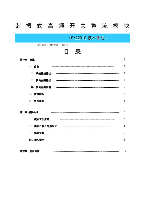
谐振式高频开关整流模块(F X22010技术手册)国电南京自动化股份有限公司目录第一章概述-------------------------------------------------------------------------- 1一、前言-------------------------------------------------------------------------- 1二、系统性能特点----------------------------------------------------------------- 1三、模块主要特点----------------------------------------------------------------- 1四、模块主要功能----------------------------------------------------------------- 2五、技术指标--------------------------------------------------------------------- 4六、型号命名--------------------------------------------------------------------- 5第二章模块构成----------------------------------------------------------------------- 5一、模块工作原理----------------------------------------------------------------- 5二、模块外观及外形尺寸-------------------------------------------------------- 6三、模块安装---------------------------------------------------------------------- 7四、操作说明----------------------------------------------------------------------- 9第三章使用环境-------------------------------------------------------------------- 15第一章概述一、前言当前我国电力系统使用的直流系统大部分采用传统的全桥软开关技术,开关频率是一个恒定值,只在某个输出电流值实现了软开关技术。
0.96寸oled显示屏使用手册
0.96寸OLED显示屏使用手册前言随着科技的不断发展,OLED显示屏作为一种新型的显示技术已经逐渐成为各种电子产品的标配。
其色彩饱和度高、对比度优秀、响应速度快等特点,使得它在智能穿戴设备、便携设备、医疗设备等领域得到了广泛的应用。
本手册将介绍0.96寸OLED显示屏的使用方法及注意事项,帮助用户更好地了解和操作该显示屏。
一、产品概述0.96寸OLED显示屏是一种小尺寸的OLED显示屏,通常用于智能手环、智能手表、可穿戴设备、小型医疗设备等产品中。
它采用了OLED(有机发光二极管)技术,具有超薄、低功耗、高对比度等特点,能够在低电压下实现高亮度显示。
该显示屏具有128x64像素的分辨率,支持SPI和I2C两种通信方式,便于与各种微控制器或单片机进行连接。
二、使用准备在使用0.96寸OLED显示屏之前,首先需要准备以下设备和材料:1. 0.96寸OLED显示屏模块2. 微控制器或单片机(例如Arduino、Raspberry Pi等)3. 杜邦线或排针4. 电源供应器(如果需要外部供电)三、连接方法0.96寸OLED显示屏通常通过SPI或I2C接口与微控制器或单片机连接。
以下是连接方法的具体步骤:1. 将0.96寸OLED显示屏模块的VCC引脚接到电源正极,将GND引脚接到电源负极,确保接线正确并稳固。
2. 根据所采用的通信方式,将SCL和SDA引脚(对于I2C通信方式)或DC和RES引脚(对于SPI通信方式)连接到微控制器或单片机相应的引脚上。
3. 如需外部供电,连接合适的电源供应器并接通电源。
四、调试与显示连接完成后,可以通过编写程序来控制0.96寸OLED显示屏的显示内容。
以下是一个简单的Arduino示例代码:```#include <Wire.h>#include <Adafruit_GFX.h>#include <Adafruit_SSD1306.h>#define OLED_RESET -1Adafruit_SSD1306 display(128, 64, &Wire, OLED_RESET);void setup() {display.begin(SSD1306_SWITCHCAPVCC, 0x3C);display.display();delay(2000);display.clearDisplay();}void loop() {display.setTextSize(1);display.setTextColor(SSD1306_WHITE);display.setCursor(0,0);display.println("Hello, World!");display.display();delay(1000);display.clearDisplay();}```通过以上示例代码,您可以实现在0.96寸OLED显示屏上显示“Hello, World!”的效果。
HG96 系列说明书

目录
HG9620
1. HG9620 智能配电仪表性能特点 ............................................................................................1 1.1 HG9620 智能配电仪表实时测量的参数范围 ........................................................................1 1.2 HG9620 智能配电仪表实时累积的电能参数范围 ................................................................1 1.3 HG9620 智能配电仪表的接口 ...............................................................................................1 2. 技术参数.....................................................................................................................................2 2.1 输入信号...................................................................................................................................2 2.2 测量精度......................................................................
OLED 模块 使用说明

OLED模块使用说明杭州海视方电子科技(VIP客户版,第一手资料,请勿外传。
所有资料均以官方数据为准,此文仅供参考,谢谢!)2014年12月22日重要提示:OLED屏裸露,玻璃板易碎,使用过程中请勿用力挤压、猛烈撞击,以免造成模块损坏!一、OLED简介:OLED,即有机发光二极管(Organic Light-Emitting Diode),又称为有机电激光显示(Organic Electroluminesence Display,OELD)。
因为具备轻薄、省电等特性,因此从2003年开始,这种显示设备在MP3播放器上得到了广泛应用,而对于同属数码类产品的DC 与手机,此前只是在一些展会上展示过采用OLED屏幕的工程样品。
自2007年后,寿命得到很大提高,具备了许多LCD不可比拟的优势。
二、0.96寸模块板子尺寸:SPI接口IIC接口三、1.3寸SPI接口模块尺寸图SPI接口IIC接口四、外观三种颜色任你选:蓝色、白色、蓝黄双色五、通讯模式:4线SPI、IIC接口六、SPI电路连接GND:电源地VCC:2.2V~5.5VSCL(D0):CLK时钟(高电平2.2V~5.5V)SDA(D1):MOSI数据(高电平2.2V~5.5V)RST:复位(高电平2.2V~5.5V)D/C:数据/命令(高电平2.2V~5.5V)兼容3.3V和5V控制芯片的I/O电平(无需任何设置,直接兼容)板子管脚依次为G(地),3.3V/5V(电源),SCL(CLK时钟),SDA(MISO数据),RES(复位),DC(数据/命令单片机采用 3.3V/5V电压的接线模式,下图以XS128单片机接线图为例:其他单片机只要有4个IO口就可以驱动移植程序非常简单:驱动程序以标准的.C.H文件写出,轻松移植七、IIC电路连接IIC接口:GND:电源地VCC:2.2V~5.5VSCL:CLK时钟(高电平2.2V~5.5V)SDA:MOSI数据(高电平2.2V~5.5V)注意事项:OLED显示屏不同于LCD,OLED上电是没有反应的,需要程序驱动才会有显示!。
0.96寸OLED液晶屏模块
0.96寸OLED显示屏一、OLED简介OLED,即有机发光二级管(Organic Light Emitting Diode)。
OLED由于同时具备自发光,不需背光源、对比度高、厚度薄、视角广、反应速度快、可用于扭曲性面板、使用温度范围广、构造及制作较简单等优异的特性,被认为是下一代的平面显示器新兴应用技术。
LCD都需要背光,而OLED不需要,因为它是自发光的。
这样同样的显示,OLED效果要来得好一些。
以目前的技术,OLED的尺寸还难以大型化,但是分辨率确可以做到很高。
在此我们使用的是中景园电子的0.96寸OLED显示屏,该屏有以下特点:1、0.96寸OLED有黄蓝、白、蓝三种颜色可以选择,其中黄蓝是屏上1/4部分为黄光,下3/4位蓝光,而且是固定区域显示固定颜色,颜色和显示区域均不能修改。
白光则为纯白,也就是黑底白字。
蓝光则为纯蓝,也就是黑底蓝字。
2、分辨率为128*64,每个像素都是一个LED。
3、多种接口方式,OLED裸屏的接口方式有5种:6800、8080两种并行接口方式、3线或4线的串行SPI接口方式、I2C接口方式(只需要用到2根线就可以控制OLED了!),这5种接口方式是通过屏上的BS0~BS2来配置的。
4、中景园电子的屏开发了两种接口的DEMO板,接口分别为七针的SPI/I2C兼容模块,四针的I2C模块,两种模块都很方便使用,我们可以根据实际需求来选择不同的模块。
二、模块特点:1、0.96寸OLED裸屏外观裸屏为30Pin,从屏正面看左下角为1脚,右下角为30脚。
在设计的时候一定要注意不要弄反了。
具体的接口方式请大家查看0.96寸OLED官方数据手册,里面有详细介绍。
2、0.96寸OLED模块(1)SPI/I2C接口模块(7脚)(2)I2C接口模块(4脚)3、0.96寸OLED的驱动IC芯片(SSD1306)本屏所用的驱动IC芯片为SSD1306,其具有内部升压功能,所以在设计的时候就不需要再专门设计升压电路了。
CRIO-4010 单相、三相全参数交流 电量采集模块 用户手册说明书
CRIO-4010单相、三相全参数交流电量采集模块用户手册版本号:Q7-30-02修订日期:2016-11-1国控精仪(北京)科技有限公司2016年版权所有本软件文档及相关套件均属国控精仪(北京)科技有限公司所有,包含专利信息,其知识产权受国家法律保护,除非本公司书面授权许可,其他公司、组织不得非法使用和拷贝。
为提高产品的性能、可靠性,本文档中的信息如有完善或修改,恕不另行通知,客户可从公司网站下载或致电我们通过电子邮件索取,制造商无需作成承诺和承担责任。
客户使用产品和软件文档进行设备调试和生产时,应进行可靠性、功能性等全面测试,方可进行整体设备的运行或交付。
我们提供7*24电话技术支持服务,及时解答客户问题。
如何从国控精仪获得技术服务我们将为客户提供满意全面的技术服务。
请您通过以下信息联系我们。
国控精仪公司信息网址: 英文中文销售服务: **************销售分机:801 电话: 400 9936 400 ************传真: ************地址: 北京市海淀区安宁庄东路18号2号办公楼420-423室请将您下列的信息通过邮件或传真发送给我们1概述...................................................................................................................................... - 1 -1.1产品特性.................................................................................................................. - 1 -1.2产品应用.................................................................................................................. - 1 -1.3产品详细指标.......................................................................................................... - 2 -1.3.1电量参数...................................................................................................... - 2 -1.3.2系统稳定时间.............................................................................................. - 2 -1.3.3物理特征...................................................................................................... - 3 -1.3.4产品功耗(典型值) ..................................................................................... - 3 -1.3.5工作环境...................................................................................................... - 3 -1.3.6存储环境...................................................................................................... - 3 -1.4软件支持.................................................................................................................. - 3 -2设备安装.............................................................................................................................. - 5 -2.1产品开箱.................................................................................................................. - 5 -2.2软件安装.................................................................................................................. - 5 -2.3产品布局图.............................................................................................................. - 6 -3信号连接说明...................................................................................................................... - 7 -3.1连接器管脚分配...................................................................................................... - 7 -3.2电源与通讯连接...................................................................................................... - 8 -3.3信号连接.................................................................................................................. - 9 -4 模拟量输入(AI)模块功能码........................................................................................ - 10 -4.1读保持寄存器........................................................................................................ - 10 -4.2读输入寄存器........................................................................................................ - 11 -4.3设置单个保持寄存器............................................................................................ - 13 -4.4设置多个保持寄存器............................................................................................ - 13 -5产品注意事项、保修、校准............................................................................................ - 15 -图2-1 CRIO4010产品图................................................................................................... - 6 -图3-1 电源与通讯接线图 ................................................................................................ - 8 -图3-2 单相电示意图 ........................................................................................................ - 9 -图3-3 三相电示意图 ........................................................................................................ - 9 -表3-1 16P端子标注 .......................................................................................................... - 8 -1概述CRIO-4010是基于RS485的高性能通信模块。
0.96英寸IPS屏显示模块用户手册说明书
0.96inch LCD ModuleUser ManualOVERVIEWThis is a general LCD display Module, IPS screen, 0.96inch diagonal, 160x80 HD resolution, with embedded controller, communicating via SPI interface.Examples are provided for testing. Examples are compatible with Raspberry Pi (bcm2835, wiringPi and python), STM32 and ArduinoSPECIFICATIONOperating Voltage : 3.3VInterface : SPIType : TFTControl Driver : ST7735SResolution : 160 (V) RGB x 80 (H) mmViewing Area : 21.7 (V) x 10.8 (H) mmPixel size : 0.1356(V)x 0.135(H)mmDimension : 32.5 x 26.00 (mm)PINOUTOverview (1)Specification (1)Pinout (2)Hardware (5)Controller (5)Communication protocol (5)Demo codes (7)Download (7)Raspberry Pi (7)Copy to Raspberry Pi (7)Libraries install (8)Hardware connection (10)Running examples (10)Expected result (11)STM32 (12)Hardware connection (12)Expected result (12)Arduino (13)Hardware connection (13)Expected result (13)FAQ (14)CONTROLLERST7735S is a controller for 162 x RGB x132 LCD. Note that the resolution of this LCD module is 160(H)RGBx80(V) indeed.ST7735S supports RGB444, RGB565 and RGB666 three formats. This LCD module we use RGB565.Because that the first pixel of the LCD is different with the origin point of controller, therefore, we should offset the position when initialize the module: Horizontal: begin from the second pixel; Vertical: begin from the 27th pixel. Make sure that the display position of LCD is same as RAM.For most of the LCD controller, there are several interfaces for choosing, this module we use SPI interface which is fast and simple.COMMUNICATION PROTOCOLNote: It is not like the tradition SPI protocol, it only uses MOSI to send data from master to slave for LCD display. For details please refer to Datasheet Page 105. RESX: Reset, should be pull-down when power on, set to 1 other time.CSX: Slave chip select. The chip is enabled only CS is set LowD/CX: Data/Command selection; DC=0, write command; DC=1, write dataSDA: Data transmitted. (RGB data)SCL: SPI clockThe SPI communication protocol of the data transmission uses control bits: clock phase (CPHA) and clock polarity (CPOL):CPOL defines the level while synchronization clock is idle. If CPOL=0, then it is LOW. CPHA defines at wh ish clock’s tick the data transmission starts. CPHL=0 – at the first one, otherwise at the second oneThis combination of two bits provides 4 modes of SPI data transmission. The commonly used is SPI0 mode, i.e. GPHL=0 and CPOL=0.According to the figure above, data transmitting begins at the first falling edge, 8bit data are transmitted at one clock cycle. It is SPI0. MSB.DOWNLOADVisit Waveshare wiki and search for 0.96inch LCD Module. Download the demo code:Extract and get the folders as below:Arduino: For Arduino UNORaspberry Pi: Includes three examples, BCM2835, WiringPi and PythonSTM32: For XNUCLEO-F103RB, which integrate STM32F103RBT6RASPBERRY PICOPY TO RASPBERRY PI1.Insert SD card which has Raspbian installed to your PC2.Copy RaspberryPi extracted to root directory (BOOT) of SD card3.Power on your Raspberry Pi and open Terminal, you can find that the examples islisted in boot directory4.Copy the RaspberryPi folder to /home/pi and change its execute permission.LIBRARIES INSTALLTo use the demo codes, you need to first install librariesInstall BCM2835:xx is the version of library. For example, if the library you download is bcm2835-1.52, the command should be : sudo tar zxvf bcm2835-1.52.tar.gzInstall wiringPi:Install Python libraries:HARDWARE CONNECTIONRUNNING EXAMPLESEnter the folder: cd RaspberryPi/bcm2835 example:Press Ctrl and C to stop running wiringpi example:Press Ctrl and C to stop running python example:Press Ctrl and C to stop running EXPECTED RESULT1.Clear screen2.Display number and strings3.Draw figures4.Display 40 x 40 image5.Display 160x80 imageSTM32The development board used is XNUCLEO-F103RB, based on HAL library HARDWARE CONNECTIONEXPECTED RESULT1.Clear screen2.Display number and strings3.Draw figures4.Display 40x40 image5.Display 160x80 imageARDUINOThis example is compatible with Arduino UNO HARDWARE CONNECTIONEXPECTED RESULT1.Clear screen2.Display number and strings3.Display figures4.Display 40x40 imageFAQ1.How to control backlight?- You can use the function LCD_SetBacklight() to control the backlight2.Why the LCD is black when working with Raspberry Pia) Check if SPI interface was enabledb) Check if the BL pin work normally, if the pin has no output, please try todisconnect the BL control pin3.What does it happen if using Raspberry Pi improperly?If you run python or bcm2835 examples after wiringPi, the LCD may cannot work normally, please try to restart Raspberry Pi can try again.4.How to rotate display?-You can use the function Paint_SetRotate(Rotate) to rotate display. Rotate should be 0, 90, 180 or 270.-Python can call rotate(Rotate) function for any angle.5.Python Image library- For some of the OS, you should execute command to install python-imaging library: sudo apt-get install python-imaging。
0.96寸)LED模块IIC控制
Write mode for I2C1)The master device initiates the data communication by a start condition. The definition ofthe startcondition is shown in Figure 8-8. The start condition is established by pulling the SDA from HIGH toLOW while the SCL stays HIGH.1)主设备通过一个启动条件启动数据通信。
开始条件的定义如图8-8所示。
启动条件是通过将SDA从高到低,而SCL保持高位时建立的。
2) The slave address is following the start condition for recognition use. For the SSD1306, the slaveaddress is either “b0111100” or “b0111101” by changing the SA0 to LOW or HIGH (D/C pin acts asSA0).2)从机地址在开始条件下进行识别使用。
对于SSD1306,通过将SA0更改为低或高(d/c pin为SA0),该从属地址是“b0111100”或“b0111101”。
2)The write mode is established by setting the R/W# bit to logic “0”.3)An acknowledgement signal will be generated after receiving one byte of data, includingthe slaveaddress and the R/W# bit. Please refer to the Figure 8-9 for thegraphicalrepresentation of theacknowledge signal. The acknowledge bit is defined as the SDA line is pulled down during the HIGHperiod of the acknowledgement related clock pulse.5) After the transmission of the slave address, either the control byte or the data byte may be sent acrossthe SDA. A control byte mainly consists of Co and D/C# bits following by six “0” …s.a. If the Co bit is set as logic “0”, the transmission of the following information will containdata bytes only.如果将Co位设置为逻辑“0”,那么以下信息的传输将仅包含数据字节。
- 1、下载文档前请自行甄别文档内容的完整性,平台不提供额外的编辑、内容补充、找答案等附加服务。
- 2、"仅部分预览"的文档,不可在线预览部分如存在完整性等问题,可反馈申请退款(可完整预览的文档不适用该条件!)。
- 3、如文档侵犯您的权益,请联系客服反馈,我们会尽快为您处理(人工客服工作时间:9:00-18:30)。
信意电子0.96寸OLED模块说明书
目录
一、OLED技术特点 (2)
二、OLED模块介绍 (2)
三、0.96寸OLED模块特点 (5)
四、管脚定义 (5)
五、客户应用案例 (6)
一、OLED技术特点
(1)OLED器件的核心层厚度很薄,厚度可以小于1mm,为液晶的1/3。
(2)OLED器件为全固态机构,无真空,液体物质,抗震性好,可以适应巨大的加速度,振动等恶劣环境。
(3)主动发光的特性使OLED几乎没有视角限制,视角一般可达到170度,具有较宽的视角,从侧面也不会失真。
(4)OLED显示屏的响应时间超过TFT—LCD液晶屏。
TFT—LCD的响应时间大约使几十毫秒,现在做得最好的TFT—LCD响应时间也只有12毫秒。
而OLED显示屏的响应时间大约是几微秒到几十微秒。
(5)OLED低温特性好,在零下40摄氏度都能正常显示,目前航天服上也使用OLED作为显示屏。
而TFT—LCD的响应速度随温度发生变化,低温下,其响应速度变慢,因此,液晶在低温下显示效果不好。
(6)OLED采用有机发光原理,所需材料很少,制作上比采用液体发光的液晶工序少,液晶显示屏少3道工序,成本大幅降低。
(7)OLED采用的二极管会自行发光,因此不需要背面光源,发光转化效率高,能耗比液晶低,OLED能够在不同材质的基板上制造,厂家甚至可以将电路印刷在弹性材料上——做成能弯曲的柔软显示器。
(8)低电压直流驱动,5V以下,用电池就能点亮。
高亮度,可达300明流以上。
二、OLED模块介绍:
1、OLED模块显示效果图:
图一:蓝色0.96寸OLED显示效果
图二:白色0.96寸OLED显示效果
图三:黄蓝双色0.96寸OLED显示效果
0.96寸OLED屏幕详细尺寸:
信意电子的0.96寸OLED模块采用高亮度,低功耗的OLED屏,显示颜色纯正,在阳光下有很好的可视效果。
模块供电可以是3.3V也可以是5V,不需要修改模块电路,同时兼容2种通信方式:4线SPI、IIC,通信模式的选择可以通信两个零欧电阻来跳选。
该模块一共有三种颜色:蓝色、白色、黄蓝双色。
OLED屏具有多个控制指令,可以控制OLED的亮度、对比度、开关升压电路等指令。
操作方便,功能丰富。
同时为了方便应用在产品上,预留4个M2固定孔,方便用户固定在机壳上。
三、0.96寸OLED模块特点
1、高分辨率:128X64(和12864LCD相同分辨率,但该OLED屏的单位面积像素点更多)
2、超广可视角度:大于160°(显示屏中可视角度最大的一种屏幕)
3、超低功耗:正常显示时0.06W(远低于TFT显示屏)
4、宽供电范围:直流3V-5V(无需任何改动,直接兼容常用的3.3V和5V供电系统)
5、工业级:工作温度范围-30℃~70℃
6、超小体积:(长)27.8MM*(宽)27.3MM*(厚)4.3MM
7、支持多种操作方式:4线SPI、IIC
8、带片选CS信号,可以实现多个SPI或IIC设备在同一总线工作
9、兼容3.3V和5V控制芯片的I/O电平(无需任何设置,直接兼容)
10、亮度、对比度可以通过程序指令控制
11、使用寿命不少于16000小时
11、OLED屏幕内部驱动芯片:SSD1306
四、管脚定义
信意电子0.96寸OLED模块管脚定义:
GND:电源地
VCC:供电电源3.3V、5V都可以
D0:串行输入时钟CLK
D1:串行输入数据
RES:复位
DC:控制输入数据/命令(高电平(1)为数据,低电平(0)为命令)
五、客户应用案例
OLED显示屏的众多优点,在需要人机交换界面的地方已经逐渐代替了功耗大的TFT显示屏。
在工业控制领域,例如手持式工控手柄、测试仪器,例如电池测量仪、医疗领域,例如便携式医疗设备、数码产品领域,例如MP3、智能手表、电子烟等都采用了OLED显示屏。
客户应用案例1:智能手表样机(白色OLED)
得益于OLED的低功耗和在阳光下的能见度好,可以很好的应用在便携式穿戴数码产品上。
客户应用案例2:锂电电池组测试仪样机(黄蓝双色OLED)
淘宝:/。