GTAS-30B说明书(印刷版)
GTASB说明书印刷版

G T A S B说明书印刷版 IMB standardization office【IMB 5AB- IMBK 08- IMB 2C】目录第一章概述1.1产品介绍 (1)1.2产品外观 (2)1.3与安全有关的符号说明 (3)1.4警告标志的内容 (4)1.5安全注意事项 (4)1.6到货检查 (7)第二章产品规格驱动器规格 (8)电机规格 (9)隔离变压器 (14)第三章安装环境条件 (15)伺服驱动器安装 (16)伺服电机安装 (18)第四章接线标准接线 (20)端子功能 (22)O接口原理 (26)伺服电机接线 (29)第五章显示与操作键盘操作 (31).监视方式 (32)参数设置 (35)参数管理 (36)速度试运行 (39)运行 (39)电机测试 (40)其它 (40)第六章通电运行电源的连接 (41)通电试运行 (43)参数调整 (45)第七章参数参数一览表 (48)参数功能 (50)第八章报警与处理报警一览表 (59)报警处理方法 (60)第九章常见问题常见问题报警 (67)频繁出现Err-15、Err-30、Err-31、Err-32报警 (67)型号代码参数与电机对照表 (68)第一章概述产品简介:随着交流伺服技术的成熟稳定,产品性能不断提高,适应工业控制向高速度、高精度、高效率、数字智能化方向发展,同时随着伺服产品性价比的不断提升,伺服控制替代步进控制已成为产业发展趋势。
交流伺服技术已从军工航空航天领域广泛深入地渗透到各行各业,广泛应用于数控机床、纺织机械、轻工机械、网版印刷、包装机械、自动生产线等自动化领域。
GTAS系列交流伺服系统是国产全新一代全数字交流伺服系统,采用美国TI公司最新数字信号处理器DSP(TMS320F2407A)、大规模可编程门阵列(CPLD)和MITSUBISHI智能化功率模块(IPM)等当今最新技术设计,运用PID算法完成PWM控制,性能优异已达到国外同类产品的水平。
GTAS-30A、50A驱动器说明书
1
第 1 章 产品检查与安装
伺服驱动器附近有干扰设备时,对伺服驱动器的电源线以及控制 线有很大的干扰影响,使驱动器产生误动作。可以加入噪声滤波 器以及其它各种抗干扰措施,保证驱动器的正常工作。注意加入 噪声滤波器后,漏电流会增大,为了避免这个毛病,可以使用隔 离变压器。特别注意驱动器的控制信号线很容易受到干扰,要有 合理的走线和屏蔽措施。
5
2.4 标准连接
z 位置控制
第 2 章 接线
6
交流伺服驱动器使用手册
第 3 章 接口
3.1 GTAS-30A 驱动器电源端子 TB
表 3.1 电源端子 TB
端子号 端子记号 信号名称
功能
1
PE
系统接地
接地端子
2
R
主回路电源输 主回路电源输入端子
3
S
入三相
AC220V 50Hz
4
T
AC220V
注意:不要同电机输出端子 U、V、W 连接。
COIN ON:当位置偏差计数器数值在 设定的定位范围时,定位完成输出 ON (输出导通),否则输出 OFF(输出截 止)。
输出;(速 -
速度到达输出端子。
度控制方
COIN ON:当速度到达或超过设定的
式下)
速度时,速度到达输出 ON(输出导 通),否则输出 OFF(输出截止)。
10
交流伺服驱动器使用手册
蔽此功能,用户不用连此端子,
也能使 CCW 驱动允许。
8
交流伺服驱动器使用手册
13 CW 驱 动 RSTP Type1 CW(顺时针方向)驱动禁止输入端子。
禁止
RSTP ON :CW 驱动允许,电机可以
派贝克服装CAD操作手册2009

目录目录 (1)第一章系统介绍 (3)第一节派贝克®(PAYBACK)服装CAD系统简介 (3)第二节派贝克®(PAYBACK)服装CAD系统制作流程 (3)第三节派贝克®(PAYBACK)服装CAD系统的价值 (4)第二章软件操作说明(基础编) (5)第一节菜单栏介绍 (5)一.文件 (5)二.素材库 (5)三.输入 (7)四.系统设置 (9)五.尺码表 (11)第二节纸样中心 (12)一.纸样中心常用工具 (12)二.纸样中心专用工具 (15)I.画线工具组: (15)II.求点工具组: (18)III.专用工具组 (19)IV.点线编辑工具组 (21)V.省褶工具组; (23)VI.生成裁片 (26)第三节裁片中心 (26)一.裁片中心常用工具 (26)二.裁片中心专用工具 (29)I.裁片标识 (29)II.工艺线 (31)III.裁片分割 (32)IV.褶裥 (33)V.旋转修整 (34)VI.放码 (35)第四节排料中心 (38)一.设置 (38)二.排料 (39)三.显示 (40)四.检测 (41)五.清除 (41)六.对条格 (41)七.排料报告 (41)八.其它 (42)九.裁片区 (43)十.混排 (44)第五节打印输出 (44)一.绘图仪输出 (44)二.切割机输出 (46)三.打印机输出 (46)第六节文件格式转换 (47)一.PLT格式文件 (47)二.DXF格式文件 (47)I.打开DXF格式文件 (47)II.保存DXF格式文件 (47)三.裁床格式文件 (47)第七节帮助 (48)一.主题 (48)二.快捷键列表 (48)I.文件处理快捷键 (48)II.纸样中心快捷键 (48)III.显示快捷键 (48)IV.裁片中心快捷键 (49)V.排料中心快捷键 (49)三.关于 (49)第三章智能模式(高级编) (50)第一节纸样设计 (50)一.绘图功能 (50)二.编辑功能 (52)三.特殊功能 (55)四.右键菜单 (57)第二节裁片处理 (58)一.缝边标记 (58)二.缝角处理 (60)三.内部线及工艺线设置 (61)四.裁片分割 (62)五.移动裁片 (62)六.点放码 (62)七.右键菜单功能 (65)八.空白处右键功能 (67)第三节快捷键功能 (69)第四章实例 (69)第一节女短裙 (69)第二节女裤 (73)第三节女衬衫 (81)第四节八片开身西服 (86)第一章系统介绍第一节派贝克®(payback)服装CAD系统简介由上海千派服装科技有限公司最新推出的派贝克®(payback)智能服装CAD系统是至今为止智能化程度最高的服装CAD系统。
Armour Bodies 车身安装说明说明书

BODYWORK MOUNTING INSTRUCTIONSThank you for choosing Armour Bodies bodywork. Below is a set of general instructions to help guide you through mounting your bodywork. If you have any questions about your bodywork please contact Woodcraft at: 978-297-2977 Monday through Friday 9 am to 5 pm EST.PLEASE NOTE: IT IS IMPORTANT TO DRILL AND MOUNT BODYWORK BEFORE PAINTING. Armour Bodies is designed to work with the stock fairing bracket unless stated otherwise. If your fairing bracket, frame and/or sub-frame happen to be bent in any manner it will affect the fitment of the bodywork. If there is any question to whether your frame is straight it is recommended you bring your bike to a shop that specializes in frame alignment to get it checked. Make sure to read and understand all instructions before mounting bodywork. INSPECT ALL BODYWORK PIECES TO ENSURE NO DAMAGED HAS OCCURRED DURING SHIPPING. IF THERE ARE ANY ISSUES KEEP THE BOX THE KIT WAS SHIPPED IN AND CALL WOODCRAFT!Recommended tools for installation:Drill, stepped bit (often referred to as a Uni-bit, this is the best type of bit to use to drill fiberglass), masking tape, tape measure and/or ruler as well as a penciland/or marker.Pieces included in kit:Upper, Lower, Front Fender, Tail section, Underdraft (most kits), Tank Cover (Most Honda CBR models)Step 1: Upper and Lower FitmentFor most models we recommend mounting the upper to your motorcycle first. Proper positioning of the upper will ensure ease of fitment of the lower and straight seam lines on the motorcycle. Note: CBR 600RR/1000RR owners will need to start by mounting the tank cover.Important: Start with lining the upper with the ram air duct(s). Once the upper fairing is fitted around the air duct(s), loosely fasten the rear mount points. Loosely bolting the rear mounts will allow you to pivot the bodywork helping to line up the lower. (If your bike does not have ram air duct(s) use rear mounts and the help of a friend to line up the upper.)Next with your upper loosely in place, line up the lower and check for any interferences. (Note: Armour Bodies never knows what aftermarket exhaust manufacturers will do with their designs. Occasionally certain pipes may have interference issues and modifications are needed.) This is a good time to check the seam lines between the upper and lower making sure everything is perfect. If something needs to be tweaked a little this is the time to do it. The mating surfaces are where adjustments are to be made when putting the parts together.Step 2: Fastening the Upper to the LowerWoodcraft and its staff prefer the slide on style Dzus fasteners to fasten the lower to the upper, but the rivet style works equally as well. Most kits will use three fasteners on each side to attach the upper and lower, but some will only use two due to space availability.Make marks for your fasteners equal length apart. The wire clip part of the fastener will locate the center of the fastener hole approximately 10mm from the edge of the bodywork. Be sure to mark carefully where you would like your Dzus fasteners before drilling.Drill Option 1: Once you have marked where you would like to put your Dzus fasteners you can drill the upper and lower while on the bike. Be careful not to drill too far damaging critical parts of your motorcycle.Drill Option 2: Take the lower off, drill your holes, and remount the lower. Mark your fastener locations on the upper and take the lower off the bike to drill your fastener holes in the upper.With your holes drilled attach the clip section of the fastener to the upper. Once you have installed the clip section you can slide the stud portion through the lower and upper, give the stud a quarter turn and ensure the upper and lower are securely fastened.Step 3: Installing the WindscreenRemoving the upper from the bike will allow the fiberglass to conform to the windshield as necessary. Test fit windscreen to ensure all dimple holes marked for drilling are lined up. Drill upper and mount windscreen reusing the hardware from the stock windscreen.Step 4: Installing the TailSupersport Tail:Slide the tail section over the subframe to ensure all mount points line up. Next drill and reinstall your tail. Once the tail is mounted, line the underdraft section up to the bottom of the tail and drill in the pre-marked mounting holes.You have a few options to attach the underdraft and they all work well. Many people will use Dzus fasteners or zip ties to attach the underdraft. Both options secure the draft while still allowing quick removal.The method that we’ve found to work best is to attach the draft using small Suzuki pushpins part #09409-06314-5PK. Make sure to drill your hole to the size of the pin clasped NOT expanded otherwise they’ll just fall out.Superbike Tail:Armour Bodies superbike tails have either separate or attached seat pan that distributes your weight to the subframe when seated on the motorcycle. This piece MUST be installed when using the superbike tail for proper fitment. Some seat pans need to be bolted to the subframe while others are not able to and must be riveted to the tailBolted Pan: Bolt the seat pan to the subframe at the OEM mounting locations for the seat. Reinstall the tail and push down on the seat to make sure the seat pan properly supports it.Riveted Pan: If there is no obvious place to bolt the seat pan to drill 2-4 holes (depending on application) through the seat into the seat pan. Install pop rivets through the seat to hold the two pieces together.Next, finish installing the tail the same as the Supersport tail aboveStep 5: Installing the FenderLine the fender up to the mounting locations to confirm all locations line up. Drill and mount fender.Step 6: All DoneGo over your motorcycle once all the bodywork is mounted to make sure no mistakes were made. Once your bodywork is drilled and mounted it is ready to be removed for paint.Feedback: Woodcraft and Armour Bodies are committed to making the best products in the industry. If you like our products or feel there is something we could do better please let us know. Contact us at: **********************。
KOBE Range Hoods 德尔克斯系列产品安装指南与操作手册说明书
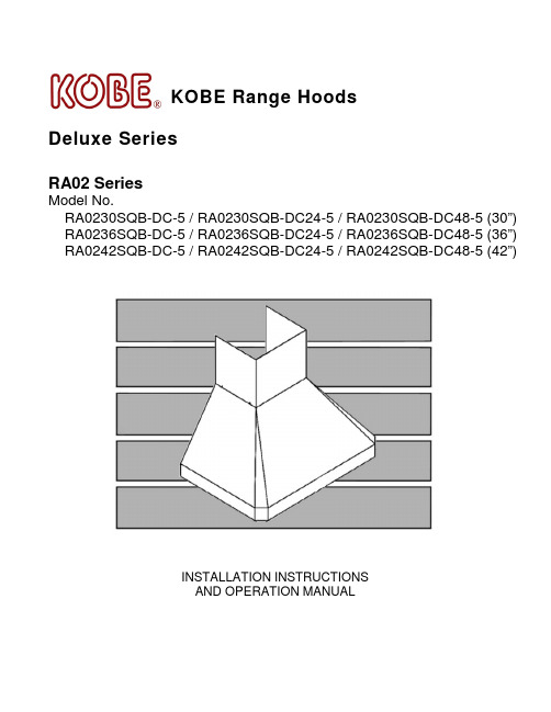
KOBE Range HoodsDeluxe SeriesRA02 SeriesModel No.RA0230SQB-DC-5 / RA0230SQB-DC24-5 / RA0230SQB-DC48-5 (30”) RA0236SQB-DC-5 / RA0236SQB-DC24-5 / RA0236SQB-DC48-5 (36”) RA0242SQB-DC-5 / RA0242SQB-DC24-5 / RA0242SQB-DC48-5 (42”)INSTALLATION INSTRUCTIONSAND OPERATION MANUALREAD BEFORE INSTALLATION1. Carefully check all contents of packages.2. Thoroughly inspect the unit for any shipping damages, cosmeticdamages or defects.3. Have a certified contractor/electrician test the unit before installation. IF THERE IS ANY PROBLEM:1. DO NOT INSTALL THE UNIT AND KEEP ALL ORIGINALPACKAGING MATERIAL.2. Have your original invoice as proof of purchase and product serialnumber ready.3. Contact your merchant for product replacement due to shippingdamages, cosmetic damages or defects.4. For other issues, email *********************************** orcall 1-626-775-8880 ext. 103, toll free 1-877-289-5623.1.2.3.[ENGLISH]- READ AND SAVE THESE INSTRUCTIONS -CONTENTSIMPORTANT SAFETY INSTRUCTIONS (1)COMPONENTS OF PACKAGE (3)INSTALLATION (4)OPERATION INSTRUCTIONS (8)MAINTENANCE (9)SPECIFICATIONS (10)MEASUREMENTS & DIAGRAMS (12)PARTS LIST (12)CIRCUIT DIAGRAM (16)TROUBLE SHOOTING (17)WARRANTY (18)PRODUCT REGISTRATION (20)- READ ALL INSTRUCTIONS CAREFULLY BEFORE STARTING -A L L W I R I N G M U S TB E D O N E B Y A P R O F E S S I O N A L A N D I NA C C O R D A N C E W I T H N A T I O N A L A N D L O C A L E L E C T R I C A L C O D E SIMPORTANT SAFETY INSTRUCTIONS- PLEASE READ THIS SECTION CAREFULLY BEFORE INSTALLATION - WARNING: TO REDUCE THE RISK OF FIRE, ELECTRIC SHOCK OR PERSONAL INJURY, OBSERVE THE FOLLOWING:1) Installation and electrical wiring must be done by qualified professionals and in accordance with allapplicable codes and standards, including fire-rated construction.2) When cutting or drilling into wall or ceiling, be careful not to damage electrical wiring or other hiddenutilities.3) Ducted fans must be vented to the outside.a) Before servicing or cleaning unit, open the light panel and SWITCH POWER OFF AT SERVICEPANEL.b) Clean all grease laden surfaces frequently. To reduce the risk of fire and to disperse air properly,make sure to vent air outside. DO NOT vent exhaust air into wall spaces, attics, crawl spaces or garages.NOTE - This warranty is invalid without an authorized agent’s receipt or if unit isdamaged due to misuse, poor installation, improper use, mistreatment,negligence or any other circumstances beyond the control of KOBERANGE HOODS authorized agents. Any repair carried out without thesupervision of KOBE RANGE HOODS authorized agents willautomatically void the warranty.- KOBE RANGE HOODS will not be held responsible for any damages topersonal property or real estate or any bodily injuries whether causeddirectly or indirectly by the range hood.WARNING: TO REDUCE THE RISK OF PERSONAL INJURY IN THE EVENT OF A RANGE TOP GREASE FIRE:1. Keep all fan, baffle/spacer/filter/oil tunnel/oil container and grease-laden surfaces clean. Greaseshould not be allowed to accumulate on fan, baffle/spacer/filter/oil tunnel/oil container.2. Always turn hood ON when cooking.3. Use high settings on cooking range ONLY when necessary.4. Do not leave cooking range unattended when cooking.5. Always use cookware and utensils appropriate for the type and amount of food prepared.6. Use this unit only in the manner intended by the manufacturer.7. Before servicing, switch power off at service panel and lock service panel (if possible) to preventpower from switching on accidentally.8.Clean ventilating fan frequently.What to Do In The Event Of a Range Top Grease Fire• SMOTHER FLAMES with a tight fitting lid, cookie sheet, or metal tray, and then turn off the burner.KEEP FLAMMABLE OR COMBUSTIBLE MATERIAL AWAY FROM FLAMES. If the flames do not go out immediately, EVACUATE THE AREA AND CALL THE FIRE DEPARTMENT or 911.• NEVER PICK UP A BURNING PAN – You May Get Burned.• DO NOT USE WATER, including wet dishcloths or towels – a violent steam blast will result.• Use an extinguisher ONLY if:a) You have a Class A, B, C extinguisher and know how to operate it.b) The fire is small and contained in the area where it started.c) The fire department has been called.d) You can fight the fire with your back to an exit.What to Do If You Smell Gas- Extinguish any open flame.- Do not try to turn on the lights or any type of appliance.- Open all doors and windows to disperse the gas. If you still smell gas, call the Gas Company and Fire Department right away.CAUTION1) For general ventilation use only. Do not use to exhaust hazardous or explosive materials and vapors.2) To reduce the risk of fire, use only metal ductwork. Sufficient air is needed for proper combustion andexhausting of gases through the flue (chimney) to prevent back drafting.3) Follow the heating equipment manufacturer’s guideline and safety standards such as those publishedby the National Fire Protection Association (NFPA), and the American Society for Heating, Refrigeration and Air Conditioning Engineers (ASHRAE), and code authorities.4) Activating any switch on may cause ignition or an explosion.5) Due to the size and weight of this hood, two people installation is recommended.ELECTRICAL SHOCK HAZARD – Can result in serious injury or death.Disconnect appliance from electric power before servicing. If equipped,the fluorescent light bulb contains small amounts of mercury, which mustbe recycled or disposed of according to Local, State, and Federal Codes.COMPONENTS OF PACKAGE(Must keep all material for returns or refunds){A} KOBE Range Hood{B} Warranty Registration Card{C} Quick Reference Guide{D} Oil Tunnel{E} Baffle Filter x 2 (30” & 36”)x 3 (42”){F} Spacer{G} 8” Round Exhaust Plate (42” only){H} Screws Package{I} Hood-Mounting Bracket{J} Screws Package{K} Duct Cover (Model No. RA02DC-1){L} Wire Cap{M} Screws Package{A}{B}{C}{D}{E}{F} {G}{H}{I} {J}{K} {L}{M}{N} Inner Duct Extension(Model No. RA02DC-24-1){O} Duct Cover Mounting Bracket{P} Screws Package{N} {O} {P}{Q} Outer Duct Extension(Model No. RA02DC-24){Q}- FOR MORE INFORMATION, PLEASE VISIT OUR WEBSITE OR CONTACT KOBE RANGE HOODS AT (626) 775-8880.Wire caps (3)M4 x 1-1/2” (4)M4 x 1-1/2” (2)30” & 36” 42”INSTALLATIONPLEASE READ ENTIRE INSTRUCTIONS BEFORE PROCEEDINGCalculation before InstallationCalculate the length of the installation, before installing the hood. (All calculation is measure in inches.)- FOR STAND ALONE -TABLE 1 ArrayA = Height of Floor to CeilingB = Height of Floor to Counter Top(Standard: 36”)C = Preferred Height of Counter Top to HoodBottom30” & 36” Hood (Recommended 27” to 30”)42” Hood (Recommended 30” to 36”)[(A – B] – (D + E)]D = Height of HoodE = Height of Duct CoverSAFETY WARNINGHOOD MAY HAVE VERY SHARP EDGES; PLEASE WEAR PROTECTIVE GLOVES IF IT ISNECESSARY TO REMOVE ANY PARTS FOR INSTALLING, CLEANING OR SERVICING.NOTE: BE CAREFUL WHEN USING ELECTRICAL SCREWDRIVER, DAMAGE TO THE HOODMAY OCCUR.NOTE: TO AVOID DAMAGE TO YOUR HOOD, PREVENT DEBRIS FROM ENTERINGTHE VENT OPENING.Decide the location of the venting pipe from the hood to the outside. (Figure 1)A straight, short venting run will allow the hoodto perform more efficiently.Try to avoid as many transitions, elbows, and long run as possible. This may reduce the performance of the hood.Temporarily wire the hood to test for proper operation before installingImportant:Peel protective film off the hood and the duct cover (if any).If necessary, prepare back wall frame with cross framing lumber for secure installation. Refer to Table 2 and measurements on Page 12 to decide the level of the lumber. (Figure 2)Loosen hood-mounting brackets at the back of the hood, adjust brackets and tighten screws.If necessary, remove the rubber stand on the back of the hood. (Figure 3)Figure 1 Figure 2 Figure 3CAUTION: If required to move the cookingrange to install the hood, turn off the poweron an electric range at the main electricalbox. SHUT OFF THE GAS BEFOREMOVING A GAS RANGE.1. Using references in Table 1 and measurementson Page 12, mark the leveling locations point for hood-mounting bracket on the wall.2. Secure two mounting screws (provided) to thewall, leaving an 1/8” space from the wall.3. Align the hood-mounting bracket to themounting screws on the wall and hang hood into place.4. Secure and tighten the mounting screws.CAUTION: MAKE SURE HOOD IS SECUREBEFORE RELEASING.Wiring to Power SupplySAFETY WARNINGRISK OF ELECTRICAL SHOCK. THIS RANGE HOOD MUST BE PROPERLY GROUNDED. MAKE SURE THIS IS DONE BY SPECIALIZED ELECTRICIAN IN ACCORDANCE WITH ALL APPLICABLE NATIONAL AND LOCAL ELECTRICAL CODES. BEFORE CONNECTING WIRES, SWITCH POWER OFF AT SERVICE PANEL AND LOCK SERVICE PANEL TO PREVENT POWER FROM BEING SWITCHED ON ACCIDENTALLY.5. Connect the electrical wires.- Connect three wires (black, white and green)to house wires and cap with wire connectors.Connect according to color: black to black,white to white, and green to green as shownon Figure 4.- If necessary to hide the electrical wireconnections, push wires back into the wiringbox. Access the wire connectionsunderneath the hood. To prevent anydamage, make sure wires do not slipbetween motor or any moving parts. Figure 4 Figure 5 Figure 66. Use 6” round steel pipe for 30” and 36” modelsor 8” round steel pipe for 42” model (follow building codes in your area) to connect the exhaust on the hood to the ductwork above.Use duct tape to make all joints secure and air tight. Refer Figure 5.7. Use four 4mm x 8mm screws (included) to attachduct cover to hood. Refer to Figure 6.8. Attach oil tunnel. Refer to Figure 7.9. Refer to Figure 23. Slide the baffle filter intothe hood. Push the baffle filter upward.Slide forward. Pull downward. Fit into place.10. Repeat until all baffle filters and spacers areresting against oil tunnel. Refer to page 8.11. Turn power ON in control panel. Check all lightsand fan operation.12. Make sure to leave this manual for thehomeowner. Figure 7 Figure 8OPERATION INSTRUCTIONSThis KOBE hood is equipped with two rotary controls with powerful centrifugal squirrel cage, baffle filters, and bright LED lights.The two rotary controls are Light Control & Speed Control. Refer to Figure 9.Figure 9Note: For best results, turn hood to QuietMode™ prior to preparation or cooking to establish airflow in the kitchen. Adjust speed as needed.Rotate the Speed Control clockwise to cycle from QuietMode™, Low, High, and Off;and rotate counterclockwise to cycle from High, Low, QuietMode™, and Off.Rotate the Light Control clockwise to turn on the light.MAINTENANCEFor the optimal level of operation, clean the range hood surface and baffles regularly.To Clean Hood SurfaceCAUTION: NEVER USE ABRASIVE CLEANERS, PADS, OR CLOTHS.*** Regular care will help preserve its fine appearance.1. Use only mild soap or detergent solutions. Dry surfaces using soft cloth.2. If hood looks splotchy (stainless steel hood), use an orange base cleaner to clean the surface ofthe hood. Avoid cleaner to get on the control switches. Only spread a light coating over the surface of the hood and leave on for a few minutes (do not leave on too long or this may cause damage to hood finish). Use soft towel to wipe off the cleaning solution, gently rubs any stubborn spots. Use a slightly damp towel to get rid of any cleaning solution. Use dry soft towel to dry the hood.3. To bring the glow back into a stainless steel finish, use a stainless steel cleaner.4. DO NOT allow deposits to remain for long periods of time.5. DO NOT use ordinary steel wool or steel brushes. Small bits of steel may adhere to the surfacecausing rust.6. DO NOT allow salt solutions, disinfectants, bleaches, or cleaning compounds to remain in contactwith stainless steel for extended periods. Many of these compounds contain chemicals, which may be harmful. Rinse with water after exposure and wipe dry with a clean cloth.To Clean Baffle Filters & Oil TunnelCAUTION: DRAIN BAFFLE FILTERS AND OIL TUNNEL BEFORE OIL WILL OVERFLOW.1. Remove the baffle filters and oil tunnel.2. Using a sponge, wash with warm soapy water. Dry completely before returning into place.(Note: Baffle Filters are top rack dishwasher safe.)SPECIFICATIONSMODEL / SIZE RA0230SQB-DC-5 / 30” / Single BlowerRA0236SQB-DC-5 / 36” / Single BlowerRA0242SQB-DC-5 / 42” / Dual BlowersRA0230SQB-DC24-5 / 30” / Single BlowerRA0236SQB-DC24-5 / 36” / Single BlowerRA0242SQB-DC24-5 / 42” / Dual BlowersRA0230SQB-DC48-5 / 30” / Single BlowerRA0236SQB-DC48-5 / 36” / Single Blower COLOR Commercial Grade Stainless Steel CONSUMPTION / AMPERE RA0230SQB-DC-5 – 320W / 2.86ARA0236SQB-DC-5 – 320W / 2.86ARA0242SQB-DC-5 – 350W / 3ARA0230SQB-DC24-5 – 320W / 2.86ARA0236SQB-DC24-5 – 320W / 2.86ARA0242SQB-DC24-5 – 350W / 3ARA0230SQB-DC48-5 – 320W / 2.86ARA0236SQB-DC48-5 – 320W / 2.86ARA0242SQB-DC48-5 – 350W / 3A VOLTAGE 120V 60HzNUMBER OF BLOWER 1 – 30”, 36”2 – 42”DESIGN 18-Gauge Seamless / Satin FinishFAN TYPE: CENTRIFUGAL Squirrel CageEXHAUST Top 6” Round – 30”, 36”Top 8” Round – 42”CONTROLS Rotary SwitchLIGHTS 3-Watt LED x 2 – 30”, 36”3-Watt LED x 3 – 42”HOOD DIMENSION (W x D x H) RA0230SQB-DC-5 29-3/4” x 24” x 18” RA0236SQB-DC-5 35-3/4” x 24” x 18” RA0242SQB-DC-5 41-3/4” x 24” x 18” RA0230SQB-DC24-5 29-3/4” x 24” x 18” RA0236SQB-DC24-5 35-3/4” x 24” x 18” RA0242SQB-DC24-5 41-3/4” x 24” x 18” RA0230SQB-DC48-5 29-3/4” x 24” x 18” RA0236SQB-DC48-5 35-3/4” x 24” x 18” RA0242SQB-DC48-5 41-3/4” x 24” x 18”DUCT COVER DIMENSION (W x D x H) 1) RA02DC-1 (Original Duct Cover)15” x 12” x 12”2) RA02DC-24-1 (Inner Duct Extension)15” x 12” x 24”3) RA02DC-24 (Outer Duct Extension)15” x 12” x 24”OPTIONAL ACCESSORIES (W x D x H) 1) 30” Stainless Steel Back PanelModel No.: SSP30 (30” x 32”) 2) 36” Stainless Steel Back PanelModel No.: SSP36 (36” x 32”)HOOD WEIGHT (lbs)Net Gross RA0230SQB-DC-5 55 67 RA0236SQB-DC-5 60 74 RA0242SQB-DC-5 75 91 RA02DC-1 5 7SPEED QuietMode™ Low High SINGLE BLOWERRA0230SQB-DC-5 RA0236SQB-DC-5 RA0230SQB-DC24-5 RA0236SQB-DC24-5 RA0230SQB-DC48-5 RA0236SQB-DC48-5 Air Capacity (cfm) 290 550 720 Sone* 1.8 4.7 5.4DUAL BLOWERSRA0242SQB-DC-5 RA0242SQB-DC24-5 RA0242SQB-DC48-5 Air Capacity (cfm) 450 700 1100 Sone* 2.5 6.0 8.0*One sone is equivalent to the sound of a refrigerator at 40 decibels. **Specifications subject to change without notice.MEASUREMENTS & DIAGRAMS*** All inch measurements are converted from millimeters. Inch measurements are estimated. *** All measurements in ( ) are millimeters.PARTS LISTMODEL NO.: RA0230SQB-DC-5 (30”)RA0236SQB-DC-5 (36”)RA0242SQB-DC-5 (42”)Inner Duct Extension Model No.: RA02DC-24-1 Baffle Filter for RA02 SQB-5 Series Outer Duct Extension Model No.: RA02DC-24 *Included in RA02 SQB-DC24-5 and SQB-DC48-5 Series *Included in RA02 SQB-DC48-5 Series onlyRA0236SQB-DC-5 / RA0236SQB-DC24-5 / RA0236SQB-DC48-5 (36”) RA0242SQB-DC-5 / RA0242SQB-DC24-5 / RA0242SQB-DC48-5 (42”)1 6” Round Plastic ExhaustRA0230SQB-DC-5RA0236SQB-DC-5L1-0505-0003 8” Round Exhaust Plate RA0242SQB-DC-5 L1-0505-00042 Duct Cover RA02DC-1 12-0200-012-613 LED Light (3W) L1-0403-03014 Valve Stem(LIGHT) L1-0405-0404-B 4A Valve Stem(ON/OFF) L1-0405-0402-B5 Knob L1-0405-0400-A6 Metal Oil Tunnel RA0230SQB-DC-5 B101-9130-14A Metal Oil Tunnel RA0236SQB-DC-5 B101-9136-14A Metal Oil Tunnel RA0242SQB-DC-5 B101-9142-14A7 Light Panel RA0230SQB-DC-5 B101-0230-06 RA0236SQB-DC-5 B101-0236-06 RA0242SQB-DC-5 B101-0242-068 Blower System RA0230SQB-DC-5RA0236SQB-DC-5X5-L1-0302-0120-802RO RA0242SQB-DC-5 X5-L1-0302-0120-802RE8A Motor Support RA0242SQB-DC-5 L1-0233-02429 Capacitor x 1PCSRA0230SQB-DC-5RA0236SQB-DC-5L1-0401-0120-24 Capacitor x 2PCS RA0242SQB-DC-5 L1-0401-0120-2410 LED Driver L1-0402-D00111 Capacitor Panel RA0230SQB-DC-5 L1-0201-0230 RA0236SQB-DC-5 L1-0201-0236 RA0242SQB-DC-5 L1-0201-024212 Baffle Filter L1-0214-019113 Stainless Steel Spacer {1-5/16”(33)x14-3/8”(365)} RA0230SQB-DC-5 B101-9130-15 Stainless Steel Spacer {4-5/16”(109)x14-3/8”(365)} RA0236SQB-DC-5 B101-9136-15 Stainless Steel Spacer {15/16”(23)x14-3/8”(365)} RA0242SQB-DC-5 B101-9142-15RA0236SQB-5 / RA0236SQB-DC24-5 / RA0236SQB-DC48-5 (36”)CIRCUIT DIAGRAMMODEL NO.: RA0230SQB-DC-5 / RA0230SQB-DC24-5 / RA0230SQB-DC48-5 (30”) RA0236SQB-DC-5 / RA0236SQB-DC24-5 / RA0236SQB-DC48-5 (36”)MODEL NO.: RA0242SQB-DC-5 / RA0242SQB-DC24-5 / RA0242SQB-DC48-5 (42”)TROUBLE SHOOTINGIssue Possible Cause SolutionAfter Installation, both motors and lights are not working. The power is not on. Make sure the circuit breaker and theunit’s power is ON. Use a voltage meterto check the power supply.The wire connection is not secure. Check and tighten wire connection. The control panel is defective. Replace the control panel.Lights are working, but motor(s) is not. The motor(s) is defective. Replace the motor.The capacitor(s) is defective. Replace capacitor(s).The control panel is defective. Replace the control panel.The range hood is vibrating. The blower system is not secure. Tighten the turbine impeller/squirrel cageand air chamber.The squirrel cage is not balanced. Replace the squirrel cage.Hood is not secured in place. Check the installation of hood, tighten themounting bracket.The motor is working, but the lights are not working. LED Light(s) is defective. Replace the LED light.The light wiring(s) is loose. Check wire continuity from lighttransformer to LED light housing(s). Light transformer is defective. Check power input and power output onthe light transformer. If it’s needed,replace the light transformer.The control panel is defective. Replace the control panel.The range hood is not venting out correctly. The range hood is installedoutside of the manufacturerecommended clearance.Adjust the clearance between the rangehoods and cook top to 27” to 30”. ForIsland range hood, the clearance betweenthe range hoods and cook top is 30” to36”.There is no make-up air inside thehouse.Open the window to enhance theperformance of the range hood bycreating a sufficient make-up air. Obstacle blocking the pipe work. Remove all obstacles from the duct work. The pipe size is smaller than thesuggested pipe size.Change the ducting according to themanufacture suggestion.Cold air is coming into the home. The pipe connection is notproperly sealed.Check the pipe installation.The damper is not properlyinstalled or is missing from theinstallation.Check the damper installation.The damper is not installed. By installing the damper, it will help toeliminate air backflow.WARRANTYWARRANTY CERTIFICATEIn order to obtain warranty service, you must provide proof of original purchase from a KOBE authorized Dealer. Please keep a copy of your original invoice as proof of purchase.ONE-YEAR LIMITED LABOR WARRANTY ON KOBE DELUXE SERIES:For one year from the date of your original invoice from a KOBE authorized dealer, we will repair any parts or components free of charge that failed due to manufacturing defects. KOBE reserves the right to replace, rather than repair the product free of charge at our sole discretion.It is your sole responsibility to ensure the product is readily accessible for the service technician to perform repairs. The service technician will not, under any circumstance, remove, alter or modify any fixture built around and/or connected to the product to gain access to perform repairs.TWO-YEAR LIMITED PARTS WARRANTY ON KOBE DELUXE SERIES:For two years from the date of your original invoice from a KOBE authorized dealer, we will provide non-consumable replacement parts or components free of charge that failed due to manufacturing defects. Consumable parts such as lights bulbs, filters, fuses, and oil cups are not covered by this warranty.WHAT IS COVERED:This warranty is valid in the United States and Canada. It is non-transferable and applies only to the original purchaser and does not extend to subsequent owner of this product. In Hawaii, Alaska and Canada, this warranty is limited. There may be additional shipping charges for parts and service technician travel costs in remote areas or locations 30 miles outside of KOBE authorized service area.WHAT IS NOT COVERED:1. Normal wear and tear, regular service and maintenance required for the product.2. Consumable parts such as light bulbs, filters, fuses, and oil cups.3. Chips, scratches or dents due to abuse or misuse of the product, use of corrosive andabrasive cleaning products.4. Damages caused by accident, fire, flood and other Acts of God.5. Services in remote areas or locations 30 miles outside of KOBE authorized service area.6. Labor cost incurred in connection with the removal of range hood, and reinstallation ofreplacement range hood, nor does it cover any other contingent expenses.7. Scratches inside the hood, back of the baffle filter, and inside the duct cover.THIS WARRANTY WILL BE VOIDED WHEN:1. Improper installation and failure to follow installation instructions.2. Any repair, alteration, modification not authorized by KOBE.3. Duct alteration, modification and connection.4. Incorrect electric current, voltage or wiring.5.Improper usage of the product such as commercially, outdoor or other usage other thanits intended purpose which is residential indoor usage only.6. Product is purchased from an unauthorized KOBE dealer.7. Product is damaged due to negligence, misuse, abuse, accident.If we determine that the warranty exclusions listed above applies or if you fail to provide all necessary documentation for warranty service, you will be responsible for all expenses associated with the requested service, including parts, labor, shipping, travelling, and any other expense related to the service request.TO REQUEST WARRANTY SERVICE, PLEASE CONTACT KOBE RANGE HOODS SERVICE CENTER:From the 48 contiguous states:Email (best): ***********************************Phone: 1-626-775-8880 ext. 103Toll Free: 1-877-BUY-KOBE (289-5623)From Alaska, Hawaii, and Canada:Email (best): ***********************************Phone: 1-626-775-8880 ext. 103WARRANTY INFORMATION FORMFill in the blanks and keep this paper with the original invoice in a safe place for future service purpose.1. Date of purchase :2. Model No. :3. Serial No. :For warranty service or spare parts purchase in US, contact: KOBE Service CenterEmail (best): ***********************************Phone: 1-626-775-8880 ext. 103Toll Free: 1-877-BUY-KOBE (289-5623)For Warranty service or spare parts purchase in Canada, contact: Email (best): ***********************************Toll Free: 1-626-775-8880 ext. 103Your notes:Deluxe SeriesKOBE Range Hoods11775 Clark StreetArcadia, CA 91006 USAThis KOBE hood is made for use in the USA and CANADA only. We do not recommend using this hood overseas as the power supply may not be compatible and may violate the electrical code of that country. Using a KOBE hood overseas is at your own risk and will void your warranty.Cette hotte KOBE est fabriquée pour usage aux États-Unis et au Canada seulement. Il n’est pas recommandé d’utiliser cette hotte à l’étranger puisque l’alimentation électrique pourrait ne pas être compatible et enfreindre le code de l’électricité de ce pays. L’usage de la hotte KOBE à l’étranger est à votre propre risque et la garantie sera annulée.Esta campana de extracción KOBE ha sido fabricada para ser utilizada únicamente en EE.UU. y CANADÁ. No recomendamos la utilización de esta campana en el extranjero debido a que la fuente de energía podría no ser compatible y podría violar el código eléctrico de dicho país. Utilizar una campana KOBE en el extranjero será a su propio riesgo y anulará la garantía.VER. 180208Information subject to change without notice.。
柏林汽车产品说明书
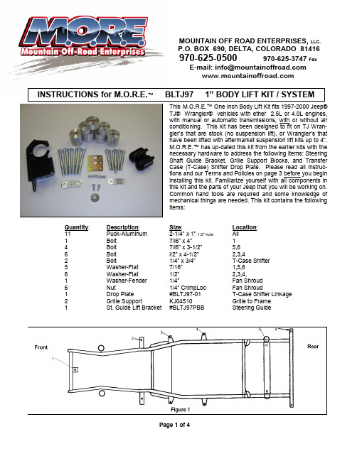
Quantity : Description : 11 Puck-Aluminum 1 Bolt 4 Bolt 6 Bolt 2 Bolt 5 Washer-Flat 6 Washer-Flat 1 Washer-Fender6 Nut 1 Drop Plate 2Grille Support1 St. Guide Lift BracketMOUNTAIN OFF ROAD ENTERPRISES, LLC. P.O. BOX 690, DELTA, COLORADO 81416 970-625-0500 970-625-3747 FaxE-mail:************************Page 1 of 41.Remove the 4 bolts holding the fan shroud to the radiator.2. Remove the 4 nuts that hold the fan to the water pump pulley.3. Remove the shroud and fan.4. Inside the Jeep on the drivers side, pull the carpet away from the floor pan to expose the 4 bolts thathold the transfer case shift linkage bracket. (This bracket is on the under side of the body and it's pur-pose is to locate the bellcrank for the linkage.) Remove the 4 bolts and remove the bracket from the un-der side.5. Loosen all 11 body mount bolts. Remove the one under the grille. Remove 5 bolts on the driver’s side.(Hint, The hidden mount bolts are between the fuel tank and the upper rear shock mount!).6.Place a stout piece of wood on a floor jack and place the jack between body mount 3 and 4 on the chan-nel portion of the body. Jack up the body just enough to install the 1 inch pucks on top of the factory steel washers/rubber insulators. Place the M.O.R.E.™ pucks in locations 2,3,4,5,6. It is recommended that you use a dab of lock-tight on the new longer bolts. Start the new longer bolts in locations 2,3,4,5,6. Do not tighten at this time. See Figure 1 for locations of body mounts.6A. If you are replacing the body mounts with our Urethane mounts then the position for these are : Positions :1,5, and 6 : MO2288 , M02429 , S10125 See Figure 1Positions : 2,3, and 4 : M02348 , MO2350 , S10125 See Figure 17. Repeat this procedure on the passenger side of the body.8. Install the last puck under the grille (location 1) and start the longer bolt.9.Remove the factory rubber grille supports and replace them with the supplied 1” taller urethane grillesupports. It is recommended to apply a lubricant to the urethane to help with the install.10. Now, tighten the new longer body mount bolts. Use your judgment as to how tight to torque the bolts. Donot "crush" the rubber insulators or leave the bolts too loose!11. Find the 4 holes in the mounting flange on the radiator where the shroud mounted. Measure 1 inch belowthe factory holes and center punch a mark. Do this as accurately as possible. (The passenger side lower hole will end up in a large existing hole and can not be drilled. (This is what the large fender washer is for.)12. Drill the center punched marks with a 1/4" drill bit. You may find it easier to use a angle-head drill for thisjob, however a standard drill can be used.13. Since the radiator stays in the stock location, and its bolted to the body, it moves up 1 inch with the bodylift. The fan shroud must line up with the fan, and it is connected to the engine. The engine stays in the stock location. For the shroud to fit in the new holes you just drilled, the shroud needs to be trimmed slightly to clear the lower radiator hose. You can use a round file, Dremmel® Tool (hi-speed grinder), or what ever you have to perform this job. The shroud is made out of a plastic material that cuts, sands and forms easily, so be careful when grinding or filing. Make sure that the shroud doesn't touch the hose when bolted in place.14. Install the fan and shroud. Tighten the nuts that hold the fan to the pulley/water pump. Install the factorybolts through the shroud and into the holes you drilled in the mounting flange. Use the CrimpLoc nuts provided. Do not over tighten the nuts/bolts, just a bit past snug will do the trick. The large fender washer is for the lower hole on the passenger side. Place it on the steel side of the mounting flange so the CrimpLoc nut has a surface to grab against.Page 2 of 4Figure 3bFigure 4Page 4 of 4Figure 5Figure 6Figure 7Now GoJeepin !。
迈阿密-伯南克-上车辅助系统-商务用品说明书

INSTALLATIONINSTRUCTIONSSingle Compartment Overhead Console #103Please read and fill out the enclosed warranty registration card toactivate your warranty.Shipment Contents103 Loop Bracket Footman Loop Bracket Electronics Support Frame Adjustable Support BracketLower Adjustment Piece Upper Adjustment Piece Main Console BodyShipping Package(4)6-32 Flathead Phillips (2)6-32 Unslotted Screws(2)10-32 Panhead Phillips(2)10-32 Flat Phillips(3)10-32 Buttonhead Screws (2)1/4-20x3/8 Socket Head Screws(3)3/16” Washers(2)1/4” Washers (4)5/16” Washers (2)5/16” Barrel NutsShipping Package (Continued)(2)10-32 Lock Nuts (4) 5/16” Lock Nuts (2) 1” Diaphragm Grommets(2) 5/16” U-Bolts (2)5/16-18x3” Carriage Bolts Rubber SealTOOLS NEEDED• 1/8” Allen Wrench• 3/16” Allen Wrench (Wranglers Pre 2003 without full roll cage only)• T-20 Torx Driver (Wranglers Pre 2001 only)• Small Phillips Screw Driver• 5mm Allen Wrench• ½” Socket and Ratchet – Extensions and Swivels are helpful (Vehicles with Roll Cage only) PLEASE READ ALL INSTRUCTIONS THOROUGHLY BEFORE STARTING INSTALLATION. These instructions will guide you through the installation of your new overhead console in the following vehicles:• Stock Jeep Wranglers 2000 or earlier• Stock Jeep Wranglers 2001-2002 (With Footman loop riveted to windshield)• Stock Jeep Wranglers and Rubicons 2003+ (With Large Oval Rollbar Pad)• Vehicles with a full roll cage and distance from front to rear bar between 28” to 36-1/2”If your vehicle does not fall into one of these categories you may have to make modifications to mounting brackets, and/or purchase additional hardware.1. Apply the Rubber Seal provided to the lid so that it will seal up against the console when closed.Check the lock operation.2. Route the wires for your stereo, CB, or speaker up along the rollbar and leave plenty of extra wire. Stock Jeep Wranglers 2000 or earlier3. Remove the footman loop from the top center of the windshield frame using a T-20 torx wrench. Saveall hardware.4. Using (2)10-32x1/2” Flat phillips machine screws and (2)10-32 Locknuts bolt the footman loop to theLower Adjustment Piece as shown in Figure 1.Stock Jeep Wranglers 2001-2002, Stock Jeep Wranglers and Rubicons 2003+, Vehicles with a full roll cage5. If you have a bikini top or if you plan to get a bikini top, you will need to purchase a footman loop.Most large hardware stores have footman loops in stock- You will need one with hole spacing of 2-1/4” center to center.6. Using (2)10-32x1/2” Flat phillips machine screws and (2)10-32 Locknuts bolt the footman loop to theLower Adjustment Piece as shown in Figure 1.7. Refer to Figure 2 and place the Upper and Lower Adjustment pieces around the rear rollbar. Noticethat the upper piece wraps outside of the lower piece on the top and sides. Also notice that that upper piece has nuts inserted, make sure that at the back of the two pieces that the upper piece is inside the lower piece, See Figure 3.8. Using the (2) 10-32x3/8” Panhead Phillips Machine Screws, loosely screw the two pieces together asshown in Figure 3.Stock Jeep Wranglers 2000 or earlier, Stock Jeep Wranglers 2001-2002, Vehicles with a full roll cage 9. Insert the 3” Carriage bolts through the Upper Adjustment Piece as shown in Figure 4. These will betightened later in the installation.10. With the pieces angled toward the floor slightly, carefully slide the console body over the Adjustmentpieces that have been sandwiched together.Stock Jeep Wranglers 2000 or earlier11. Carefully rotate the console up until the holes in the front of the console line up with the holes in thewindshield frame where the footman loop was. Use the original footman loop hardware to bolt the console to the windshield frame. BE CAREFUL NOT TO TEAR THE ROLLBAR PADDING! Stock Jeep Wranglers 2001-200212. Slip the footman loop bracket around the existing footman loop by inserting the bent flange on thebracket behind the footman loop from the top down. Carefully rotate the console up until the holes in the front of the console line up with the holes in the footman loop bracket. BE CAREFUL NOT TO TEAR THE ROLLBAR PADDING! Use the (2)1/4-20x3/8” Socket Head Cap Screws and (2)1/4”Washers to fasten the console to the bracket. See Figure 5.Stock Jeep Wranglers and Rubicons 2003+13. Place the 103 Loop Bracket over the hook at the top center of the windshield frame. Carefully rotatethe console up until the holes in the front of the console line up with the holes in the Loop Bracket. BE CAREFUL NOT TO TEAR THE ROLLBAR PADDING! Using the (2)1/4-20x3/8” Socket Head Cap Screws and (2)1/4” Washers bolt the console to the bracket. Using (1)10-32x1 Button Head Screw and (1) 3/16” Washer bolt the console through the hook to the Loop Bracket. Tighten until snug. See Figure 6.Vehicles with a full roll cage14. Carefully rotate the console up until you can use the (2)5/16” U-Bolts, (4)5/16” Washers, and (4) 5/16”Locknuts to bolt the console to the front rollbar.15. Use (2)10-32x1 Button Head Screws and (2)3/16” Washers to bolt the rear assembly to the mainconsole. There are nuts in the top of the console that these screws will go into. Do not over tighten.Over tightening will cause the top of the console to warp down. See Figure 7.Stock Jeep Wranglers Pre 2000, Stock Jeep Wranglers 2001-2002, Vehicles with a full roll cage16. Using the (2) 5/16” Barrel Nuts tighten down the rear assembly around the roll bar. Be sure to slidethe bolts as far back as possible up against the roll bar.17. Tighten the screws that you inserted in Step 10.18. Mount the Stereo, CB, or speaker to the removable electronics support frame if desired or yourelectronic equipment can be fastened directly to the console. Notice that there are holes on the back flange of the bracket for securing a stereo support strap or similar support device.19. Follow the manufacturer’s directions for connecting the supply wires to your electronic equipment.20. Slide the Support Frame up into the lockable compartment (you will have to rotate the camlock whileinserting the bracket) and fasten in place using (2)6-32 Flat head Phillips Machine Screws on the face of the bracket and (2)6-32 Unslotted Hexwasher Screws up through the bottom of the console into the bracket. Do not over tighten, these small diameter screws cannot withstand a lot of torque and will break if over-tightened. See Figure 8.21. Use the Adjustable Stereo/CB Support Bracket and (2)6-32 Flat Head Phillips Machine Screws tosecure the top of your electronic equipment.22. Install the 1” Grommets in the holes on both sides of the console. If you need to route a CBmicrophone or other cables through the hole simply slice the middle of the grommet.23. Lock it up!!Call (970)564-1762 for Technical Support。
GTAS-30A、50A驱动器说明书
z 安装方向 伺服驱动器的正常安装方向是垂直直立方向。
z 安装固定 安装时,上紧伺服驱动器后部的 4 个 M5 固定螺丝。
z 安装间隔 伺服驱动器之间以及与其它设备间的安装间隔距离,请参考图 1.1,注意图上标明的是最小尺寸,为了保证驱动器的使用性能和 寿命,请尽可能地留有充分的安装间隔。
1.4.2 安装方法
z 水平安装:为避免水、油等液体自电机出线端流入电机内部,请将 电缆出口置于下方。
z 垂直安装:若电机轴朝上安装且附有减速机时,须注意并防止减速 机内的油渍经由电机轴渗入电机内部。
z 电机轴的伸出量需充分,若伸出量不足时将容易使电机运动时产生 振动。
z 安装及拆卸电机时,请勿用榔头敲击电机,否则容易造成电机轴及 编码器损坏。
z 伺服驱动器附近有干扰设备
1
第 1 章 产品检查与安装
伺服驱动器附近有干扰设备时,对伺服驱动器的电源线以及控制 线有很大的干扰影响,使驱动器产生误动作。可以加入噪声滤波 器以及其它各种抗干扰措施,保证驱动器的正常工作。注意加入 噪声滤波器后,漏电流会增大,为了避免这个毛病,可以使用隔 离变压器。特别注意驱动器的控制信号线很容易受到干扰,要有 合理的走线和屏蔽措施。
z 由于伺服电机流过高频开关电流,因此漏电流相对较大,电机接 地端子必须与伺服驱动器接地端子 PE 连接一起并良好接地。
4
交流伺服驱动器使用手册
z 因为伺服驱动器内部有大容量的电解电容,所以即使切断了电源, 内部电路中仍有高电压。在电源被切断后,最少等待 5 分钟以上, 才能接触驱动器和电机。
z 接通电源后,操作者应与驱动器和电机保持一定的距离。 z 长时间不使用,请将电源切断。 z 本接线图针对 ACM 系列伺服电机。
- 1、下载文档前请自行甄别文档内容的完整性,平台不提供额外的编辑、内容补充、找答案等附加服务。
- 2、"仅部分预览"的文档,不可在线预览部分如存在完整性等问题,可反馈申请退款(可完整预览的文档不适用该条件!)。
- 3、如文档侵犯您的权益,请联系客服反馈,我们会尽快为您处理(人工客服工作时间:9:00-18:30)。
交流伺服驱动器使用手册目录第一章概述1.1产品介绍 (1)1.2产品外观 (2)1.3与安全有关的符号说明 (3)1.4警告标志的内容 (4)1.5安全注意事项 (4)1.6到货检查 (7)第二章产品规格2.1 驱动器规格 (8)2.2电机规格 (9)2.3隔离变压器 (14)第三章安装3.1 环境条件 (15)3.2 伺服驱动器安装 (16)3.3伺服电机安装 (18)第四章接线4.1标准接线 (20)4.2端子功能 (22)4.3 I/O 接口原理 (26)4.4 伺服电机接线 (29)第五章显示与操作5.1键盘操作 (31)5.2. 监视方式 (32)5.3 参数设置 (35)5.4 参数管理 (36)5.5 速度试运行.................................................................. .39 5.6 JOG运行.. (39)5.7电机测试 (40)5.8 其它 (40)目录第六章通电运行6.1 电源的连接 (41)6.2 通电试运行 (43)6.3 参数调整 (45)第七章参数7.1 参数一览表 (48)7.2 参数功能 (50)第八章报警与处理8.1 报警一览表 (59)8.2 报警处理方法 (60)第九章常见问题9.1 常见问题报警.............................................................. ..67 9.2 频繁出现Err-15、Err-30、Err-31、Err-32报警.. (67)9.3 型号代码参数与电机对照表 (68)交流伺服驱动器使用手册第一章概述1.1 产品简介:随着交流伺服技术的成熟稳定,产品性能不断提高,适应工业控制向高速度、高精度、高效率、数字智能化方向发展,同时随着伺服产品性价比的不断提升,伺服控制替代步进控制已成为产业发展趋势。
交流伺服技术已从军工航空航天领域广泛深入地渗透到各行各业,广泛应用于数控机床、纺织机械、轻工机械、网版印刷、包装机械、自动生产线等自动化领域。
GTAS系列交流伺服系统是国产全新一代全数字交流伺服系统,采用美国TI公司最新数字信号处理器DSP(TMS320F2407A)、大规模可编程门阵列(CPLD)和MITSUBISHI智能化功率模块(IPM)等当今最新技术设计,运用PID算法完成PWM控制,性能优异已达到国外同类产品的水平。
产品操作简单、体积小巧易于安装,集成度高、保护完善、可靠性好。
GTAS系列交流伺服系统具有以下优点:●控制简单、灵活通过修改伺服驱动单元参数、可对伺服驱动系统的工作方式、内部参数进行设置、以适应不同应用环境和要求。
●宽调速比(与电机及反馈元件有关)伺服驱动单元的最高转速可设置为3000转/分,最低转速为0.5转/分。
调速比为1:5000,从低速到高速都具有稳定的转矩特性。
●状态显示齐全GTAS系列伺服驱动单元设置了一系列状态显示信息,方便用户在调试、使用过程中观察伺服驱动单元的相关状态参数;同时也提供了一系列的故障诊断信息。
●半闭环控制避免失步现象伺服电机自带编码器,位置信号反馈至伺服驱动单元,与开环位置控制器一起构成半闭环控制系统。
3第一章概述●高速度、高精度伺服电机最高转速可达3000rpm,回转定位精度1/10000r。
〖注〗不同型号伺服电机最高转速不同。
●体积小巧美观,易安装伺服驱动单元结构紧凑、体积小巧、外形美观,非常易于安装、拆卸。
注意●受损或零件不全的伺服系统,不可进行安装。
●伺服驱动器必须与性能匹配的伺服电机配套使用。
●收货后有任何疑问,请与供应商或我厂联系。
1.2 产品外观1)伺服驱动器外观GTAS-30B驱动器外观图2)伺服电机外观4交流伺服驱动器使用手册5ACM 系列伺服电机外观图1.3与安全有关的符号说明阅读本手册时,请特别留意以下警示标志:警告 小心 表示错误的操作引起灾难性的 后果——死亡或重伤。
表示错误的操作可能使操作人员受到 伤害,还可能使设备损坏。
表示不当使用可能损坏产品及设备。
注意第一章概述1.4警告标志的内容1.5安全注意事项验收运输安装6交流伺服驱动器使用手册接线调试运转7第一章概述使用故障处理系统选配8交流伺服驱动器使用手册1.6 到货检查1)收货后,必须进行以下检查:(1)包装箱是否完好,货物是否因运输受损?(2)核对伺服驱动器和伺服电机铭牌,收到货物是否确是所订货物?(3)核对装箱单,附件是否齐全?9第二章 产品规格10 第二章 产品规格2.1 驱动器规格伺服驱动器共有性能参数交流伺服驱动器使用手册2.2 电机规格2.2.1伺服电机型号11第二章 产品规格122.2.2 伺服电机参数 电机型号 110ACM02030L 110ACM04030L 110ACM05030L 110ACM06020L 110ACM06030L 功率(kW) 0.6 1.2 1.5 1.2 1.6 额定转矩(N∙m) 24566额定转速(r/min) 3000 3000 3000 2000 3000 额定电流(A) 4.0 6.0 7.0 6.0 8.5 转子惯量(k g∙m 2) 0.425×10-30.828×10-30.915×10-31.111×10-31.111×10⁻³电机重量(kg) 4.26.06.87.8 7.8编码器线数 2500 极对数 4 电机绝缘等级 B 防护等级 IP65制动器电压:24VDC(-15%~+10%),电流≤0.6A ,制动转矩≥8Nm ,转动惯量:0.64×10⁻⁴kg ∙m 2交流伺服驱动器使用手册13额定转矩(Nm) 2 4 5 6 A(mm)无制动器 158 185 200 217 A(mm)含制动器200 227 242 259 B(mm)76102118134电机型号 130ACM04025L 130ACM05020L 130ACM05025L 130ACM06025L功率(kW) 1.0 1.0 1.3 1.5 额定转矩(N∙m) 4 5 5 6 额定转速(r/min) 2500 2000 2500 2500 额定电流(A) 5.0 5.5 6.0 7.0 转子惯量(k g∙m 2) 1.101×10-31.333×10-31.333×10-31.544×10-3电机重量(kg) 6.06.96.97.6编码器线数 2500 极对数 4 电机绝缘等级 B 防护等级 IP65制动器电压:24VDC(-15%~+10%),电流≤0.6A ,制动转矩≥12Nm ,转动惯量:1.67×10⁻⁴k g∙m 2电机型号130ACM07720L 130ACM07725L 130ACM07730L 130ACM10015L第二章产品规格14交流伺服驱动器使用手册15额定转矩(N∙m) 4 5 6 7.7 10 15 A(mm)无制动器 163 171 181 195 219 267 A(mm)含制动器205 213 223 237 261 309 B(mm)808998112136184电机型号 150ACM15025150ACM18020 150ACM23020 150ACM27020功率(kW) 3.8 3.6 4.7 5.5 额定转矩(N∙m) 15 18 23 27 额定转速(r/min) 2500 2000 2000 2000 额定电流(A) 16.5 16.5 20.5 26.0 转子惯量(Kg∙m 2) 6.15×10⁻³ 6.33×10⁻³ 8.94×10⁻³ 11.19×10⁻³电机重量(kg) 15.717.821.423.7编码器线数 2500 极对数 4 电机绝缘等级 B 防护等级 IP65制动器电压:100VDC(-15%~+10%),电流≤0.4A ,制动转矩≥30Nm ,转动惯量:6×10⁻⁴k g∙m 2第二章产品规格16 额定转矩(Nm) 15 18 23 27A(mm)无制动器231 250 280 306 A(mm)含制动器293 312 342 368 B(mm) 146 166 196 2222.3隔离变压器●建议由隔离变压器给驱动器供电,减少电击和受电源、电磁场干扰的可能性。
●0.8KW及以下驱动器可以采用单相供电,0.8KW以上必须采用三相供电。
我公司主要提供以下几款隔离变压器供用户选配,用户应参照伺服电机功率和实际负荷率选购。
型号容量(KVA)相数输入电压(V) 输出电压(V)外形尺寸(长x宽x高)SG1.2KV A 1.23相380 220 225x150x200SG2.0KV A 2.0 225x136x200 SG3.0KV A 3.0 260x153x230 SG5.0KV A 5.0 300x170x253注意交流伺服驱动器使用手册第三章安装3.1 环境条件17第三章安装3.2伺服驱动器安装1)安装环境.输入电源:单相或三相~220V (+10%,-15%),频率50Hz±1Hz.运行温度:0~55℃,相对湿度40-80%.储运温度:-10~70℃,相对湿度小于90%.振动:小于0.5G,10~60Hz非连续运行.大气压:86-106kpa.无过量粉尘、酸、碱腐蚀性气体和爆炸性气体,无强电磁干扰.安装方向:伺服驱动器的安装方向必须为垂直直立方向.安装环境通风良好2)安装方式及安装间隔用户可采用壁挂式安装方式或底板安装方式安装,安装方向垂直于安装面向上。
多台驱动器安装间隔,实际安装中应尽可能留出较大间隔,保证良好的散热条件图3.1为壁挂式安装示意图。
18交流伺服驱动器使用手册19GTAS-30B 安装尺寸图伺服驱动器伺服驱动器伺服驱动器>100mm>100mm>100mm>25mm >25mm 通风方向通风方向图3.1 驱动器安装示意图3)散热第三章 安装20为保证驱动器周围温度不致持续升高,电柜内应有对流风吹向驱动器的散热器。
3.3伺服电机安装(1) 防护广泰数控ACM 系列伺服电机不是防水型的,所以安装使用时必须防止液体溅到电机上,必须防止油水从电机引线和电机轴进入电机内部。
〖注〗用户需要防水型伺服电机,请在订货时声明。
(2) 温湿度环境温度应保持在-25~40℃(不结冰)。
电机长期运行会发热升温,周围空间较小或附近有发热设备时,应考虑强迫散热。
湿度应不大于90%RH ,不得结露。
(3) 振动伺服电机应避免安装在有振动的场合,振动应不大于0.5G(4.9m/s 2)。