15KW直流充电机技术说明
直流供充电电源技术说明书

CX-GCD60A-21A直流供充电电源技术说明书00-0JS二〇〇九年四月十四日1 概述CX-GCD60A-21A直流供充电电源(以下简称产品)是一种稳定性好、可靠性高、可远端控制的多用途电源,具有供电和充电二种功能。
当作为供电电源使用时能提供高质量、高稳定性的低电压大电流;当作为充电电源使用时可向动力蓄电池充电,宽范围的充电电流可适应不同的充电要求。
供电时,既能本控又能远控。
产品配套见表1。
表1 CX-GCD60A-21A直流供充电电源产品配套表2 技术参数2.1 功能a.具有本控供电功能,作为供电电源,给仪器供电;b.具有远控供电功能,作为带远控的供电电源,给仪器供电;c.具有本控充电功能,作为充电电源,给蓄电池充电;d.具有多重保护功能:⑴输入欠压、过压保护:当输入欠压、过压时,“交流”故障指示灯亮并停止输出。
故障消除后,主机故障指示灯灭并输出恢复正常;⑵输出过压保护:当输出电压大于设定值时,“过压”故障指示灯亮并停止输出。
故障消除后,主机故障指示灯灭并输出恢复正常;⑶输出限流保护:当电流大于75A左右时,通过降低输出电压的方式使输出电流不再上升;⑷输出过流保护:当输出短路或输出电流过大时,“过流”故障指示灯亮并停止输出。
故障消除后,须重新开机才能正常工作;⑸过热保护:当主机关键点温度过高时,“过流”故障指示灯亮并停止输出。
故障消除后,须重新开机才能正常工作。
2.2 指标a.环境参数工作温度:-10℃~+50℃;储存温度:-40℃~+60℃;相对湿度:≤95%(+25℃时);b.输入参数电压:交流 380V±10%(三相三线制);频率:50Hz±10%;c.输出参数供电电压:+24V~+31V(连续可调);充电电压:+27+0.3V;供电电流:60A;充电电流:10A~30A(连续可调);供电纹波电压:满载纹波不大于3%;d.显示参数电压表精度:0.1%读数+1个字,温漂≤80ppM/℃;电流表精度:0.1%读数+1个字,温漂≤80ppM/℃;e.其它参数冷却方式:风冷;主机外廓尺寸:300×252×430(宽×高×深);主机质量:17kg;电缆质量:3kg。
EPL15K-220S380电力专用逆变电源说明书

EPL15K-220/380电力专用逆变电源用户手册一、安全事项1.1 使用前务必阅读说明书,并理解全部内容。
1.2 机器搬运时应小心轻放,避免跌落碰撞。
1.3 电源施工请依照说明书操作。
1.4 机器必须安装在水平地面上,电源线必须坚固,并防止老鼠咬破。
1.5 安装请远离水、蒸汽和其它液体,远离易燃、易爆物质。
1.6 为避免触电造成人员伤害及机器损坏,请勿打开机盖(壳)。
1.7 开机运行,请勿带载启动。
二、机器运行状态与操作3.1面板图3.2本显示器采用单行16位字符式液晶显示器同时面板设有:地址、循检、锁定、启动按键(按键功能出厂已设为循检)。
3.3循环显示四路参量:3.3.1显示格式:直流电压 DC220V调制度 DC0。
0A交流电压 AC220V (三相中显示最大一相电压) 交流电流 AC3。
0A (三相中显示最大一相电流)3.3.2状态信息显示:3.3.2.1当逆变正常运行时,8、9两位显示OK 。
3.3.2.2当直流过压或欠压时,8、9、A 、B 四位显示为VERR 。
3.3.2.3当逆变运行故障时,8、9、A 三位显示为ERR 。
3.4 按键说明(此项为选项功能,部分机型已设为循检): 3.4.1地址:显示本机号(多机通讯用)说明:根据机内拨码开关设定,机号为01~FE (16进制数);00为保留代码,FF 为广播代码;按此键可用于机号的查询。
3.4.2循检:四路参量循环显示说明:四路参量依据直流电压,调制度,交流电压,交流电流顺序循环显示,间隔为5秒。
3.4.3锁定:某路参量锁定显示说明:将显示锁定为某一路参量,如直流电压,直到再次按下“循检”按键。
3.4.4启动:多功能键说明:逆变器故障解除或遥控关机后,手动开机。
4、通讯演示界面操作4. 1通讯协议本通讯协议依据《邮电部技术规定》YDN023-1996:《通信电源和空调集中监控系统技术要求》A12通讯协议标准制订。
高斯宝380V15千瓦充电器说明书

高斯宝380V15千瓦充电器说明书
一:功能简介
高斯宝380V15千瓦充电器是目前一款比较先进的智能型蓄电池充电器,它一改传统充电器的充电模式。
自行研发的蓄电池充电管理功能,具有优化的充放电曲线。
充电时、只要接好蓄电池和充电器插件,开通电源,本机可自动检测待充蓄电池现存电量和环境温度,根据待充蓄电池不同的放电量和实时的环境温度进行充电,蓄电池充足后自动关闭充电系统。
二:应用范围
本系列充电器广泛应用于剪叉式升降平台、电瓶车、电动叉车、电动汽车、电动摩托车、电动洗地车、电动船、电动观光车、电动巡逻车、电动高尔夫球车、电动牵引车、电动残疾车、电动代步车、电动医疗设备、电动搬运车等各类电动车的铅酸免维护蓄电池、铅酸加水蓄电池、铅酸胶体蓄电池循环充电。
三、注意事项:
1、使用和安装充电器之前请仔细阅读说明书。
2、机内有相当于电⽹量的同等电压,非专业⽹员不得带电拆机
3、充电电器应该安装在⽹个干燥、清洁的环境中,以防潮湿和尘污;
4、充电器只能与相对应容量的电池充电,否则会产生危险或重大事故。
尼博星 NR15-Txxxx系列 15W AC DC模块电源 说明书

输入电压范围交流输入85VAC --264VAC 直流输入100VDC --375VDC 输入频率范围47Hz -63Hz 空载功耗--0.2W --输入电流115VAC --330mA --230VAC--165mA--87654321底视图45.00[1.772]54.00 [2.126]62.00 [2.441]5.00[0.197]20.00[0.787]35.00[1.378]62.00 [2.441]22.50[0.886]6.00±2.00[0.236±0.079]1.00 [0.039]前视图NY -BOXING15W AC/DC 模块电源产品性能★ 宽输入电压:85-264VAC /100-375VDC ★ 高效率,高功率密度,稳压输出★ PCB 双列直插安装方式/DIP ★ 输出电压精度 ±1%★ 具有输出过流,短路等保护功能★ 输入输出高隔离:3000VAC ★ 工业级产品设计,小体积★ 三年质量保证NR15-Txxxx 系列-----是尼博星为客户提供的小体积高功率密度绿色模块电源,该系列电源具有交直流两用、输入电压范围宽、高可靠性、高精度、安全隔离等优点。
广泛适用于工控和电力仪器仪表、智能家居,新能源领域等对体积要求苛刻的场合,产品EMC 性能好,适配相应 EMC 外围电路满足多行业产品需求。
-Vo1+Vo1-Vo28765COM PIN 管脚定义1234FG N +Vo2L 尺寸单位 : mm[inch]管脚直径公差 : ±0.20[±0.008]注:其他尺寸公差 : ±0.50[±0.020]NR15-T051215W5V/2000mA±12V/200mA75%2000μF62.0×45.0×22.5mm输出功率百分比输入电压降额曲线输入电压(85VAC , 75%)(100VAC , 100%)(240VAC , 100%)(264VAC , 80%)2040608010085120155190225260100(VAC)(100VDC , 75%)150200250300350(VDC)(120VDC , 100%)(320VDC , 100%)(375VDC , 80%)(%)输出功率百分比环境温度温度降额曲线85~264VAC输入电压:100~375VDC020*********-40-200204060(℃)(%)(-40℃, 60%)(-20℃, 100%)(55℃, 100%)(70℃, 60%)绝缘耐压输入-输出,测试时间60s--3000VAC--工作温度-40℃--+70℃存储温度-40℃+105℃存储湿度----95%RH 开关频率--65KHz --MTBF MIL-HDBK-217F,25°C215,000h 模块外壳材质黑色阻燃耐热塑料(UL94-V0)输出电压精度主路--±3%--辅路--±10%--线性调整率满载主路--±1%--辅路--±3%--负载调整率10%~100%负载单路输出--±3%--双路输出(平衡负载)①--±10%--输出纹波噪声②20MHz 带宽(峰-峰值)--100mV --输出短路保护可长期短路,自恢复输出过流保护≥110%Io最小负载0----启动延迟时间--1s --掉电保持时间--20ms--*注:①平衡负载是主路与辅路的输出负载以相同比例变化。
15KW-8KW锂电充电机中英文说明书doc
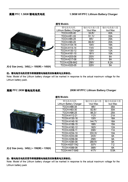
高频PFC 1.5KW 锂电池充电机 1.5KW HF/PFC Lithium Battery Charger型号Models尺寸Size (mm):348(L) × 180(W) × 140(H)注:锂电池充电机的型号将根据锂电池组的实际最高电压来标注。
Note: Model of the Lithium battery charger will be marked in response to the actual maximum voltage for the Lithium battery pack.高频PFC 2KW 锂电池充电机 2KW HF/PFC Lithium Battery Charger型号Models尺寸Size (mm):349(L) × 198(W) × 139(H)注:锂电池充电机的型号将根据锂电池组的实际最高电压来标注。
Note: Model of the Lithium battery charger will be marked in response to the actual maximum voltage for the Lithium battery pack锂电池充电机Lithium Battery Charger输出电压最大值 Vout Max 输出电流最大值Iout Max TCCH-H35-40 34.6V 40A TCCH-H51-33 51.1V 33A TCCH-H65-25 65V 25A TCCH-H90-20 89.8V 20A TCCH-H104-16 104V 16A TCCH-H114-14 114V 14A TCCH-H130-12 130V 12A TCCH-H161-10161V 10A TCCH-H203-08203V 8A TCCH-H217-08217V 8A TCCH-H258-6A2 258V 6.2A TCCH-H320-05320V 5A锂电池充电机 Lithium Battery Charger 输出电压最大值 Vout Max输出电流最大值Iout Max TCCH-H66-35 66V 35A TCCH-H83-30 82.6V 30A TCCH-H96-25 96.2V 25A TCCH-H112-21 112V 21A TCCH-H130-18 130V 18A TCCH-H145-16 144.7V 16A TCCH-H168-15 168V 15A TCCH-H192-12 192V 12A TCCH-H208-11 208V 11A TCCH-H234-10 233.3V 10A TCCH-H243-09 243V 9A TCCH-H258-09 258V 9A TCCH-H290-08 289.5V 8A TCCH-H337-7A2 337V 7.2 TCCH-H389-06 389V 6A TCCH-H417-5A5 417V5.5A高频PFC 3KW 锂电池充电机 3KW HF/PFC Lithium Battery Charger型号Models尺寸size (mm):257(L) × 254(W) × 179(H)注:锂电池充电机的型号将根据锂电池组的实际最高电压来标注。
AA Portable Power CH-PFC1215 电池充电器说明书

AA Portable Power Corp,Email:**********************User Manual for CH-PFC12151. OverviewThe CH-PFC1215 charger is suitable for charging lithium ion battery packs such as those used in electric vehicle applications. The CH-PFC1215 charger is designed to work seamlessly with Battery Management System (BMS) through the CAN interface or digital input for safe battery charging. Standard safety features include protection against a short circuit on the charger output, reverse polarity, over charging, over temperature, etc.2.Technical Parameters2.1Specifications•Model: CH-PFC1215, for 4 cells pack,•Input Voltage: 96 to 260 VAC•Max. Output Voltage: 14.2V (3.55V/cell)•Maximum Output: 15A•Power factor: ≥99%•Efficiency: ≥92%•Input voltage range: AC 85 ~ 242V•Frequency range: 45 ~ 65Hz•Communication: CAN and 12V Digital Input2.1Operating Environment•Altitude: ≤2000 Meters•Temperature: -35°C ~ 65°C•Storage environment: -40°C ~ 100°C – Keep away from combustible materials •Vibration: SAEJ1378•Water resistance: IP31•Installation Stress: ≤ l evel 5•Humidity: 5% ~ 70% RH – Non Condensing, keep away from exposure to moisture 3.Charging Status and Alarm Status Indication3.1 1 Alarm Indication•Reverse polarity or low voltage: light blinking, 20% light on•Charger over heating: light blinking, 40% light on•Ambient temperature too high: light blinking, 60% light on•Charging time out: light blinking, 80% light on•Over Voltage Protection: light blinking, 100% lights on•BMS alarm/charging interruptions All LED’s blinking3.2Charging Status Indication•Shutdown status: Six lights blinking•Charging stage: Percent light indicating pack voltage vs. max charging - voltage•Battery presence not detected: Red light blinking, 20% light on•Charging complete: All green lights on4.Functions4.1Output short circuit protection.4.2Over-temperature protection:Temperature less than 85°C – Full charging powerTemperature is 85°C to 95°C – Power reduced to 50%Temperature is greater than 95°C – No output4.3Reverse polarity protection: charger will not turn on if the battery pack is connected backwards (or less than 5V).4.44 A switch on the charger marked “Override” is used to select either external or internal controlled charging.Override Off – Use with BMS system, either CAN or digital inputOverride On – Charger program based on pack voltage only (recommended for testingpurposes only, do not use for normal charging).4.5When external control is selected and a CAN signal is used, if any cell reaches the recharge set point (default 3.7V as signaled by the BMS) the charger will automatically enter the final recharge cycles.4.6Recharge cycles. When the BMS detects any cell has reached the recharge set point (default 3.7V) or above, the charger reduces the charge current to zero amps for five minutes to allow the BMS to balance the battery pack. The charge will resume after five minutes at half the previous charge current and will again charge until it receives a signal from the BMS that a cell has reached the recharge set point. These recharge cycles continue until the charging current reaches the minimum charging current to complete the charging process.4.7Digital alarm input:0.0V – 2.0V: Charging stopped2.5V – 12.0V: Enable charging or resume charging4.8When both CAN and the digital control signals are available the charger is controlled by theCAN communication signal.5.Connections5.1Anderson SB50 Connector for output. These connectors are labeled “+” and “-“. A matingconnector comes with the charger.-+5.2CAN and Digital Input ControlsA five wire connector connects to the charger for interfacing with the BMS. Three wires have a white connector attached, these three wires are the CAN interface. The other two wires are labeled “+ 12V” and “- 12V”, these wires are the digital input used to control the charger from the BMS CPU. Connect the “+ 12V” to the OV connection on the BMS CPU and the “- 12V” to the GND connection on the BMS CPU.The BMS CPU will output a 12 volt signal from the “OV” terminal whenever a pack normal situation is detected. During charging if a cell exceeds the maximum voltage limit this will drop to 0 volts which will trigger the charger to temporarily pause charging until the high voltage cell can return to a normal voltage. All green LED’s on the charger will flash when this occurs.For a CAN communication connection connect the CANH, CANL and CAN GND to the matching connection on the CAN connection on the BMS CPU. The white connector may be cut off of the cable; however, note which wires are which before doing so.CANHCANLCAN GNDIf both the CAN communication and the digital inputs are connected CAN communicationswill take priority over the digital input for charge control. CAN communications requires the optional CAN board be installed on the BMS CPU.*Caution* The BMS CPU has a programming port on it marked “Rx, Tx, RES, VSS”. Do not attempt connect the CAN communication connection to this port!6.Cautions•Make sure charger voltage output matches to the number of cells in the battery pack.•Make sure positive output of the chargers is connected to a positive connection to the battery pack, and the negative output of the charger is connected to a negativeconnection of the battery pack.•After a complete charge, disconnect the power source from the charger and then disconnect the connection between the charger and the battery pack.• A BMS system must be used during the charging process either through CAN communication or through the digital alarm input to prevent over-charging.7.Troubleshooting•The charger must be installed in a cool well-ventilated area which is free of dust•If the charger is not charging unplug the charger from the AC line and battery pack, then check for poor connections, short circuits, over heating conditions as well as alarm status from the Energy Management System.•If charger does not display any LED’s when plugged in and charging does not occur the fuse may be blow. Unplug the charger from the battery pack and AC line and check the fuse by unscrewing the cap with a #2 Philips screw driver. If the fuse is blown replace with an equivalent size fuse of the same voltage and amperage rating.•If the charger finishes charging too early make sure that the connection from the charge to the battery pack is good and does not have high resistance.。
15KW-750电动汽车充电器培训资料

≤0.5%
380VAC额定输入电压,额 定输出电压。 100%负载>95%
30%~70%负载>95%
峰值效率>96%
安装方式 重量
冷却模式 防护等级
机架式 ≤12kg
智能风冷,温控调 速 IP32
通讯接口
显示 可并联台数
隔离RS485, CAN2.0B
LED 不限(推荐为20台)
输出功率特性
323VAC~437VAC输入电压条件 -20℃~50℃ :15000W输出100%额定功率 50℃~60℃ :50℃开始从100%线性降额,60℃降额到50%额定功率 60℃以上,模块过温保护。
图3-1前面板指示
面板上指示灯:
电源指示灯
绿灯 1个;
告警灯
黄灯 1个;
故障指示灯
红灯 1个;
负载状态指示灯 绿灯 8个。
模块保护告警时告警指示灯亮,模块故障告警时故障指示灯亮。
负载状态灯用来表示输出电流的大小。
• 风扇调速控制:
模块将根据检测的温度和负载进行风扇调速,可通过系统监控设置为满转。
• 风扇故障保护:
冲击
-40℃~70℃
-40℃~70℃
模块应能承受频率 为10Hz~55Hz,振幅 为 0.35mm 的 正 弦 波 振动 整流模块能承受峰 值加速度为 150m/S^2 , 持 续 时 间为11ms 的冲击
软启动时间
3s≤time≤10s
功率因数PF (25℃,额定输入 电压380VAC,要
求电压源 VTHD<1.1%)
充电器拓扑结构框图
技术路线
有源数字化维也纳PFC电路设计 在三相整流器中,多采用三电平PWM整流器来减少
充电机安装技术规范
充电机安装技术规范
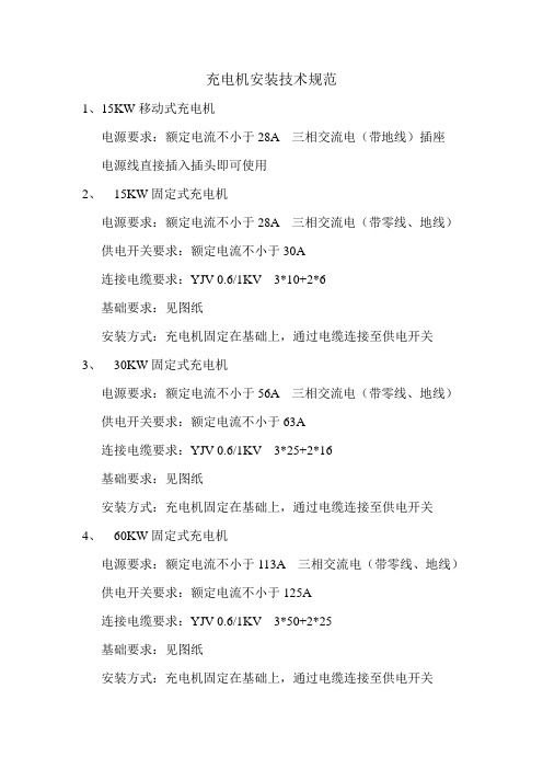
1、15KW移动式充电机
电源要求:额定电流不小于28A 三相交流电(带地线)插座电源线直接插入插头即可使用
2、15KW固定式充电机
电源要求:额定电流不小于28A 三相交流电(带零线、地线)供电开关要求:额定电流不小于30A
连接电缆要求:YJV 0.6/1KV 3*10+2*6
基础要求:见图纸
安装方式:充电机固定在基础上,通过电缆连接至供电开关
3、30KW固定式充电机
电源要求:额定电流不小于56A 三相交流电(带零线、地线)供电开关要求:额定电流不小于63A
连接电缆要求:YJV 0.6/1KV 3*25+2*16
基础要求:见图纸
安装方式:充电机固定在基础上,通过电缆连接至供电开关
4、60KW固定式充电机
电源要求:额定电流不小于113A 三相交流电(带零线、地线)供电开关要求:额定电流不小于125A
连接电缆要求:YJV 0.6/1KV 3*50+2*25
基础要求:见图纸
安装方式:充电机固定在基础上,通过电缆连接至供电开关。
- 1、下载文档前请自行甄别文档内容的完整性,平台不提供额外的编辑、内容补充、找答案等附加服务。
- 2、"仅部分预览"的文档,不可在线预览部分如存在完整性等问题,可反馈申请退款(可完整预览的文档不适用该条件!)。
- 3、如文档侵犯您的权益,请联系客服反馈,我们会尽快为您处理(人工客服工作时间:9:00-18:30)。
15KW电动汽车充电机一体机
充电一体机选择表:
甲方在本协议中向乙方明确以下选择设备清单:
(1) 直流充电一体机基本参数
充电机额定功率:15 KW;输出直流电压:500 V;输出直流电流:30 A;
(2) 充电枪线长选择
充电枪线长:√5M □6M □8M □其他M;
(3) BMS供电电源功率选择
辅助电源:□500W 24V/20A √150W 12V12A;□其他型号;
充电一体机主要技术指标:
⏹额定功率:15KW
⏹输入电压:AC380V±15%;
⏹输入模式:三相五线制;
⏹输入电流:40A
⏹工作频率:45~65Hz;
⏹输出电压范围选择:√低压DC 200V~500V □高压DC 200V~750V(当输出电压低于DC350V,
充电机各项指标性能降低);
⏹输出电流范围选择:√低压(0A~30A)□高压(0A~15A)
⏹输出电压误差:≤0.5%
⏹输出电流误差:小于30A时≤0.3A;大于等于30A时≤1%
⏹满载效率:≥93%;
⏹输入功率因数:≥0.99;
⏹THD (总谐波电流含量):≤5% 在50%-100%负载时
⏹平均无故障时间(MTBF):≥8760小时;
通用功能
a) 恒流恒压充电功能:适用于对车载高压铁锂电池系统进行充电,输出直流电压能够有效调整,输出电
流能够有效调整。
b) 充电机能和电池管理系统CAN通信,接收电池管理系统的控制命令数据,可实时改变充电电流,
且当电池管理系统发出异常信息后应能自动停止充电。
c) 充电机具有面板操作功能,操作界面使用图形化的触摸屏,可以详细显示各个模块的工作状态。
d) 充电方式有两种,BMS充电方式和手动充电方式。
BMS充电方式使用CAN现场总线与电池管理
系统BMS实时通信,对动力锂电池的快速充电进行优化和可靠的保护。
e) 外装有急停按键及运行指示灯,能够实时显示充电状态。
f) 充电机具有输入欠压、输入过压、输出短路、限流、输出过压、过流、反接、通讯故障、报警等
保护预警功能。
g) 配置有单充高压大电流国标充电枪,能够有效保证充电安全。
h) 充电机能够确保室外环境正常使用,防护级别高。
i) 充电机具有提供低压直流辅助电源功能,工作要求符合国标《GBT27930-2011电动汽车非车载传
导式充电机与电池管理系统之间的通讯协议》。
工作环境条件
⏹工作环境温度:-40℃~+50℃(在+40℃~+50℃高温可限功率使用)
⏹储存和运输温度:-40℃~+85℃
⏹大气压力:80 kPa ~110 kPa(海拔2000m及以上降功率使用)。
结构要求
⏹壳体可采用落地式安装方式;
⏹整体无外露锐角,表面涂覆色泽层应均匀光洁,不起泡、不龟裂、不脱落;
⏹外壳应有密封、防尘、防潮、防水性能,并具有一定的强度;
⏹非绝缘材料外壳应可靠接地;
⏹具有防止人员轻易触及带电部件的结构功能;
⏹操作按键和显示界面应设置在便于人操作和查看的位置
⏹防护等级: IP54。
充电流程图
充电系统装备清单:
1. 15KW直流充电桩:(输入AC380V输出DC 200V~500V 30A BMS供电电源
150W 12V12A具体通讯协议由BMS厂家提供)1台。
2. 电池组:(DC200V~500V,30~100AH锂电池组)1组。
3. 电池:12V20AH铅酸免维护电池1个。
4. BMS系统:(根据锂电池组串数由电池组厂家提供具体参数要求)。