therm作业指导书
热压作业指导书
热压作业指导书一、背景介绍热压作业是一种常见的工艺操作,用于将两个或多个材料通过高温和高压的作用进行粘合或加固。
本指导书旨在为操作人员提供详细的操作步骤和注意事项,确保热压作业过程安全、高效。
二、操作流程1. 准备工作a. 确保操作区域整洁有序,清除杂物和可燃物。
b. 检查热压设备的状态,确保其正常工作。
c. 确认所需材料和工具齐全。
2. 材料准备a. 根据工艺要求,准备所需的材料。
b. 对材料进行清洁处理,确保表面干净无污染。
c. 检查材料尺寸和数量是否符合要求。
3. 设备设置a. 打开热压设备的电源,预热设备至工艺要求的温度。
b. 根据工艺要求,调整热压设备的压力。
c. 确保热压设备的温度和压力稳定。
4. 材料定位a. 将待加工的材料放置在热压设备的工作台上。
b. 根据工艺要求,调整材料的位置和角度。
c. 使用夹具或定位装置固定材料,确保其不会移动或变形。
5. 热压操作a. 将定位好的材料放入热压设备中。
b. 关闭热压设备的安全门,确保操作人员安全。
c. 按下开始按钮,启动热压设备的压力和温度控制系统。
d. 根据工艺要求,设定热压时间。
e. 等待热压时间结束,热压设备会自动停止。
6. 检查和清理a. 打开热压设备的安全门,取出热压后的材料。
b. 检查材料的粘合情况,确保达到要求。
c. 清理热压设备,清除残留材料和污垢。
d. 关闭热压设备的电源,确保设备安全关闭。
三、注意事项1. 操作人员必须经过专业培训,熟悉热压作业的操作流程和安全规范。
2. 操作人员应佩戴适当的个人防护装备,如安全眼镜、耳塞、手套等。
3. 在进行热压作业前,必须对设备进行检查和维护,确保设备处于良好状态。
4. 操作人员应严格按照工艺要求进行操作,不得随意调整热压设备的参数。
5. 在热压过程中,操作人员应保持警惕,注意观察设备的运行状态,如有异常应立即停机检查。
6. 热压作业结束后,操作人员应及时清理设备和工作区域,确保环境整洁。
Cres Cor 12kW QuikTherm Retherm 炉子操作说明书
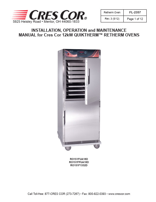
5925 Heisley Road • Mentor, OH 44060-1833INSTALLATION, OPERATION and MAINTENANCEMANUAL for Cres Cor 12kW QUIKTHERM™ RETHERM OVENSRetherm OvenFL-2357Rev. 3 (5/12)Page 1 of 12RO151FUA18D RO151FPUA18D RO151F1332D5925 Heisley Road • Mentor, OH 44060-1833Retherm Oven FL-2357Rev. 3 (5/12)Page 2 of 12TABLE OF CONTENTSSUBJECT PAGEINSTALLATION INSTRUCTIONS . . . . . . . . . . . . . . . . . . . . . . . . . . . . . . . . . . . . . . . . . . . . .3OPERATING INSTRUCTIONS First Time Operation . . . . . . . . . . . . . . . . . . . . . . . . . . . . . . . . . . . . . . . . . . . . . . . . . . . .3 How to Use Control for Cooking & Holding . . . . . . . . . . . . . . . . . . . . . . . . . . . . . . . . .4 How to Save and Use Recipes . . . . . . . . . . . . . . . . . . . . . . . . . . . . . . . . . . . . . . . . . . . .5 “Quick Recipe” and Other Menu settings . . . . . . . . . . . . . . . . . . . . . . . . . . . . . . . . . . . .5MAINTENANCE INSTRUCTIONS How to Clean the Unit . . . . . . . . . . . . . . . . . . . . . . . . . . . . . . . . . . . . . . . . . . . . . . . . . .6 Trouble Shooting Guide . . . . . . . . . . . . . . . . . . . . . . . . . . . . . . . . . . . . . . . . . . . . . . .7, 8 Cabinet Replacement Parts . . . . . . . . . . . . . . . . . . . . . . . . . . . . . . . . . . . . . . . . . . . . . . .9 Hot Unit Replacement Parts . . . . . . . . . . . . . . . . . . . . . . . . . . . . . . . . . . . . . . . . . . . . .10 Wiring Diagram For 208/240 V olt, 3 Phase . . . . . . . . . . . . . . . . . . . . . . . . . . . . . . . . .11 Wiring Diagram for 480 V olt, 3 Phase . . . . . . . . . . . . . . . . . . . . . . . . . . . . . . . . . . . .12SERVICE POLICY and AGENCY LIST . . . . . . . . . . . . . . . . . . . . . . . . . . . . . . . . . . . .FL-14005925 Heisley Road • Mentor, OH 44060-1833Retherm OvenFL-2357Rev. 3 (5/12)Page 3 of 12HOW TO INSTALL CABINETS:1 . Remove all packing material from inside and outside of cabinet .2 . Position cabinet on level floor; install the cabinet interior (pan slides) if not already installed .3 . Plug power cord into proper wall receptacle .INSTALLATION INSTRUCTIONSVENTING YOUR OVEN:1 . The purpose of ventilating hoods is to direct and capture smoke, grease-laden vapors, heat, odors, or fumes .2 . Low temperature equipment (maximum temperature 250°F/121°C) does not produce heat, odors, fumes, grease-laden vapors or smoke and is not required to be vented .3 . Most jurisdictions consider our low-temperature ovens (maximum temperature is 350°F/177°C) as low-heat appliances not requiring vent hoods .4 . Installation must conform with local codes . The authority having jurisdiction of enforcement of the codes will have the responsibility for making interpretations of the rules .UNIT SPECIFICATIONS: All units use six (6) elements (2000 watts each) . All units are rated 12000 watts .MODEL NOS.ELECTRICAL SPECS(AC SERVICE)ELEC. LOADPOWER SUPPLY REQUIREMENT ALL 3 PHASE IS 3 WIRE + GROUNDVOLTSPHASESHZAMPSVOLTSAMPSPHASESVOLTSRECEPTACLERO151FUA18D2083RO151FPUA18D2083RO151F1332D20832083603420850320815-50R RO151FUA18D2403RO151FPUA18D2403RO151F1332D24032403602924050324015-50R RO151F1332D480348036015480303480L16-30RFIRST-TIME OPERATIONNOTE: A new oven needs to “burn off” manufacturingoils and excessive adhesive before its first use. Do NOT load food into oven until this has been done!1 . Push the switch to on; the light will come on.NOTE: The letters “LOTPR” (low temperature) will showon the control panel until it reaches 140°F (60°C) .2 . Press the “COOK” button .3 . Push down and turn the control knob to show 200°F . Push the knob again to set the temperature . Run the unit for one (1) hour . 4 . Turn the unit off and let cool .5 . Wipe the inside clean with detergent and hot water .HOW TO CHANGE FROM °C TO °F (if needed)1 . Push the switch on; the light will come on.2 . Push and hold the “SET” button and the button in the lower left hand corner together for 5 seconds .You are now entered into the menu .3 . Scroll over the”Unit” and change it to “C” , then scrollto the “END” .5925 Heisley Road • Mentor, OH 44060-1833Retherm Oven FL-2357Rev. 3 (5/12)Page 4 of 12OPERATING INSTRUCTIONSHOW TO USE THE RETHERM CONTROL:*Push the lighted switch on the control panel; the light will come on and the cabinet will start heating .*The display will read “LOTPR” (low temperature) below 140°F . (60°C .) .NOTE: Wait one (1) hour after start up before loading thefood for best results . The display will read “PREHT” until the cabinet reaches the set temperature .Cooking:1 . Press the COOK button .2 . Turn the control knob to the desired cookingtemperature between 200°F (93°C) and 350°F (176°C) .3 . Push the knob to set the temperature .4 . The control automatically goes to the HOLD mode . (Continue to step 1 below) .Holding:(Press the HOLD button only if you are just holding food),1 . Turn the control knob to the desired holdingtemperature between 140°F (60°C) and 220°F (104°C) .2 . Push the knob to set the temperature .3 . The control automatically goes to the TIME mode .Setting the time or Food Probe:1 . If NOT using the Food Probe:a) Turn the control knob to the desired hours/minutes . b) Push the knob to set the time .2 . Using the Food Probe:Plug in the food probe BEFORE you enter the TIME mode . Otherwise, you have to press the PROBE button to set the probe temperature .a) Turn the knob to the desired temperature .b) The timer will stop when the probe reaches the set temperature .3 . Press the START button . The display will show “READY” when preheated .4 . Press the START again to use this recipe (see Recipes”) .Note: Press the knob for 4 seconds to cancel the recipe .The DISPLAY button shows (cycles through) all the values when in each mode:• “PREHEAT” OR “READY”: momentarily shows theactual cabinet temperature .• “COOK” (Timed): shows Home screen, set point,count down time, actual cabinet temperature .• “COOK” (Probe): shows Home screen, set point,count up time, actual cabinet temperature .• “HOLD”: shows Home screen, set point, count uptime, actual cabinet temperature .AIR RETHERM SWITCHThis switch MUST be pushed to “HIGH” (ON) for Retherming food .RECIPES:The control can hold up to 18 saved recipes .To save a recipe:1 . Press and hold both the TIME button and the knobfor 5 seconds. The screen will be flashing. This is the setup menu .2 . Turn the knob through the menu until you get to“Edit” .3 . Press the knob and turn to the recipe you want to edit .There are 18 blank recipes to customize and save .4 . Press the knob and enter the cook, hold and timevalues .5 . After the entering the final value, “Edit” will showagain .6 . Press the knob to edit more recipes or turn to “End” toexit the menu .To use one of the recipes:1 . Push one of the three RECIPE group buttons for therecipe number you want .2 . Turn the knob to the recipe you want and press theknob to select .3 . Press the START button to preheat .4 . After it shows “READY”, press the START buttonagain to begin the recipe .Note: The display button will cycle through all the values as before, but will include the recipe number, ifusing a saved recipe .Quick Recipe Note:You can set “Quick Recipes” for recipes that you use often . This way, when you press a recipe group button and press start, that recipe will start cooking without searching for the recipe number . Recipe numbers can be set up as “quick recipes” as follows:1 . Press and hold both the TIME button and the knob for5 seconds to get into the menu .2 . Turn the knob to “RBTN” and press the knob . Theword “PUSH” will flash.3 . Press one of the recipe group buttons to assign arecipe .Note: Recipe numbers 1-6 can be set up as Group button 1 .Recipe numbers 7-12 can be set up as Group button 2 .Recipe numbers 13-18 can be set up as Group button 3 .4 . Turn the knob to the recipe number you want to assignto that button and press the knob .Repeat the process to assign recipes to the other two recipe group buttons; or,turn the knob to “END” the submenu; turn to “END” themenu .Additional Menu Settings:Press and hold both the TIME button and the knob for 5seconds to get into the menu .Here you can set the recipes, quick recipes, temperatureunits (°C or °F) and the datalogsettings (USB connection required):”RECE” allows you to enable or disable the data recordfeature .“RECF” allows you set how often (in minutes) adatapoint will be recorded .“RECD” allows you to set how long (in days) youwould like the data to be stored in memory . OPERATING INSTRUCTIONS (continued)HOW TO CLEAN THE UNIT:SOIL CLEANER METHODCABINET Inside and Outside (Stainless Steel)ROUTINE CLEANINGSoap, ammonia or milddetergent* and water.1. Sponge on with cloth2. RinseSTUBBORN SPOTS,STAINSMild abrasive made forStainless Steel.1. Apply with damp sponge or cloth.2. Rub lightly.BURNT ON FOODS ORGREASEChemical oven cleanermade for Stainless Steel.Follow oven cleaner manufacturer’sdirections.HARD WATER SPOTS &SCALEVinegar1. Swab or wipe with cloth.2. Rinse and dry.* Mild detergents include soaps and non-abrasive cleanersMAINTENANCE INSTRUCTIONSHOW TO CLEAN THE UNIT1. Unplug cord from wall. Allow cabinet tocool.2. Do NOT hose cabinet with water.3. Do NOT get water on controls.4. Do NOT use abrasives or harshchemicals.5. Do NOT use “Cres Clean” (or any citruscleaner) on labels or plastic parts. BEFORE cleaning the cabinet:Cleaning Hints:1 . Use the mildest cleaning procedure that will do thejob .2 . Always rub in the direction of the polish lines to avoidscratching the surface .3 . Use only a soft cloth, sponge, fibrous brushes, plastic or stainless steel pad for cleaning and scouring .4 . Rinse thoroughly with fresh water after every cleaning operation .5 . Always wipe dry to avoid water marks .5925 Heisley Road • Mentor, OH 44060-1833Retherm Oven FL-2357Rev. 3 (5/12)Page 7 of 12MAINTENANCE INSTRUCTIONSTROUBLE-SHOOTING GUIDE, continuedHOW TO ADJUST THE DOOR LATCH:1 . For vertical (up and down movement) adjustment:a . Loosen (2) screws located in magnetic strike .b . Move strike up or down for alignment to magnet on latch .c . Tighten screws to secure 2 . For horizontal (greater or lesser magnetic draw) adjustment:a . Loosen (4) screws in door latch .b . Move latch forward or backward to adjust magnetism .c . Tighten screws to secure .IF OVEN GETS TOO HOT OR WON’T SHUT OFF, DISCONNECTPOWER AT BRANCH PANEL. DO NOT UNPLUG CORD!TROUBLE-SHOOTING GUIDE1 . Cord is unplugged from wall outlet .2 . Circuit breaker/fuse to wall outlet is blown .3 . Switch is turned off .4 . Fuse on back of unit is blown .If unit is NOT working, first check the following causes:PROBLEMPOSSIBLE CAUSE SOLUTION Oven does not turn on1. Power switch is bad2. Retherm control is bad.1. Replace2. Replace5925 Heisley Road • Mentor, OH 44060-1833Retherm Oven FL-2357 Rev. 3 (5/12)Page 8 of 12IF THE OVEN TURNS ON:PROBLEM POSSIBLE CAUSE SOLUTIONOven does not heat, or doesn’t heat properly 1. Sensor2. Heater contactor3. Loose wiring at heater contactor4. Retherm control5. High Limit1. Replace2. Replace3. Replace4. Replace5. ReplaceBlowers do not operate 1. Air retherm switch2. Blower3. Retherm control1. Replace2. Replace3. ReplaceHeater will not shut off 1. Control defective2. Heater contactor1. Replace2. ReplaceVent fans do not shut off 1. Vent fan switch defective2. Control compartment is still hot.1. Replace2. Wait until it coolsCheck “Heater will not shut off”Vent fans do not operate (See Note)1. Vent fan switch defective2. Vent fan defective1. Replace2. ReplaceControl will not switch from “COOK” to “HOLD” (timed mode)1. Oven is in “PROBE” mode.2. Retherm control defective1. Cancel recipe and switch to “TIMED” mode2. ReplaceControl will not switch from “COOK” to “HOLD” (probe mode)1. Oven is in the “TIMED” mode2. Probe not plugged in3. Probe defective4. Retherm control defective1. Cancel recipe and switch to “PROBE” mode2. Plug in probe3. Replace4. ReplaceControl will not switch to “COOK” (probe mode)1. Oven in “TIMED” mode2. Probe temperature setting lowerthan probe temperature3. Probe not plugged in4. Retherm control defective1. Switch to “PROBE” mode2. Set probe temperature to desired tempera-ture3. Plug in probe4. ReplaceMAINTENANCE INSTRUCTIONSTROUBLE-SHOOTING GUIDE (continued)ERROR CODES:CODE DISPLAYED CAUSE SOLUTIONno p No meat probe Plug in probeErr0Temp probe bad ReplaceNOTE: Vent fans will not operate until the control compartment requires ventilation to limit temperatures . Replacement of electrical components must be done by a qualified electrician.Refer to our Service Agency list, FL-1400 (found in the back of this manual), of authorized service centers .Instructions for replacing parts are included in replacement parts list .5925 Heisley Road • Mentor, OH 44060-1833Retherm Oven FL-2357Rev. 3 (5/12)Page 9 of 12REPLACEMENT PARTSReplacement Parts:ITEM DESCRIPTION PART NUMBER19. Door Assembly (1332D)1221-579-K Door Assembly (UA18D)1221-580-K 20. Door Latch Kit 1006-122-01-K 21. Door Strike Kit 1006-122-02-K 22. Door Hinge Kit0519-109-K 23. Door Gasket (1332D)0861-185-K Door Gasket (UA18D)0861-235-K 24. Casters0569-306-R 25. Casters w/brake 0569-306-B 26. Posts 0696-25027. Air Tunnel0546-146-C 28. Wire Angles (2 per kit)0621-281-SS-K Drip Pan (clear)1017-0585925 Heisley Road • Mentor, OH 44060-1833Retherm OvenFL-2357Rev. 3 (5/12)Page 10 of 12ITEM DESCRIPTION Part No.ITEM DESCRIPTION Part No.1 . Switch (On/Off)0808-12510 . Hi Limit Switch 0848-0772 . Retherm Thermostat 11 . Transformer 0769-197Digital Control 0848-092-0312 . Relay0857-102Sensor0848-09113 . Fan Switch 0848-0343 . Blower Switch 0808-11414 . Power Cord Kit 0810-178-K 4 . Vent Fan 0769-17416 . Strain Relief Kit 0818-103-K 5 . Fan Guard 0769-16717 . Heater Kit (208V)0811-0300-K 6 . Fuse0807-155Heater Kit (240V)0811-0301-K Fuse Holder 0807-150Heater Kit (480V)0811-0302-K Fuse (480V)0807-058Connector, Probe (not shown)0848-094Fuse Holder (480V)0807-048Food Probe 1 .5” Long 0848-0987 . Blower Kit 0769-186-K Food Probe 6” Long 0848-1008 . Contactor0857-0269 . Terminal Block, rear0852-093Electrical Replacement Parts:TOP VIEW WITHOUT COVERREAR VIEWFRONT VIEW5925 Heisley Road • Mentor, OH 44060-1833Call Toll-free: 877-CRES COR (273-7267) • Fax: 800-822-0393 • Retherm OvenFL-2357Rev. 3 (5/12)Page 11 of 12REPLACEMENT PARTSfor NON-PASS THRU OVENS RO151F SERIES 208/240V 3 PhInclude all informationH I G H T E M P I M P O R B L O W c l o s e s @130F5925 Heisley Road • Mentor, OH 44060-1833Call Toll-free: 877-CRES COR (273-7267) • Fax: 800-822-0393 • Retherm OvenFL-2357Rev. 3 (5/12)Page 12 of 12REPLACEMENT PARTSfor OVENS RO151F SERIES 480V, 3 PhInclude all information on nameplate whenH I G H T E M P c l o s e s @130F。
Therm-X-Trol Therm-X-Span产品安装、操作和维护指南说明书

Do not install on domesticwater systems, or in open heating systems. Corrosion and tank failure may result. Use a Therm-X-Trol ® or Therm-X-Span ® for domestic water systems. Use a Solar EXTROL ®for closed-loop solar heating systems.INSTRUCTIONS AND WARNINGS IN THE MANUAL MAY RESULT INSERIOUS OR FATAL INJURY AND/OR PROPERTY DAMAGE, AND WILL VOID THE PRODUCT WARRANTY. THIS PRODUCT MUST BE INSTALLED BY A LICENSED PROFESSIONAL. FOLLOW ALL APPLICABLE LOCAL AND STATE CODES AND REGULATIONS, IN THE ABSENCE OF SUCH CODES, FOLLOW THE CURRENT EDITIONS OF THE NATIONAL PLUMBING CODE AND NATIONALproperty damage. To minimize risk, a licensed professional must installand periodically inspect and service the Product. A drip pan connected toan adequate drain must be installed if leaking or flooding could cause property damage. Do not locate in an area where leaking could causeproperty damage to the area adjacent to the appliance or to lower floors of the structure.Do not240° F (Intermittent); 225° F (Continuous). Do not adjust the pre-charge or re-charge this Product except during installation or regular inspection. Replace the Product and do not adjust the pre-charge if corroded, damaged or with diminished integrity. Adjustments to pre-charge must be done at ambient temperature only. Failure to properly size the Product or follow these instructions may result in excessive strain on the system and may lead to Product failure, seriousor fatal personal injury, leakage, and/or property damage.At least once every 3 years or if discharge is present, a licensed contractor should inspect the pressure relief valve and replace if corrosion is evident or the valve does not function. FAILURE TO INSPECT THIS VALVE AS DIRECTED COULD RESULT IN UNSAFE PRESSURE BUILD-UP WHICH CAN RESULT IN PRODUCT FAILURE,SERIOUS INJURY OR DEATH AND/OR SEVERE PROPERTY The water quality You should test for corrosive elements, acidity, total solids and other relevant contaminants, including chlorine and treat your water appropriately to insure satisfactory performance and preventpremature rmation go to .NOTE: Inspect for shipping damage. Notify freight carrier or store where purchased immediately if damage is present. To avoid risk of personal injury and property damage, if the product appears to be malfunctioning, shows signs of corrosion, or if indicator cap is discolored, call a licensed professional immediately. Current copies of the product manual can be viewed at . Use proper safety equipment when installing.THIS IS THE SAFETY ALERT SYMBOL. IT IS USED TO ALERT YOU TO POTENTIAL PERSONAL INJURY AND OTHER HAZARDS. OBEY ALL SAFETY MESSAGES THAT FOLLOW THIS SYMBOL TO REDUCE THE RISK OF PERSONAL INJURY AS WELL AS PROPERTY DAMAGE.Models SE-15, SE-30, SE-60For Use In Closed-Loop Solar Heating Systems OnlySOLAR EXTROL ® is designed for use in a closed-loop solar heating systems with a maximum operating temperature of 250° F (Intermittent); 225° F (Continuous).Pre-Installation1. Visually inspect for any damage. Ensure expansion tank is sized properly for the application (Figure 1).2. With tank empty of fluid, remove plastic cap from air stem (Figure 2).3. Adjust air precharge to match the system fill pressure. Unit is shipped at 25 PSIG.4. Replace cap and tighten snugly, ensuring the cap is flush against thetank surface.Installation1. Drain the solar system or isolate the area where the Solar Extrol will be installed.3. Once the Solar Extrol is installed, re-pressurize the system and check for leaks. Repair as necessary.4. Restart the system and check for relief valve discharge. If the relief valve drips, the tank may be improperly charged or undersized.5. The Solar Extrol is now operational and will absorb expanded fluid during system operation.Operation1. The Solar Extrol is installed on the supply-side of the solar system. Its sealed-in air pre-charge prevents fluid from entering the tank until the system pressure begins to rise.2. As the water temperature rises, fluid enters the Solar Extrol.3. As the system cools, the diaphragm is forced downward. Fluid is expelled from the Solar Extrol, back into the system.NOTE:Although the Solar Extrol does not have to be installed at the base of an air purger, this installation is recommended to reduce air in the system and provide a compact installation. Some method of air elimination is required to reduce entrained air.MaintenanceA licensed professional should check the complete system, including the expansion tank, yearly and more frequently as the system ages. Checking the precharge allows a small quantity of air to escape and can result in an insufficient air charge. Always check the precharge while the tank is isolated and empty of fluid, and be sure to maintain the proper precharge whenever the tank is inspected. Monitor the tip of the service indicator cap for discoloration (Figure 4) in addition to regular product inspection. Contact the installer or a licensed professional if indicator cap is discolored; tank replacement required. Do not rely on cap as sole indication of tank condition.WarrantySE Models: Five (5) Year Limited WarrantyVisit for complete warranty details.PLEASE READ THE FOLLOWING INSTRUCTIONS CAREFULLYIMPORTANT GENERAL SAFETY INFORMATION -ADDITIONAL SPECIFIC SAFETY ALERTS APPEAR IN THE FOLLOWING INSTRUCTIONS.© 2019 Worthington Industries Inc.Part #: 9015-839 (01/19)One or more features of this product are covered by U.S. patents, visit /patents for more information.1400 Division Road, West Warwick, RI USA 02893T: 800.426.8765。
热压作业指导书

热压作业指导书一、引言热压作业是一种常见的制造工艺,广泛应用于金属加工、电子制造、塑料成型等领域。
本指导书旨在提供详细的操作步骤和注意事项,以确保热压作业的安全性和质量。
二、作业准备1. 确认热压机的规格和性能,包括最大压力、温度控制范围等。
2. 准备所需材料和工具,如热压模具、工件、保护垫片、温度计、压力计等。
3. 检查热压机的工作状态,确保其正常运行,包括电源连接、润滑油状态、机械部件的运转等。
三、操作步骤1. 将热压模具安装到热压机上,确保其牢固稳定。
2. 根据工件的形状和尺寸选择合适的模具,并将工件放置在模具中心位置。
3. 在工件上放置保护垫片,以防止工件表面受损。
4. 根据工艺要求,设置热压机的压力和温度参数。
确保参数的设定符合工艺规范。
5. 打开热压机的电源,并启动预热程序,使热压机达到设定温度。
6. 当热压机达到设定温度后,将工件放置在模具中,并关闭热压机的模具。
7. 启动热压机的压力系统,逐渐增加压力,直至达到设定压力。
8. 维持设定压力和温度一段时间,以保证工件充分热压。
9. 在热压结束后,逐渐减小压力,待压力降至零后,打开模具,取出热压后的工件。
10. 对热压后的工件进行质量检查,包括尺寸、形状、表面质量等指标。
四、注意事项1. 在操作过程中,严禁将手部或其他身体部位放置在热压模具的活动部件附近,以免发生意外伤害。
2. 在热压作业过程中,应佩戴防护手套、护目镜等个人防护装备,确保人身安全。
3. 在设定热压参数时,应根据工艺要求和材料特性进行合理选择,避免温度过高或压力过大导致工件变形或破损。
4. 在热压机运行过程中,应定期检查润滑油的状态,确保热压机的正常运转。
5. 在热压结束后,应及时清理模具和热压机,以确保下次作业的顺利进行。
五、总结热压作业是一项重要的制造工艺,通过本指导书的操作步骤和注意事项,可以确保热压作业的安全性和质量。
在实际操作中,应严格按照工艺规范和操作要求进行,同时注意个人防护和设备维护,以保证作业的顺利进行。
热压作业指导书
热压作业指导书一、任务描述热压作业指导书是为了确保热压作业过程中的安全和质量,提供详细的操作指导和注意事项,以便操作人员正确进行热压作业。
本指导书适用于热压作业过程中的各个环节,包括设备准备、操作步骤、安全注意事项等。
二、设备准备1. 确保热压设备处于正常工作状态,检查设备的温度控制系统、压力控制系统、安全阀等,并进行必要的维护和保养。
2. 准备所需的热压模具、工件、材料等,并进行必要的清洁和检查,确保其符合要求。
3. 检查热压设备的环境条件,包括温度、湿度等,确保符合热压作业的要求。
三、操作步骤1. 确保操作人员已经接受过相关的培训,了解热压作业的操作要求和安全注意事项。
2. 将工件放置在热压模具中,并根据工件的形状和尺寸进行调整,确保工件能够均匀受力。
3. 调整热压设备的温度和压力,根据工艺要求进行设定,并确保设备能够稳定运行。
4. 将热压模具放置在热压设备中,并进行必要的固定和对位,以确保模具和设备之间的配合良好。
5. 启动热压设备,开始进行热压作业。
在热压过程中,要注意观察设备的运行情况,确保温度和压力的稳定。
6. 热压作业完成后,停止热压设备的运行,并进行冷却处理。
冷却过程中,要注意避免突然降温引起的热应力。
7. 将热压模具从设备中取出,并进行必要的清洁和维护,以便下次使用。
四、安全注意事项1. 操作人员必须穿戴符合要求的个人防护装备,包括防护眼镜、防护手套、防护服等。
2. 在热压作业过程中,严禁将手部或其他身体部位靠近热压设备,以免发生烫伤事故。
3. 在热压设备运行过程中,严禁随意调整温度和压力,以免造成设备故障或工件损坏。
4. 热压设备周围必须保持清洁和整洁,防止杂物堆积引发安全事故。
5. 在热压作业过程中,操作人员应密切关注设备的运行情况,如发现异常情况应及时停机检查。
6. 热压作业完成后,要及时清理工作现场,确保设备和周围环境的整洁。
五、总结本热压作业指导书详细介绍了热压作业的设备准备、操作步骤和安全注意事项。
ThermCal130 热 blocked温度校准器操作手册说明书

ThermCal130Dry Block Temperature CalibratorINSTRUCTION MANUALPlease read all the information in this booklet before using the unit. January 2015Rev 1.0The ThermCal130IntroductionThe ThermCal130 calibrator provides a safe, dry, constant temperature source for checking and calibrating a wide range of temperature sensors, systems, indicators and thermometers. It is fast and economical and can be used either on a bench top or as a portable field unit. The weight of the unit is only 17 pounds/7.7 kilograms. The unit covers the temperature range from -20°C to +130°C in an ambient of 20°C using a machined aluminum block as the heat transfer medium. The temperature control circuit is built into the unit.Features include:• Maximum temperature of 130°C/266°F• Minimum temperature of -20°C/-4°F• Up to eight setpoints can be stored & recalled• insert well & ¼” diameter reference wellEven though the unit heats up and cools down rapidly, highly efficient insulation and an internal cooling fan ensures that the case remains safe enough to handle even at maximum operating temperatures. The ThermCal130 calibrator has been designed to comply with all relevant electromagnetic interference and electrical safety regulations.-1-SpecificationFigures quoted are at the base of the well at the time of calibration.Temperature range: -20°C/-4°F to 130°C/266°F at an ambient of 20°C/68°FNOTE: the typical minimum achievable temperature is 40°C/72°F below the room ambient temperature Display resolution: 0.1°Accuracy: ±0.4°C (-20 to 130°C)±0.8°C (-4 to 266°F)Stability (10 minutes): ±0.050°C(10 minutes after reaching setpoint) ±0.060°CHeat up time -20 to 130°C: 9 minutesHeat up time 20 to 100°C: 4 minutesCool down 20 to -20°C: 9 minutes (ambient of +20°C)Cool down 130 to 20°C: 4 minutesImmersion Depth: 4" (101mm)Insert well: ½” diameter x 4” depthReference well: ¼” diameter x 4” depthFan Cooling: AutomaticWeight: 17 lbs (7.7 Kg)Dimensions* (H x W x D): 11 x 9 x 8 inches/279 x 229 x 203 mm*excluding the carrying strapElectrical supplyVoltage Cycles Power230V 50/60Hz 150W120V 50/60Hz 150WNote: The above specifications are quoted for an ambient temperature range of 10°C/50°F to 30°C/86°F.Outside this range, the quoted figures may deteriorate but the unit will still work safely. NOTE: The minimum achievable temperature is 40°C/72°F below the room ambient temperature.-2-Working environmentThe calibrator units are designed to work safely under the following conditions:Ambient temperature range: 5°C/9°F to 40°C/104°FHumidity: Up to 95% relative humidity, non-condensingWarningWarning: HIGH TEMPERATURES ARE DANGEROUSAviso: LAS TEMPERATURAS ELEVADAS SON PELIHIGH TEMPERATURES ARE DANGEROUS: They can cause serious burns to operators and ignite combustible material. Accurate Thermal Systems has taken great care in the design of these units to protect operators from hazards, but operators should pay attention to the following points:• USE CARE AND WEAR PROTECTIVE GLOVES TO PROTECT HANDS• DO NOT put hot objects on or near combustible objects• DO NOT operate the unit close to inflammable liquids or gases• DO NOT place any liquid directly in your unit• At all times USE COMMON SENSEOperator SafetyAll operators of Accurate Thermal Systems equipment must have available the relevant literature needed to ensure their safety. It is important that only suitably trained personnel operate this equipment in accordance with the instructions contained in this manual and with general safety standards and procedures. If the equipment is used in a manner not specified by Accurate Thermal Systems, the protection provided by the equipment to the operator may be impaired. All Accurate Thermal Systems units have been designed to conform to international safety requirements. If a safety problem is encountered, switch off at the power socket and remove the plug from the supply. Please use caution when removing probes and inserts as burns to the skin can occur if in contact.-3-Installation1. All Accurate Thermal Systems units are supplied with a power cable.2. Before connecting the power supply, check the voltage against the rating plate. Connect the powercable to a suitable plug according to the table below. Note that the unit must be earth groundedto ensure proper electrical safety.Electrical connections:220V-240V 110V-120VLive Brown BlackNeutral Blue WhiteEarth ground Green/yellow GreenThe fused plug supplied with the power lead for use in the UK is fitted with the following value fuse to protect the cable: 230V UK 4 AMPThe fuse in the unit protects the unit and the operatorNote that units marked 230V on the rating plate work at 220V; units marked 120V work at 110V. Inboth cases, however, the heating rate will degrade by approximately 8%. The rating plate is on therear of the unit.3. Plug the power cable into the socket on the rear of the unit.4. Place the unit on a suitable bench or flat workspace, or in a fume cupboard if required, ensuring thatthe air inlet vents on the underside are free from obstruction.After use, when you have finished heating samples, remember that parts of the unit may be very hot.Take the precautions listed earlier.-4-OPERATIONPreparation1.The heater design, temperature sensor and control circuit give good temperature control anduniformity, but make sure that there is a close fit of the probes in the block to allow efficient heattransfer. Contact us about an insert that more closely fits your probe or device being calibrated.2. Plug the power cable into the socket in the back of the unit. Connect the power cable to theelectrical supply and switch the power on. 1 = power on, 0 = power offSetting the operating temperature1.To set the operating temperature required, press and hold either the up or down arrow button toincrement to the value required. Alternatively you can press the («PF) key to move over toindividual digits to set higher values much quicker. After 2 seconds your value will be set & retained.2.When you have the correct set temperature displayed the unit will start to heat or cool to thatvalue.3. Once the process value/actual temperature reaches the set point, allow the block to fully stabilize forat least 10 minutes before performing a calibration.4. When calibrating sensors and thermometers a best practice method is to start at highertemperatures first and then work down to lower ones. This will allow devices to be removed safely. Entering up to 8 setpoints for fast recall1. To input up to 8 setpoints press the first button on the left and then the 2nd button from the leftuntil the top line displays SP-0. Here you can enter up to 8 values for fast future recall. Do notchange any of the settings or values after SP-7. When finished entering values press the button onthe left one time.You’ll need to note which value is in which location for future recall.2. To select one of the 8 setpoints for use from the main display press the 2nd button from the left sothe top line displays M-SP. Next use the up arrow key to select one of the 8 setpoint values. Pressthe 1st key on the left twice for the value to be accepted.-5-For best results, to calibrate at a setpoint near ambient when cooling down from a higher temperature set parameter (AL-1) 3 °C higher than you room ambient. When heating up from a lower temperature set (AL-1) 3 °C lower than ambient. Access the AL-1 parameter by pressing the mode button (2nd from the left). Do not change AL-2 which should be set at 1.0Factory default control parametersThe parameters used in the controller have been developed by Accurate Thermal Systems to give the best unit performance for most applications. If the need arises the “AT” autotune command can be run to further optimize results based on the thermal block load and ambient conditions. Contact us for further support and details. Switching the display from Degrees C to Degrees F and vice versaTo switch the display press and hold down the left key until the display indicates “CN-t”, next press the 2nd key from the left one time and the top line will show “d-U” which is display units. Switch to either C or F. After setting this value hold down the left most key so the controller resets and accepts the new value.Next press the first button on the left and then the 2nd button from the left until the top line displays CN5.Set CN5 to ____ for degrees F operation and ____ for degrees C. Unit S/N: _____________When done press the button on the left one time.-6-NOTE THAT THIS EQUIPMENT SHOULD ONLY BE DISMANTLED BY PROPERLY TRAINED PERSONNEL. REMOVING THE FRONT OR REAR PANELS EXPOSES POTENTIALLY LETHAL VOLTAGES. THERE ARE NO OPERATOR MAINTAINABLE PARTS WITHIN THE EQUIPMENT.In the unlikely event that you experience any problems with your unit which cannot easily be remedied, you should contact your supplier and return the unit if necessary. Please include any details of the fault observed and remember to return the unit in its original packing. Accurate Thermal Systems will accept no responsibility for any damage to units that are improperly packed for shipment. If in doubt, contact your supplier.1.Cleaning: Before cleaning your unit, ALWAYS disconnect it from the power supply and allow it tocool to 30° C. Your unit can be cleaned by wiping with a damp soapy cloth. Care should beexercised to prevent water from running inside the unit. Do not use abrasive cleaners.2.Fuses: Your unit is protected by fuse. They should only be changed by suitably qualifiedpersonnel. If the fuse blow persistently, a serious fault is indicated and you may need to return theunit to your supplier for repair.ADDITIONAL INFORMATIONThe controller is factory preset with all parameters and calibration data and therefore cannot becalibrated or serviced in the field. Please contact Accurate Thermal Systems for arrangements to haveyour unit calibrated or serviced.-7-Replacement PartsThe following parts may be obtained from Anville Instruments Ltd. if replacements or alternatives are required: Part Number Description4163 UK 240 volt power cable with 13amp UK plug (5 amp fuse)4164 Euro style 240 volt power cable with R/A Schuko plug4150 US style 120 volt power cable4282 Instruction manual4150 Unit carrying strap4285 Insert extractorATS3074 insert for 1/8” diameter probesATS3075 Insert for 3/16” diameter probesATS3076 Insert for ¼” diameter probesATS3077 Insert for 5/16” diameter probesATS3078 Insert for 3/8” diameter probesSpare PartsPart Number Description4224 Peltier4174 Temperature controller4147 PRT4221 Solid state relay4223 Power supply4280 3 PDT power relay4283 2 amp fuse, 5 x 20mm-8-Contact InformationAccurate Thermal Systems LLC4106 Sylon BlvdHainesport, NJ 08036 USAPh: 609-326-3190Fax: 609-479-5124Email:***********************Website: GUARANTEEThe unit is guaranteed against any defects in material or workmanship for the period of 1 year. This period is from the date of purchase, and within this period, all defective parts will be replaced free of charge provided that the defect is not the result of misuse, accident or negligence. Servicing under this guarantee should be obtained from the supplier. Not withstanding the description and specification(s) of the units contained in the Operator’s Manual, Accurate Thermal Systems hereby reserves the right to make such changes as it sees fit to the units or to any component of the units. This manual has been prepared solely for the convenience of Accurate Thermal Systems customers and nothing in this Instruction Book shall be taken as a warranty, condition or representation concerning the description, merchantability, fitness for purpose or otherwise of the units or components.-9-。
热压作业指导书
热压作业指导书一、引言热压作业是一种常见的工艺操作,用于将两个或多个材料通过热压技术进行粘合、熔接或成型。
本指导书旨在提供详细的操作步骤和安全注意事项,以确保热压作业的顺利进行。
二、操作步骤1. 准备工作a. 确保操作区域干净整洁,无杂物和易燃物。
b. 检查热压机设备的工作状态,确保其正常运行。
c. 检查热压模具的状况,确保其干净、完好,并且与工件尺寸相匹配。
2. 材料准备a. 根据工艺要求,选择适当的材料,并进行切割或加工。
b. 清洁材料表面,确保其无灰尘、油污或其他污染物。
3. 调整热压机参数a. 根据材料类型和厚度,调整热压机的温度和压力参数。
b. 确保热压机的温度传感器和压力传感器准确可靠。
4. 安装工件a. 将待加工的工件放置在热压模具的中心位置,并确保其与模具接触紧密。
b. 在工件上方和下方放置适当数量的隔离垫片,以防止工件变形或粘连。
5. 进行热压作业a. 打开热压机的电源并启动预热程序,使其达到设定温度。
b. 将预热后的热压模具放置在热压机工作台上,并将工件放置在模具中。
c. 关闭热压机的安全门,并启动热压程序。
d. 根据工艺要求,控制热压时间和压力,并确保其稳定。
e. 等待热压过程完成后,打开热压机的安全门,并将热压模具取出。
6. 检查和清理a. 检查热压后的工件,确保其质量符合要求。
b. 清理热压机和模具,包括去除残留物和清洁工作台。
三、安全注意事项1. 在进行热压作业前,必须佩戴适当的个人防护装备,如防护眼镜、防护手套和防护服。
2. 注意热压机和热压模具的温度,避免触摸热表面以防烫伤。
3. 在热压作业过程中,严禁将手或其他物体放置在热压机的工作区域内。
4. 在热压机运行期间,严禁随意更改温度和压力参数,以免造成事故。
5. 若发现热压机或模具存在故障或异常情况,应立即停止作业并及时报修。
四、常见问题解决方法1. 问题:工件粘连在热压模具上。
解决方法:使用适当的模具表面处理剂,如模具释模剂或防粘涂层。
热处理作业指导书
热处理作业指导书一、引言热处理是一种通过控制材料的温度和时间来改变其物理和化学性质的工艺。
本作业指导书旨在提供热处理作业的详细步骤和操作要求,以确保热处理过程的准确性和一致性。
二、作业准备1. 材料准备:根据需求选择合适的材料,并确保其质量符合要求。
2. 设备准备:检查热处理设备的工作状态,确保其正常运行。
3. 环境准备:清理作业区域,确保无杂物和污染物。
三、作业步骤1. 材料清洁:将待处理的材料进行清洁,以去除表面的污垢和氧化物。
2. 加热:将材料放置在热处理设备中,并根据材料类型和要求设定适当的加热温度和时间。
3. 保温:在达到目标温度后,将材料保持在该温度下一定的时间,以确保热处理效果的稳定性。
4. 冷却:根据材料的冷却要求,选择适当的冷却方式,如空冷、水冷等。
5. 清洁和检查:在完成热处理后,将材料进行清洁,并进行外观检查,以确保无明显的缺陷和损伤。
6. 记录和报告:记录热处理过程中的关键参数,如温度、时间等,并撰写作业报告,以备将来参考和追溯。
四、作业要求1. 安全要求:在进行热处理作业时,必须严格遵守相关的安全操作规程,佩戴个人防护装备,如安全眼镜、手套等。
2. 温度控制:确保热处理设备能够准确控制和维持所需的温度范围,以避免温度过高或过低对材料性质的影响。
3. 时间控制:根据材料的特性和要求,合理设定热处理时间,以确保达到预期的效果。
4. 冷却控制:根据材料的冷却要求,选择适当的冷却方式,并确保冷却速度符合要求,以避免产生不均匀的组织结构。
5. 检查要求:在热处理完成后,对材料进行外观检查,确保无明显的缺陷和损伤。
6. 记录要求:记录热处理过程中的关键参数,如温度、时间等,并保存相关数据和报告,以备将来参考和追溯。
五、常见问题及解决方法1. 温度控制不准确:检查热处理设备的温度控制系统,确保其正常运行,并进行校准。
2. 冷却速度过快或过慢:根据材料的冷却要求,调整冷却方式和时间,以达到预期的冷却速度。
热压作业指导书
热压作业指导书一、任务背景热压作业是一种常见的加工工艺,常用于金属材料的成型和连接。
为了确保热压作业的安全和质量,制定本指导书,旨在提供详细的操作步骤、注意事项和安全要求,以指导操作人员正确进行热压作业。
二、作业准备1. 确保所有操作人员已经接受过相关的培训,并具备必要的操作技能和知识。
2. 确认热压设备和工具的完好性,包括热压机、加热元件、压力传感器等。
3. 检查热压材料的质量和数量,确保符合要求。
4. 验证热压工艺参数,包括温度、压力、时间等,确保与工艺要求相符。
5. 清理和整理作业区域,确保无杂物和障碍物。
三、作业步骤1. 确保热压机的电源已经关闭,并将操作台面清理干净。
2. 将待加工的金属材料放置在热压机的工作台上,并根据工艺要求进行定位。
3. 打开热压机的电源,根据工艺要求设置合适的温度和压力参数。
4. 确认热压机的安全装置已经启用,如过载保护、温度保护等。
5. 按照工艺要求调整热压机的加热时间和保温时间。
6. 确认热压机的压力传感器已经校准,并确保显示准确。
7. 按下热压机的启动按钮,开始加热和压制过程。
8. 在加热和压制过程中,密切观察热压机的运行状态和工艺参数,确保其稳定和正常。
9. 加热和压制结束后,关闭热压机的电源,待温度降至安全范围后方可进行下一步操作。
10. 将热压后的产品从热压机上取下,并进行必要的质量检查和记录。
11. 清理热压机和作业区域,确保无残留物和安全隐患。
四、安全注意事项1. 操作人员必须穿戴个人防护装备,包括安全帽、防护眼镜、防护手套等。
2. 在操作过程中,严禁将手部或者其他身体部位挨近热压机的加热元件和压制区域。
3. 禁止在热压机工作期间进行任何非作业相关的活动。
4. 确保热压机周围的通风良好,避免产生有害气体和粉尘。
5. 在热压机工作期间,严禁将金属材料超过其承载能力的范围进行热压。
6. 如发现热压机存在故障或者异常情况,应即将住手作业并通知相关维修人员。
热压作业指导书
热压作业指导书引言概述:热压作业是一种常见的加工工艺,广泛应用于金属材料的成型和加工过程中。
为了确保热压作业的顺利进行,提高产品质量和生产效率,本文将详细介绍热压作业的操作指导和注意事项。
一、设备准备1.1 温度控制在进行热压作业之前,首先需要准备好温度控制设备。
温度控制是热压作业中最关键的一环,直接影响到产品的成型质量。
因此,必须确保温度控制设备的准确性和稳定性。
在操作时,应根据材料的特性和产品要求,设置合适的温度参数。
1.2 压力控制除了温度控制外,压力控制也是热压作业中不可忽视的因素。
在进行热压作业之前,需要检查和调整压力控制设备,确保其正常工作。
同时,要根据产品的要求,设置合适的压力参数,以保证产品的成型效果。
1.3 模具准备热压作业需要使用模具来进行材料的成型。
在进行热压作业之前,需要检查和准备好模具。
首先,要确保模具的完整性和准确度,避免出现模具损坏或尺寸偏差的情况。
其次,要对模具进行清洁和润滑,以确保材料的顺利流动和成型。
二、操作步骤2.1 材料准备在进行热压作业之前,需要对材料进行准备。
首先,要选择合适的材料,根据产品的要求和使用环境来确定。
其次,要对材料进行切割和加工,确保其尺寸和形状符合要求。
最后,要对材料进行清洁和处理,去除表面的污垢和氧化物,以提高成型质量。
2.2 装配模具在进行热压作业之前,需要将模具装配好。
首先,要根据产品的要求选择合适的模具,并将其安装在热压设备上。
其次,要对模具进行调整和校正,确保其位置和角度的准确性。
最后,要对模具进行固定和锁紧,以防止在热压过程中出现位移或松动。
2.3 进行热压在进行热压作业之前,需要对热压设备进行预热。
预热的温度和时间应根据材料的特性和产品的要求来确定。
在进行热压时,要将材料放置在模具中,并调整好压力和温度参数。
然后,启动热压设备,进行热压作业。
在热压过程中,要密切观察温度和压力的变化,并及时调整参数,以确保热压作业的顺利进行。
- 1、下载文档前请自行甄别文档内容的完整性,平台不提供额外的编辑、内容补充、找答案等附加服务。
- 2、"仅部分预览"的文档,不可在线预览部分如存在完整性等问题,可反馈申请退款(可完整预览的文档不适用该条件!)。
- 3、如文档侵犯您的权益,请联系客服反馈,我们会尽快为您处理(人工客服工作时间:9:00-18:30)。
1.2 图形缩放.............................................................................................................................. 2
二、模型的建立 ................................................................................................................ 3
附录 A 用 WINDOW 软件定义玻璃系统 ......................................................................... 22
A.1 环境条件的设置................................................................................................................ 22 A.2 玻璃系统编辑.................................................................................................................... 24 A.3 计算分析............................................................................................................................ 26
四、常见问题及对策 ...................................................................................................... 20
4.1、导入 DXF 文件时图形发生怪异的变形........................................................................... 20 4.2、玻璃飞边的模型建立 ........................................................................ 21
3.2.1 传热系数的输出............................................................................................................... 16 3.2.2 图形结果的输出............................................................................................................... 17 3.2.3 指针温度........................................................................................................................... 19
2.1、绘制图形 ........................................................................................................................... 3 2.2、图形导入与 THERM 模型编辑 ............................................................................................. 4
图 1.1.1 Preferences 选项卡 1.1.2 模型参数设置
点击下拉菜单“Option\Preferences”按钮,在弹出的对话框中选择“Drawing Options”项,如图 1.1.2 所示
第 1 页 共 28 页
图 1.1.2 模型参数设置对话框
Stay in draw mode after drawing:选中后模型绘制为“重复”模式; Always check for overlapping polygons:选中后,在每次编辑或画多边形 时自动检查是否有重叠区域;也可以不选该项,绘制完成后,点击下拉菜单 “View\Show Voids/Overlaps”按钮进行检查; Drawing Size:该功能显示 Therm 绘图区域的尺寸。该尺寸会自动调整,很少 需要手动改变。
SJ-08-2007
北京江河幕墙股份有限公司
THERM 6.0
作 业 指 导 书
技术研发中心 研发部
二〇〇七年 十二月
前言
近几年,国家和地方相继出台了公共建筑及居住建筑的节能设计标 准,对幕墙、门窗的热工性能做出了详细、明确的规定,目前,热工性 能的计算分析已经是工程技术文件中不可缺少的一部分,工程设计人员 必须掌握热工计算的基本理论和基本方法。
由于笔者水平所限,该指导书中难免存在纰漏与不足,请在使用中 及时将发现的纰漏与不足告知技术研发中心研发部,以便尽快修改、补 充和完善。
技术研发中心 研发部 二〇 〇 七年十二月
第1页
目录
一、基本设定和基本操作 ................................................................................................ 1
LBNL—Therm 软件是业内最常用的热工分析计算软件,它采用有限 元方法分析幕墙、门窗框架的热工性能,能够比较精确的分析复杂截面 的热工性能,并能够通过 DXF 文件导入 AUTO CAD 的图形文件,建模快 捷方便。
为普及、推广、规范化 Therm 软件在我司的使用特编制该作业指导 书。该作业指导书比较全面介绍了 Therm 软件热工分析的过程,比较详 细对重要参数的意义和取值进行了解释,可做为设计师进行热工分析的 辅助资料,也可做为新设计师的培训教材。
附录 B 常用材料导热系数表 ....................................................................................... 27 附录 C 环境条件 ........................................................................................................... 28
2.2.1 图形的导入......................................................................................................................... 4 2.2.2 玻璃的导入......................................................................................................................... 8 2.2.3 材质选择和自定义材料................................................................................................... 10 2.3、边界条件的定义和编辑 ................................................................................................. 12 2.3.1 边界的生成....................................................................................................................... 12 2.3.2 自定义边界条件............................................................................................................... 12 2.3.3 边界条件的赋予............................................................................................................... 14
1.2 图形缩放
点击鼠标右键放大图形,放大图形过程中,指针的位置作为新放大图形的中心; 按下 shift 键并点击右键可使图形缩小;按下 ctrl 键并点击右键可使图形在绘图区 域缩放为最大(快捷键为 F7)。