P73平板电脑技术规格书
ob6683cgpa规格书

ob6683cgpa规格书英文回答:OB6683CGPA Specification.Introduction:The OB6683CGPA specification outlines the requirements and standards for the OB6683CGPA product. Thisspecification aims to provide a detailed description of the product's features, functionality, and performance expectations. In this response, I will discuss the key aspects of the OB6683CGPA specification and provide examples to illustrate its application.Product Features:The OB6683CGPA is a versatile and high-performance device that offers a range of features to meet the needs of users. It is equipped with advanced technology andinnovative design elements. Some of its notable features include:1. High-resolution display: The OB6683CGPA boasts a vibrant and sharp display, allowing users to enjoy crystal-clear visuals and an immersive viewing experience.2. Powerful processor: With a state-of-the-art processor, the OB6683CGPA delivers lightning-fast performance, enabling seamless multitasking and smooth operation of resource-intensive applications.3. Extensive storage capacity: The OB6683CGPA offers ample storage space, allowing users to store a large amount of data, including photos, videos, and documents, without worrying about running out of space.4. Advanced camera system: The OB6683CGPA is equipped with a high-quality camera system, enabling users to capture stunning photos and videos with exceptional clarity and detail.Performance Expectations:The OB6683CGPA is designed to deliver exceptional performance across various tasks and applications. Its powerful hardware and optimized software ensure smooth and efficient operation. Some performance expectations for the OB6683CGPA include:1. Fast and responsive user interface: The OB6683CGPA provides a seamless user experience with its quick and responsive interface. Users can navigate through menus, open applications, and perform tasks without any lag or delay.2. Smooth gaming experience: The OB6683CGPA is capable of handling graphically demanding games with ease. Users can enjoy a smooth and immersive gaming experience without experiencing any frame drops or stuttering.3. Efficient multitasking: The OB6683CGPA allows users to run multiple applications simultaneously without compromising performance. Users can switch between appsseamlessly and enjoy a seamless multitasking experience.4. Long battery life: The OB6683CGPA is equipped with a high-capacity battery that provides extended usage time. Users can enjoy using the device for extended periodswithout worrying about frequent recharging.中文回答:OB6683CGPA规格书。
Unitronics SambaOPLC 3.5英寸、4.3英寸和7英寸平板颜色触摸屏PLC说明书
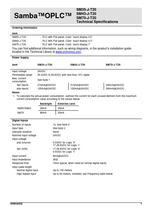
Samba™OPLC™ SM35-J-T20SM43-J-T20SM70-J-T20Technical SpecificationsOrdering InformationItemSM35-J-T20 PLC with Flat panel, Color touch display 3.5’’SM43-J-T20 PLC with Flat panel, Color touch display 4.3’’SM70-J-T20 PLC with Flat panel, Color touch display 7’’You can find additional information, such as wiring diagrams, in the product’s installation guide located in the Technical Library at .Power SupplyItem SM35-J-T20 SM43-J-T20 SM70-J-T20Input voltage 24VDCPermissible range 20.4VDC to 28.8VDC with less than 10% rippleMax. currentconsumptionSee Note 1npn inputs 215mA@24VDC 215mA@24VDC 340mA@24VDCpnp inputs 120mA@24VDC 120mA@24VDC 240mA@24VDCNotes:1. To calculate the actual power consumption, subtract the current for each unused element from the maximumcurrent consumption value according to the values below:Backlight Ethernet cardSM35/SM43 20mA 35mASM70 80mA 35mADigital InputsNumber of inputs 12. See Note 2Input type See Note 2Galvanic isolation NoneNominal input voltage 24VDCInput voltagepnp (source) 0-5VDC for Logic ‘0’17-28.8VDC for Logic ‘1’npn (sink) 17-28.8VDC for Logic ‘0’0-5VDC for Logic ‘1’Input current 8mA@24VDCInput impedance 3KΩResponse time 10ms typical, when used as normal digital inputsInput cable lengthNormal digital input Up to 100 metersHigh Speed Input Up to 50 meters, shielded, see Frequency table below2/15 Samba™ OPLC™High speed inputs Specifications below apply when wired as HSC/shaft-encoder.See Note 2Frequency (max) See Note 3Cable length (max.) HSC Shaft-encoder10m 30kHz 20kHz25m 30kHz 13kHz50m 25kHz 9kHzDuty cycle 40-60%Resolution 32-bitNotes:2. This model comprises a total of 12 inputs. Input functionality can be adapted as follows:12 inputs may be used as digital inputs. They may be wired, in a group, and set to eithernpn or pnp via a single jumper.In addition, according to jumper settings and appropriate wiring:Inputs 10 and 11 can function as either digital or analog inputs.Inputs 0, 2, and 4 can function as high-speed counters, as part of a shaft-encoder,or as normal digital inputs.Inputs 1, 3, and 5 can function as either counter reset, as part of a shaft-encoder,or as normal digital inputs.If inputs 0, 2, 4 are set as high-speed counters (without reset), inputs 1, 3, 5can function as normal digital inputs.3. pnp/npn maximum frequency is at 24VDC.Analog InputsNumber of inputs 2, according to wiring as described above in Note 2Input type Multi-range inputs: 0-10V, 0-20mA, 4-20mAInput range 0-20mA, 4-20mA 0-10VDCInput impedance 243Ω>150KΩMaximum input rating 25mA, 6V 15VGalvanic isolation NoneConversion method Successive approximationResolution (except 4-20mA) 10-bit (1024 units)Resolution (at 4-20mA) 204 to 1023 (820 units)Conversion time One configured input is updated per scan. See Note 4Precision 0.9%Status indication Yes – if an analog input deviates above the permissible range,its value will be 1024.Note:4. For example, if 2 inputs are configured as analog, it takes 2 scans to update all analog values.SMxx-J-T20 Technical Specifications 2/15Digital OutputsNumber of outputs 8 transistor pnp (source)Output type P-MOSFET (open drain)Isolation NoneOutput current (resistive load) 0.5A maximum per output3A maximum total per commonMaximum frequency 50Hz (resistive load)0.5Hz (inductive load)PWM maximum frequency 0.5KHz (resistive load). See Note 5Short circuit protection YesShort circuit indication Via softwareOn voltage drop 0.5VDC maximumPower supply for outputsOperating voltage 20.4 to 28.8VDCNominal voltage 24VDCNote:5. Outputs 0 to 6 can be used as PWM outputs.Graphic Display ScreenItem SM35-J-T20 SM43-J-T20 SM70-J-T20 LCD Type TFT, LCD display TFT, LCD display TFT, LCD display Illumination backlight White LED White LED White LED Display resolution 320x240 pixels 480x272 pixels 800x480 pixels Viewing area 3.5" 4.3" 7"Colors 65,536 (16-bit) 65,536 (16-bit) 65,536 (16-bit) Touchscreen Resistive, analog Resistive, analog Resistive, analog Screen brightness control Via software (Store value to SI 9, values range: 0 to 100%)Virtual Keypad Displays virtual keyboard when the application requires data entry.ProgramItem SM35-J-T20 SM43-J-T20 SM70-J-T20 Memory sizeApplication Logic 112KB 112KB 112KBImages 1MB 2MB 5MBFonts 512KB 512KB 512KBOperand type Quantity Symbol ValueMemory Bits 512 MB Bit (coil)Memory Integers 256 MI 16-bit signed/unsignedLong Integers 32 ML 32-bit signed/unsignedDouble Word 32 DW 32-bit unsignedMemory Floats 24 MF 32-bit signed/unsignedFast Bits 64 XB Fast Bits (coil) – not retainedFast Integers 32 XI 16 bit signed/unsigned (fast, not retained)Fast Long Integers 16 XL 32 bit signed/unsigned (fast, not retained)Fast Double Word 16 XDW 32 bit unsigned (fast, not retained)Timers 32T Res. 10 ms; max 99h, 59 min, 59.99sCounters 16 C 32-bitData Tables 32K dynamic data (recipe parameters, datalogs, etc.)16K fixed data (read-only data, ingredient names, etc)HMI displays Up to 24Program scan time 15µs per 1kb of typical application2/15 Samba™ OPLC™Communication PortsPort 1 1 channel, RS232 (SM35) , USB device (SM43/SM70)Galvanic isolation SM35 and SM43 – NoSM70 - YesBaud rate 300 to 115200 bpsRS232 (SM35 only)Input voltage ±20VDC absolute maximumCable length 15m maximum (50’)USB device (SM43,SM70 only)Port type Mini-BSpecification USB 2.0 complaint; full speedCable USB 2.0 complaint; up to 3mPort 2 (optional) See Note 6CANbus (optional) See Note 6Notes:6. The user may order and install one or both of the following modules:- A serial RS232/RS485 isolated/non-isolated interface module, or an Ethernet Interface module in port 2.- A CANbus modulemodules documentation is available on the Unitronics website.MiscellaneousClock (RTC) Real-time clock functions (date and time)Battery back-up 7 years typical at 25°C, battery back-up for RTC and system data, includingvariable dataBattery replacement Yes. Coin-type 3V, lithium battery, CR2450DimensionsItem SM35-J-T20 SM43-J-T20 SM70-J-T20Size 109 x 114.1 x 68mm(4.29 x 4.49 x 2.67”).See Note 7 136 x 105.1 x 61.3mm(5.35 x 4.13 x 2.41”).See Note 7210 x 146.4 x 42.3mm(8.26 x 5.76 x 1.66”).See Note 7Weight 205g (7.23 oz) 344g (12.13 oz) 633g (22.32 oz) Notes:7. For exact dimensions, refer to the product’s Installation Guide.EnvironmentOperational temperature 0 to 50ºC (32 to 122ºF)Storage temperature -20 to 60ºC (-4 to 140ºF)Relative Humidity (RH) 10% to 95% (non-condensing)Mounting method Panel mounted (IP65/66/NEMA4X)DIN-rail mounted (IP20/NEMA1)Operating Altitude 2000m (6562 ft)Shock IEC 60068-2-27, 15G, 11ms durationVibration IEC 60068-2-6, 5Hz to 8.4Hz, 3.5mm constant amplitude,8.4Hz to 150Hz, 1G acceleration.SMxx-J-T20 Technical Specifications 2/15 The information in this document reflects products at the date of printing. Unitronics reserves the right, subject to all applicable laws, at any time, at its solediscretion, and without notice, to discontinue or change the features, designs, materials and other specifications of its products, and to either permanently ortemporarily withdraw any of the forgoing from the market.All information in this document is provided "as is" without warranty of any kind, either expressed or implied, including but not limited to any implied warranties of merchantability, fitness for a particular purpose, or non-infringement. Unitronics assumes no responsibility for errors or omissions in the information presented inthis document. In no event shall Unitronics be liable for any special, incidental, indirect or consequential damages of any kind, or any damages whatsoever arising out of or in connection with the use or performance of this information.The tradenames, trademarks, logos and service marks presented in this document, including their design, are the property of Unitronics (1989) (R"G) Ltd. or other third parties and you are not permitted to use them without the prior written consent of Unitronics or such third party as may own them.DOC17017-A8 02/15。
PG0703P_C02A 等产品的编程手册说明书
目录1. 远程控制概述 (1)1.1 如何远程控制 (1)1.2 通信协议 (3)1.3 远程控制功能 (5)2. SCPI简介 (10)2.1 命令格式 (10)2.2 符号说明 (10)2.3 参数类型 (11)2.4 命令缩写 (12)3. 模式共用命令 (13)3.1 IEEE公用命令子系统 (13)3.2 系统命令 (15)3.3 存储命令 (20)3.4 显示控制 (21)3.5 模式命令 (22)3.6 扫描命令 (22)4. 频谱分析模式 (24)4.1 仪器模式命令 (24)4.2 Initiate命令子系统 (24)4.3 Sense命令子系统 (25)4.4 Calculate命令系统 (43)4.5 Measurement命令系统 (58)4.6 触发 (72)4.7 TG (73)4.8 调制解调 (75)5. 矢量网络分析模式 (77)5.1 频率控制 (77)5.2 幅度控制 (78)5.3 带宽控制 (80)5.4 扫描控制 (80)5.5 TG (81)5.6 迹线 (81)5.7 光标 (85)6. 故障定点分析模式 (98)6.1 频率控制 (98)6.2 幅度控制 (99)6.3 扫描控制 (100)6.4 迹线 (101)6.5 光标 (102)6.6 测量 (105)7. 调制分析模式 (110)7.1 频率控制 (110)7.2 幅度控制 (111)7.3 带宽控制 (112)7.4 扫描控制 (113)7.5 迹线 (114)7.6 光标 (117)7.7 测量 (119)7.8 触发 (124)8. 实时频谱分析模式 (126)8.1 频率控制 (126)8.2 幅度控制 (129)8.3 带宽控制 (131)8.4 扫描控制 (132)8.5 迹线 (134)8.6 光标 (137)8.7 触发 (139)8.8 测量 (142)9. EMI测量 (145)9.1 频率控制 (145)9.2 幅度控制 (147)9.3 带宽控制 (150)9.4 扫描控制 (151)9.5 迹线 (153)9.6 光标 (155)9.7 限制 (159)10. 编程示例 (168)10.1 使用VISA的编程示例 (168)10.2Sockets/Telnet示例 (182)SIGLENT 1. 远程控制概述分析仪支持通过USB、LAN、GPIB-USB接口与计算机进行通信。
PowerPad III Model 8333 用户手册说明书

PRODUCT PACKAGINGShipping Contents:(1) PowerPad ® III Model 8333Cat. #2136.10 / Cat. #2136.11 / Cat. #2136.12Also Includes:•4 GB USB Stick (DataView/User Manual)• 9.6V NiMh Battery - installed• 2 GB SD-Card - installed•High Voltage Warning/Caution CardKit (Cat. #2136.11) also includes:• (3) AmpFlex ®Model A193-24-BK Kit (Cat. #2136.12) also includes:• (3) AC Current Probe Model MN193-BK (1) Extra Large Classic Tool BagCat. #2133.73(1) Soft Carrying Pouch Cat. #2140.15(12) Color-coded ID MarkersCat. #2140.45(1) 5 ft USB CableCat. #2140.46(4) Black Test Leads and Alligator ClipsCat. #2140.44(1) Power Adapter 110/240V w/ Power CordCat. #5000.19USB STICK: DataView ® software and complete user manual for the Model 8333 can be located on the USB stick supplied with the instrument.Thank you for purchasing an AEMC® PowerPad® III Model 8333.For best results from your instrument and for your safety, read the enclosed operating instructions carefully and comply with the precautions for use. These products must be only used by qualified and trained users.Definition of Measurement Categories (CAT)CAT IV Measurement category IV corresponds to measurements taken at the source of low-voltage installations.Example: power feeders, counters and protection devices.CAT III Measurement category III corresponds to measurements on building installations.Example: distribution panel, circuit-breakers, machines or fixed industrialdevices.CAT II Measurement category II corresponds to measurements taken on circuits directly connected to low-voltage installations.Example: power supply to domestic electrical appliances and portable tools.This instrument is compliant with safety standard IEC 61010-2-030, the leads are compli-ant with IEC 61010-031, and the current sensors are compliant with IEC 61010-2-032, for voltages up to 600V in category IV or 1000V in category III. Failure to observe the safety instructions may result in electric shock, fire, explosion, and destruction of the instrument and/or other equipment.• The operator and/or the responsible authority must carefully read and clearly under-stand the various precautions for use of the instrument. Sound knowledge and a keen awareness of electrical hazards are essential when using this instrument.• If you use this instrument other than as specified, the protection it provides may be compromised, thereby endangering you.• Do not use the instrument on networks on which the voltage or category exceeds those mentioned.• Do not use the instrument if it appears damaged or otherwise compromised.• Before each use, check the condition of the insulation on the leads, housing, and accessories. Any item on which the insulation is deteriorated (even partially) must be set aside for repair or scrapping.• Before using your instrument, check that it is perfectly dry. If it is wet, it must be thor-oughly dried before being connected or being operated in any way. This includes the terminals and keypad.• Use only the leads and accessories supplied. Using leads (or accessories) of a lower voltage or category reduces the voltage or category of the combined instrument and leads (or accessories) to that of the leads (or accessories).• Always use personal protection equipment.• Keep your hands away from the terminals of the instrument.• When handling the leads, test probes, and alligator clips, keep your fingers behind the physical guard.• Use only the AC power cord and battery pack supplied by the manufacturer. They include specific safety features.• Some current sensors must not be placed on or removed from bare conductors at hazardous voltages: refer to the manual and comply with the handling instructions.Charging the BatteryFully charge the battery before the first use.120V ± 10%, 60Hz230V ± 10%, 50HzTo recharge the battery:• Remove the cover of the batterycharging connector.• Connect the supplied powercord to the instrument and ACpower.• disconnected.Button FunctionsControl Features1.Over molded protective housing2.LCD Display3.Six function buttons (yellow)4.Four function buttons (see chart, left)5.ON/OFF button6. Three current inputs and four voltage inputsB port8.Input for external power supplyand battery charging9.Confirm/Enter button10.Navigation buttons11.Six mode buttons (see chart, left)Connection Terminals1. Three (3) current inputs on the top of the instrument to enable the use of current sensors (MN,SR, AmpFlex®, MiniFlex®, MR, SL and J93 probes).2. Four (4) voltage inputs.3. Insertion locations for the current and voltage color-coded ID markers.Instrument ConfigurationNOTE: Instrument configuration can also be modified through DataView® software.NOTE: The instrument must be configured the first time it is used. The configuration is saved in memory when the instrument is turned OFF.Press the button to configure the unit. The following sub-menus appear:• Set the display language by pressing the yellow button corresponding to the screenlanguage icons.• The parameter that is ready to be configured will be highlighted in yellow. To move to a different parameter, use the ▲ and ▼ buttons.•button to select a parameter.• Use the ◄ and ► buttons to change a value or setting.• button.Getting StartedConnecting:• button.• Configure the instrument to obtain the required results and type of network.• Connect the current leads and sensors to the PowerPad®.• Connect the ground and/or neutral lead to the network ground and/or neutral (whendistributed), as well as the corresponding current sensor.• Connect the L1 phase lead to the network L1 phase, as well as the correspondingcurrent sensor.• Repeat the procedure for phases L2, L3 and N.Disconnecting:• Proceed in the reverse order to connecting, always finishing by disconnecting the• button to turn the instrument off.• Recharge the battery, if necessary.Installation of the Leads and Current SensorsColor-coded ID markers are supplied with the PowerPad® to identify the leads and input terminals.• Detach the appropriate inserts from the color-coded marker and place them in the holes provided under the terminals (larger inserts for current terminals, smaller inserts for voltage terminals).• Clip the rings of the same color to the ends of the lead that will connect to the terminal.SD-CardSD-Cards (up to 2GB only) are supported.To Access the SD-Card:• Make sure that the instrument is disconnected and off.• Use a screwdriver or coin to unscrew the two screws of the battery compartment cover.• Remove the cover and withdraw the battery from its compartment without disconnecting it.• Press on the SD-Card to release it then press on the protecting tab to withdraw it fromits slot.• When replacing the SD-Card, the contacts must be on the left side, and the locator down.• Slide it into its slot until it snaps into place. The protecting tab is at the top of the card.• Put the battery back in its compartment and screw the cover back on.Replacing the BatteryTO ELIMINATE ALL RISK OF ELECTRIC SHOCK, DISCONNECT THE POWER SUPPLY CORD AND MEASUREMENT LEADS FROM THE INSTRUMENT.1. Turn the instrument over, raise the stand, and prop it up.2. Use a coin to unscrew the two quarter-turn screws on the back of the housing.3. Using a flat screwdriver, remove the cover from the compartment.4. Turn the instrument over and hold the battery as it slides out of its compartment.5. Disconnect the battery connector without pulling on the wires.6. Connect the new battery. The connector is error-proofed to prevent reversals of polarity.7. Place the battery in its compartment and arrange the wires so that they do not protrude.8. Put the battery compartment cover back in place and screw the two screws back in. NOTE: If the battery is disconnected, it must then be fully recharged, even if it is not replaced, so that the instrument will know the battery charge condition (this information is lost when the battery is disconnected).Installing DataView®DO NOT CONNECT THE INSTRUMENT TO THE PC BEFORE INSTAL L ING THE SOFT-WARE AND DRIVERS.1. Insert the USB stick into an available USB port (wait for driver to be installed).2. If Autorun is enabled, an AutoPlay window should appear. If Autorun is disabled, it will benecessary to open Windows Explorer, then locate and open the USB stick drive labeled“DataView” to view the files on the drive.3. In the AutoPlay window, select “Open folder to view files.”4. Double-click on Setup.exe from the opened folder view to launch the Dataview® setupprogram.NOTE: For more information on using DataView®, refer to the product user manual that is supplied on the USB stick.Updating Software & FirmwareTo provide our customers the best possible service in terms of performance and technical upgrades, AEMC® offers free software and firmware updates on our website.• Visit us at: • Click on the TECH INFO tab, then click on the Software & Firmware Updates button. DataView® can also be updated by selecting “Update” from the Help menu within the software.Repair and CalibrationTo ensure that your instrument meets factory specifications, we recommend that it be scheduled back to our factory Service Center at one-year intervals for recalibration, or as required by other standards or internal procedures.For instrument repair and calibration:You must contact our Service Center for a Customer Service Authorization Number (CSA#). This will ensure that when your instrument arrives, it will be tracked and processed promptly. Please write the CSA# on the outside of the shipping container. If the instrument is returned for calibration, we need to know if you want a standard calibration, or a calibration traceable to N.I.S.T. (Includes calibration certificate plus recorded calibration data).Ship To:Chauvin Arnoux®, Inc. d.b.a. AEMC® Instruments15 Faraday Drive • Dover, NH 03820 USAPhone: (800) 945-2362 or (603) 749-6434 (Ext. 360)Fax: (603) 742-2346 or (603) 749-6309E-mail: ***************NOTE: You must obtain a CSA# before returning any instrument.Technical and Sales AssistanceIf you are experiencing any technical problems, or require any assistance with the proper operation or application of your instrument, please call, fax or e-mail our technical support team:Chauvin Arnoux®, Inc. d.b.a. AEMC® InstrumentsPhone: (800) 343-1391 or (508) 698-2115 (Ext. 351)Fax: (508) 698-2118E-mail: ********************Limited WarrantyThe Model 8333 is warranted to the owner for a period of one year from the date of original purchase against defects in manufacture. This limited warranty is given by AEMC® Instruments, not by the distributor from whom it was purchased. This warranty is void if the unit has been tampered with, abused or if the defect is related to service not performed by AEMC® Instruments.Full warranty coverage and registration is available on our website:/warranty.html.Please print the online Warranty Coverage Information for your records.What AEMC® Instruments will do: If a malfunction occurs within the warranty period, you may return the instrument to us for repair, provided we have your warranty registration on file or a proof of purchase. AEMC® Instruments will, at its option, repair or replace the faulty material.Warranty RepairsWhat you must do to return an Instrument for Warranty Repair:First, request a Customer Service Authorization Number (CSA#) by phone or e-mail from our Service Department, then return the instrument along with the signed CSA Form. Please write the CSA# on the outside of the shipping container. Return the instrument, shipment pre-paid to:Ship To:Chauvin Arnoux®, Inc. d.b.a. AEMC® Instruments15 Faraday Drive • Dover, NH 03820 USAPhone: (800) 945-2362 or (603) 749-6434 (Ext. 360)E-mail:***************Caution: To protect yourself against in-transit loss, we recommend you insure your returned material. NOTE: You must obtain a CSA# before returning any instrument.06/1699-MAN 100404 v3Chauvin Arnoux®, Inc. d.b.a. AEMC® Instruments15 Faraday Drive • Dover, NH 03820 USA • Phone: (603) 749-6434 • Fax: (603) 742-2346。
欧司朗OT Programmer-X OPTOTRONIC P7系列软件配置用户手册说明书
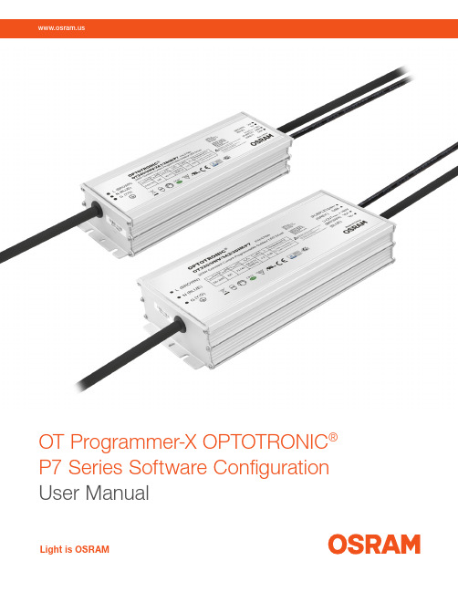
OT Programmer-X OPTOTRONIC®P7 Series Software Configuration User ManualLight is OSRAMOT Programmer-X OPTOTRONIC® P7 Series Software Configuration | User ManualTable of contents1. System requirements 22. Installing software 23. Installing USB drivers 44. Connection to LED driver 54.1 Button functions 65. Programming instructions 6 5.1 Set Iout 6 5.2 Signal dimming mode 6 5.3 AstroDIM mode 7 5.3.1 Traditional timing 7 5.3.2 Time based 8 5.3.3 Astro based 9 5.4 Constant lumen 10 5.5 OTP point 10 5.6 Read function 111 System requirements1.1 Hardware environment— CPU: 2GHz and above (32-bit or more)— RAM: 2GB and above— HD: 20GB and above1.2 Software environment—O perating system: Windows XP, Win7, Win10 or above—C omponent: Framework 4.0 or above2 Installing software2.1 Software packagesFigure 1: List of files2Installation | User Manual2.2 InstallationDouble click setup.exe to install software1. WelcomeFigure 2: Welcome pageClick "Next" button2. Select installation folderFigure 3: Select installation folderAfter installation folder is selected, click "Next" button34Installation | User ManualFigure 4: Confirm installation3. Confirm and complete installationFigure 5: Complete InstallationAfter installation is completed, the shortcut icon will appear onthe desktop.3 Installing USB driversFigure 6: USB Driver filesPlease install CDM20824_Setup (XP).exe if operating system is Windows XP or install CDM21228_Setup.exe if it is Win7 and above.5Connection to LED driver | User Manual4 Connection to LED driverFigure 7: Connection diagramFirst insert the OT Programmer-X into the USB port of the computer, and connect the other end to the LED driver DIM+/- (PURPLE and GRAY).Open the software and click “Connect” to connect the software to the LED driver.Figure 8: Connect to LED driver UIIf the connection is successful, the prompt “Succeed” will be displayed at the top of the interface. Product Model and corresponding default setting will be automatically read by software. At the same time, the U-I curve of the corresponding model is displayed on the left. The curve shows the working area (gray dotted box), programmed working area (orange area), constant power curve (red dotted line), output voltage range (Vmin ~ Vmax), full power voltage range and other information. The programmed working area changes according to the set current.6Programming instructions | User Manual4.1 Button functions5 Programming instructions5.1 Output currentFigure 9: Button functionsRead: Reading driver configuration parameters and display to the UI Default: Restoring the UI parameters to the factory default values Import: Importing the saved parameter values from a file and display them on the UISave: Saving the interface display parameter values to a file Programming: Writing the configured parameters to the driver Download to offline programmer: Write the configured driver parameters to the offline programmerNote: The offline programmer is a programming tool kit that can complete driver programming without relying on a computer. The kit is easy to use and quick to program. For detailed information about this product, please consult your account manager.I Max is fixed and depends on the driver design.I Set can be defined based on customer’s needs. To change the Iout, just input the value and click “Programming”.The blue operation range changes after the Iset is successfully done. The Vout max is shown at the right corner in red.Figure 10: Output current setting5.2 Signal dimming modeSignal dimmingis Analog 1-10V or 0-10.Figure 11: Signal Dimming7Programming instructions | User Manual5.3 AstroDIM modeAstroDIMis a timer based dimming mode that allows the user to configure a custom dimming schedule.5.3.1 Traditional timingIn Traditional Timing mode, after the power supply is powered on, it works according to the set “work step” time and output power. In this mode, the number of steps, steps time, and output powerare always the same. When in use, configure the steps in the orange box as shown below.Figure 12: Traditional timingProgramming instructions | User Manual5.3.2 Time basedClick “Time Based” and select the reference period.Figure 13: Time basedThe Time Based function is used to adapt to changes in night time length due to seasonal changes. To use this function, you need to set the parameters in "Reference period" first. The software will calculate the length of the current day’s night time according to the length of the previous day’s night time. Assuming "reference days" is set to 7 days, the average of the night time for the first 7 days is taken and applied as the night time for tonight. Then it will automatically adjust according to the proportion of steps.ExampleAssume that the parameters of each step are:—Step 1 is 2 hours and 30 minutes and the power is 100%;—Step 2 is 3 hours and 30 minutes and the power is 80%;—Step 3 is 2 hours and 0 minutes and the power is 50%.The total length of the three steps is 8 hours. According to the average of the night time in the previous 7 days, the night time is 10 hours. Then the duration of Step 1 will be automatically adjusted to:(2 hours and 30 minutes) × 10 ÷ 8 = 150 minutes × 10 ÷ 8 = 3 hours and 7.5 minutesSimilar to this calculation, the duration of Step 2 will be automatically adjusted to 4 hours 22.5 minutes, the duration of Step 3 is automatically adjusted to 2 hours and 30 minutes.89Programming instructions | User Manual5.3.3 Astro basedClick "Astro Based" and set the reference period, midnight point, and initial duration.Figure 14: Astro basedAstro Based dimming profile is referenced to the average middle of the night, calculated based on the average operation time over the defined Reference period.Reference period is a self-adapting percentage of the night time of the previous days.Midnight time is the actual calculated center point in the operating period. It is aligned with the time point depicted by the vertical red line.Initial duration is the preset lighting duration, and is shown as the red horizontal line on the time axis.Actual duration is the actual calculated lighting operation time, which is shown as the orange horizontal line on the time axis After the LED driver is turned on, it works according to the adaptive (actual time) step and time and output power. Unlike the other two timing modes, the midpoint alignment steps use relative time settings. The start time of Step 1 is 15:00, and the other steps are arranged in order.10Programming instructions | User Manual5.4 Constant lumenThe Constant Lumen feature accounts for LED depreciation over time. Select “Enable”, configurethe operation time and the corresponding output level, and click “Programming”.Figure 15: Constant lumenOutput level is the set current percentage, maximum 100%.The time unit is 1K hours and the maximum is 100kh, which must be arranged in ascending order.5.5 OTP pointIf the Over-Temperature Protection (OTP Point ) is triggered, the output power will be decreased to lower the temperature and protect the driver. 85°C is the default OTP setting, the user is able to setthe temperature value lower to limit the maximum Tc.Figure 16: OTP settingProgramming instructions | User Manual5.6 Read functionWhen the Read function is performed, the driver log will be displayed.Current Tc: Current driver Tc temperature.Historical Tc_Max: The highest Tc temperature recorded during the driver’s operating lifetime.Previous time Tc_Max: Record of the highest Tc since last Read function was performed.This Time Tc_Max: Record of the highest Tc during this use.Total working time: Record the total working time (operating hours).OTP times: Record of the OTP triggered times.Firmware Version: Driver firmware version.Figure 17: Read function11OSRAM is a registered trademark of OSRAM GmbH. Specifications subject to change without notice.© 2021 OSRAM SYLVANIA Inc.ECS-OT442 2-21OSRAM SYLVANIA Inc.200 Ballardvale StreetWilmington, MA 01887 USA 1-877-636-5267 /ds。
sq24903fbp规格书

sq24903fbp规格书全文共四篇示例,供您参考第一篇示例:一、产品介绍sq24903fbp是一款新型的电子产品,具有卓越的性能和多样的功能,适用于多种场合。
它采用先进的技术和材料制造,具有高质量的智能化特点,是现代科技发展的产物之一。
sq24903fbp不仅外观精美,而且功能齐全,深受用户的青睐。
二、外观设计sq24903fbp采用了时尚简约的外观设计风格,外壳选用高品质材料制成,具有抗压、防滑、耐磨损等特点。
产品尺寸适中,手感舒适,携带方便,适合各种场景的使用。
产品表面经过专业处理,手感光滑,不易留下指纹,给用户带来更好的体验。
三、性能参数1. 处理器:采用先进的处理器芯片,运行速度快,响应灵敏,具有低功耗和高性能的特点。
2. 存储容量:内置大容量存储空间,能够满足用户对数据存储的需求。
3. 电池续航:采用高性能电池,续航能力强,能够满足用户长时间使用的需求。
4. 屏幕显示:配备高清晰度显示屏,色彩饱满,视觉效果出色,适合观看影视、阅读等活动。
5. 操作系统:具有稳定、安全的操作系统,能够满足用户对各种应用程序的需求,同时确保系统的稳定性和安全性。
四、功能特点1. 多样化功能:sq24903fbp具有丰富的功能,包括但不限于通讯、娱乐、学习、办公等,满足用户多方面的需求。
2. 智能化操作:产品配备智能化操作系统和人性化的界面设计,操作简便,用户友好。
3. 高速连接:支持多种联网方式,具有稳定的网络连接能力,满足用户对高速网络的需求。
4. 多种传感器:具备多种传感器模块,实现各种智能感知功能,适用于生活、工作中的多种场景。
5. 安全保护:产品内置多重安全保护机制,保障用户信息安全和隐私保护。
五、应用场景sq24903fbp适用于各种场合,包括家庭、办公、商务出行、旅游等,为用户提供便捷、高效的电子产品解决方案。
无论是娱乐、学习还是工作,都能找到适合的应用环境。
六、总结sq24903fbp是一款结合了时尚设计和先进技术的电子产品,具有优秀的性能和多样的功能,能够满足用户的多方面需求。
PiPO品铂M3 3G说明书

平板电脑—M3(3G)使用手册您 好!感谢您购买本公司平板电脑。
为了使您尽快轻松自如地操作您的产品,我们随机配备了内容详尽的用户手册,您可以获取有关产品介绍、使用方法等方面的知识。
使用您的产品之前,请仔细阅读我们随机提供的所有资料,以便您能更好地使用该产品。
请随时备份您的数据资料到您的电脑上。
本公司对于因软件、硬件的误操作、产品维修、电池更换或其它意外情况所引起的个人数据的丢失和损坏不负任何责任,也不对由此而造成的其它间接损失负责。
同时我们无法控制用户对本手册可能造成的误解,因此,本公司将不对在使用本手册过程中可能出现的意外损失负责,并不对因使用该产品而引起的第三方索赔负责。
本手册信息受到版权保护,其任何部分未经本公司事先书面许可,不准以任何方式影印和复制。
本公司保留对本手册、三包凭证及其相关资料的最终解释权。
本产品符合GB/T 18220-2000手持式个人信息处理设备通用规范。
注意事项✧不要在高度潮湿的环境下使用适配器,切勿用湿的手足去碰适配器。
✧切勿用金属物体接触机器,这样容易造成机器短路。
✧请不要试图分解或改造本机,这样可能导致电击或妨碍产品质保。
✧清洁机器时,请使用柔软的布清洁表面。
请注意不要让液体进入机器内部。
✧禁止儿童单独玩耍本机,请勿摔落或与硬物摩擦撞击,否则可能导致机器表面磨花、硬盘损伤、数据丢失或其它硬件损坏。
✧本机被作为移动硬盘使用时,请按正确文件管理操作方法存储导出文件,任何操作导致的文件丢失,本公司概不负责。
建议及时备份存放在本机中的个人资料。
✧禁止本品使用超负荷电源、用力弯曲或用重物挤压电源线,以免引起发热造成火灾。
✧因为本产品的性能和功能而发生的变更,可能会不做另行通知,请您谅解。
✧若因固件程序升级而导致本产品的实际设置和使用方法等与本手册不一致,请访问本公司官方网站或拨打服务热线查询最新产品信息。
谢谢您的合作!功能说明●润眼屏幕:10.1英寸10点电容触屏,分辨率达1280*800,16:10 IPS 全视角。
65寸75寸86寸98寸100寸会议平板,智能会议平板参数方案

智能会议平板技术参数(品牌:融创方圆)型号:RC65SHW/RC75SHW/RC86SHW/RC98SHW/RC100SHW1、整机产品概述1)铝合金外框,表面拉丝并阳极氧化处理,铁壳后盖,主动散热;2)4mm物理钢化防暴高透玻璃;加强视觉效果,提升触摸体验;3)高速10点触控书写体验,更好的圆滑度,更快的书写速度;4)支持无线投屏(手机/平板/笔记本/PC)会议功能。
5)使用国际通用标准的OPS插槽,一体化插拔式设计,方便升级与维护,外部无可见电脑模块的连接线,机身美观。
6)前置扩展端口:1路PC-USB、1路TV-USB 1路方便用户拓展使用。
7)前置三合一电视电脑开关按键;一体化设计,既能在临时不用此设备的时候,集中学生注意力;也能节省能源,节能环保;同时还能延长机器寿命。
方便用户使用。
8)喇叭出音前置,防止因内嵌环境导致声音效果变质。
9)有单机/双击/左右快捷键同一界面上进行多人多点触摸操作控制显示的信息内容并具有人性化的点击、互动、查询、放大缩小、旋转、翻页等互动展示功能。
10)触摸菜单,支持任何通道书写、批注、截图等功能。
2、技术参数参考:(融创方圆)触摸激活不需要任何激活安全可按要求选择不同等级的钢化玻璃噪音无噪音透光材料ABS透光条安装方式嵌入壁挂式,环境工作温度0℃〜40℃储藏温度-20℃~55℃储藏湿度10%〜90% RH Non-Condensing 工作湿度20%〜80% RH Non-Condensing外观外壳材料金属外壳颜色白色+黑色,壁挂孔位参考700*400mm)包装附件电源线(L5M)x1遥控器*1,说明书x1,保修卡x1,触控笔x2,无线传屏器x1,壁挂支架x1备注以上详细规格参数有多项为可选功能,仅供参考,最终解释权归我司所有,可选功能会相应的增加费用,请按需选择相关功能参数,最终确认参数以业务人员相互确认为准。
- 1、下载文档前请自行甄别文档内容的完整性,平台不提供额外的编辑、内容补充、找答案等附加服务。
- 2、"仅部分预览"的文档,不可在线预览部分如存在完整性等问题,可反馈申请退款(可完整预览的文档不适用该条件!)。
- 3、如文档侵犯您的权益,请联系客服反馈,我们会尽快为您处理(人工客服工作时间:9:00-18:30)。
备注
第 1 页 总共 3 页
P73 技术参数
商科技术部
14 15 16 17 18 19 20 21 22 23 24 25 26 27 28 29 30 31 32 33 34 35 36 37 38 39 40 41 42 43 44 45
二、基本功能
编号 名称 1 2 3 4 5 6 7 8 9 10 11 12 13 无线 WIFI 上网功能 支持 USB Dongle 无线 3G 上网功能 支持以太网上网功能 蓝牙功能 媒体音量调节的功能 多种通知铃声选择功能 操作音的开关选择功能 按键触感功能 TF 卡通知的开关选择 功能 屏幕旋转和自动改变显 示方向的功能 窗口动画的显示功能 屏幕亮度调整功能 屏幕待机时间选择的功 能 详细列表 内容 支持(IEEE 802.11b/g/n) 支持 支持 不支持 支持 支持 支持 不支持 支持 支持 支持 支持 支持
46 47 48
最长录音时间(h) 传输速度 是否支持软件升级
录音时间为 900 小时(8GB) 读速度:5.0~12MB/S 写速度:2.9~4.0MB/S 支持
第 2 页 总共 3 页
P73 技术参数
商科技术部
49 50 51 52 53 54
பைடு நூலகம்
屏幕锁 电视输出功能 TF 扩展卡 复位功能 3D 重力传感器功能 外放喇叭功能
P73 技术参数
商科技术部
到货日期
到货种类 台电平板电脑
产品名称 P73
一、基本资料
编号 名称 1 2 3 4 5 6 7 8 9 10 11 12 13 主控芯片名称 操作系统 主频 SDRAM 外形尺寸(mm) 重量(g) 容量 接口规格 电池类型及电压 录音接口方式 驱动方式 操作键数量 耳机 RK2918 内置先进的 Google Android2.3 智能操作系 统 1.0GHz 512M DDR3 209mm (L) × 124mm(W)× 14mm(H) 431.4g 4G/8GB MINI USB 2.0(High Speed) 内置 4000mAh 聚合物锂电池 MIC 录音 WIN98 系统以上免驱 3 个机械键和 3 个触摸键 台电耳机 详细列表 内容 备注
以上为初版信息,仅供参考,如有不符,请以实物为准
第 3 页 总共 3 页
屏幕解锁图案的设置功 能 具有管理、删除、应用 程序的功能 支持电子书阅读功能 音频播放功能 视频播放功能 图片浏览功能 GMAIL 邮件收发功能 浏览器功能 浏览器 Flash 插件 办公软件、日程记事的 功能 桌面设置功能 摄像头功能 摄像头规格 录音功能 游戏功能 TF 卡外接功能 TF 卡信息显示的功能 TF 卡格式化及卸载的 功能 触控手写输入的功能 OTG 外接功能 HDMI 电视输出功能 语言和键盘选择的功能 日期和时间设置的功能 触摸屏校正的功能 USB 模式选择的功能 更新媒体库的功能 设备信息显示的功能 屏幕加解锁功能 显示屏类型 显示屏点阵 信噪比(dB) 最长播放时间(h)
支持 不支持 最大支持 32GB 容量 支持 支持 支持 快速操作指南 保修卡 耳机 一本 一本 一副 一条 一个 注意:DC 口 充电器原装 内置彩盒内。
55
附件
MINI USB 数据线 DC 口充电器
输入:AC100~240V 50/60Hz Max:600mA 输出:DC5.0~5.5V—2.0A~2.5A(DC)
支持 支持 支持 支持 支持 支持 支持 支持 支持(内置 Adobe Flash Player 10.2) 支持 支持 支持(拍照和录像) 前置摄像头(30W 像素) 支持 支持 支持 支持 支持 支持 支持 不支持 支持 支持 (电容屏不需要) 不支持 支持(自动更新) 支持 支持 采用 7 英寸 16:9 高清电容式触摸液晶屏 1024*600 大于或等于 90dB音频 视频 上网 约 12 小时(使用耳机) 约 5 小时(使用耳机) 约 5 小时