三相储能变流器操作手册
三相交流电源TFC63系列操作手册V1.0说明书
Three Phase AC SourceTFC63 Series Operation Manual V1.0SAFEFY INSTRUCTION................................................................................................................................... - 2 -1. KEY POINTS TO INSTALLATION ............................................................................................................ - 3 -1.1 Unpacking and Examination ................................................................................................................ - 3 -1.2 Preparation before Use.......................................................................................................................... - 3 -1.3 Storage and Shipping ............................................................................................................................ - 4 -2. SPECIFICATOINS ......................................................................................................................................... - 5 -2.1 Serial Lineup and Features................................................................................................................... - 5 -2.2 Specifications.......................................................................................................................................... - 6 -2.3 Block Diagram ....................................................................................................................................... - 7 -3. OPERATION INSTRUCTIONS.................................................................................................................... - 8 -3.1 Front Panel Description ........................................................................................................................ - 8 -3.2 Operation Instructions .......................................................................................................................... - 9 -3.2.1 Power On ................................................................................................................................... - 9 -3.2.2 Setting Mode .............................................................................................................................. - 9 -3.2.3 Output Mode ............................................................................................................................ - 10 -3.2.4 Error Mode ............................................................................................................................... - 10 -3.3 Operation Instructions to Buttons...................................................................................................... - 11 -4. FAULTS AND TROUBLE SHOOTING..................................................................................................... - 12 -5. MAITENANCE ............................................................................................................................................. - 13 -5.1 Inspection ............................................................................................................................................. - 13 -5.2 Cleaning................................................................................................................................................ - 13 -5.3 Modification ......................................................................................................................................... - 13 -Use of Operation ManualPlease read through and understand this Operation Manual before operating the product. After reading, always keep the manual nearby so that you may refer to it as needed. When mobbing the product to another location, be sure to bring the manual as well.Calibration notificationWe notify that the instruments included in this manual are in compliance with the features and specifications as stated in this manual. Before shipment, the instrument has been calibrated in factory. The calibration procedures and standards are compliant to the national regulations and standards for electronic calibration.WarrantyWe guarantee that the instrument has been passed strict quality check. We warrant our instrument’s mainframe and accessories in materials within the warranty period of one year. We guarantee the free replacement or repair of products which are approved defective. To get repair service, please contact with your nearest sales and service office. We do not provide any other warranty items except the one being provided by this summary and the warranty statement. The warranty items include but not being subjected to the hinted guarantee items related to tradable characteristics and any particular purpose. We will not take any responsibility in cases regarding to indirect, particular and ensuing damage, such as modifications to the circuit and functions by the users, repairing or component replacement by the users, or damage during transportation.For product improvement, the specifications are subject to change without prior notice.SAFEFY INSTRUCTIONThis chapter contains important safety instructions that you must follow when operating the AC power supply and when keeping it in storage. Read the following before any operation to insure your safety and to keep the best condition for the instrument.Safety SymbolsThe following safety symbols may appear in this manual or on the instrument:WARNINGIdentifies conditions or practices that could result in injury or loss oflife.CAUTIONIdentifies conditions or practices that could result in damage to theinstrument or to other properties. DANGERHigh voltageATTENTION Refer to the manual Protective conductor terminalOperation instructionSafety GuidelinesCAUTION●Before plugging into local AC mains, check and make sure that the output voltage is compatible to the load. (It is suggested to disconnect a load before plugging into local AC mains. ● Do not use this instrument near water.● Do not operate or touch this instrument with wet hands.● Do not open the casing of the instrument when it is connected to ACmains.● Avoid touch the metal contact part of the output terminals.● Do not use the instrument in an atmosphere which contains sulfuric acidmist or other substances which cause corrosion to metal.● Do not use the instrument in a dusty place or a highly humid place assuch will cause instrument reliability degradation and instrument failures.● Install the instrument in a place where is free from vibration.● Install the instrument in a place where the ambient temperature is inrange of -20~60℃. Note that the instrument operation may become unstable if it is operated in an ambient temperature exceeding the range of 0~40℃Power supplyWARNING AC Input voltage: 220V (single phase) /380V (three phase) ±10%, 50/60Hz Connect the protective grounding conductor of the AC power cord to an earth ground to avoid electrical shock.FuseWARNING● Make sure the correct type of fuse is installed before power up.● Replace the AC fuse with the same type and rating as the original fuse. ● Disconnect the power cord before fuse replacement.● Make sure the cause of fuse blowout is fixed before fuse replacement.1. KEY POINTS TO INSTALLATIONThis chapter introduces the rules of product unpacking, examination, preparation of pre-use and storage.1.1 Unpacking and Examination1. Unpack the AC power supply and check the enclosed accessories. During unpacking, DO NOTmake the power supply cabinet slope for more than 45 degrees.2. The product is sealed in a packing case which is protected by EPE foarm. If there are any damages with the packing case, please check the AC power supply and see if there is any deformation, scratch or panel damaged.3. In case of any damage, please inform us or local distributor immediately. Our service center will maintain it or replace it with a new one. However, please do not return it without a notification to us or local distributor.Packing list:AC power supply: 1 unit Operation manual: 1 pcs RS232 cable: 1pcs (optional) RS485cable: 1pcs (optional)1.2 Preparation before UseInput PowerThe input power requirements of the instrument are 220V±10% (50Hz±10%) single phase AC or 380V±10% (50Hz±10%) three phase AC. Please use a proper input power before turn on the AC power supply, and use a fuse with same specification of the original. The fuse specification is indicated on the rear panel of the power supply.WARNINGDisconnect the power cord before fuse replacement.WARNINGAlways keep good connection of the grounding wire and make sure to connect the grounding wire to the earth. The 3-pin power plug of the power supply must be connected to a socket with grounding wire. To use a longer wire, make sure it is perfectly grounded to the earth. When the 3-pin power plug of the power supply is plugged into a socket with grounding wire, the power supply has been grounded to the earth.Operation EnvironmentLocation: The installation sites must be away from chemical deposition, explosive material, sulfuric acid mist or other substances which cause corrosion to metal. The installation site shall always keep lean and dry, and free from dusty, high humidity and vibration. Relative Humidity: < 80% Altitude: < 2000m Temperature: 0℃ to 40℃1.3 Storage and ShippingEnvironmentLocation: The storage sites and transportation environment must be away from chemical deposition, explosive material, sulfuric acid mist or other substances which cause corrosion to metal. The installation site shall always keep lean and dry, and free from dusty, high humidity and vibration. Relative Humidity: < 80%Altitude: <7620mTemperature: -20℃ to 55℃The power supply must avoid extreme temperature change, because drastic temperature change will cause vapor condensation inside the power supply.Packing●Original PackingPlease keep all the original packing materials and pack the power supply if it must be sent back to us for repairing. And contact our service center before returning. All the accessories included with the power supply must be returned along with the power supply, and demonstrate the damage or malfunction. In addition, please mark the package with a label indicating FRAGILE AND HANDLE WITH CARE.●Other PackingIf the original packing materials are not found, please follow the following instructions to pack the power supply:1.Pack the power supply with bubble plastic bag or EPE foarm.2.Put it into a multi-layer carton which can withstand a weight of 150kg.e shockproof materials to filled around the power supply with thickness of 70~100mm.4.Seal the carton properly.5.Marked the carton with a label indicating FRAGILE AND HANDLE WITH CARE.2. SPECIFICATOINS2.1 Serial Lineup and FeaturesMain FeaturesPerformance Adopts RF SPWM regulation technology, fast response speed, good stability High power MOS/IGBT drive, reliable operation, strong over load capacityOperation Full range adjustable output: 0~150V, 0~300V, step 0.1VOutput frequency: 50Hz, 60Hz, 47-63Hz, 100Hz, 200Hz, optional 400HzFast output key for 220V/50Hz, 110V/60Hz and 120V/60HzTiming function, for output control 0~16 hoursHigh accuracy LED display for voltage, current, frequency, active power,power factorFast transient response, response time no more than 2ms for 100% load and unloadProtection Over voltage, over current, over load, and over temperature protectionsInterface RS232 (optional)RS485 (optional)Applications Automotive test systemBest power source for R&DElectronic/electrical products testSwitching power supply and transformer testCompressor and motor testMonitor testAir-conditioning equipments testFluorescent rectifier testFactory use for QC, life test, etc.400Hz switching power supply for military, airport and navigation systems, supercomputer, etc.2.2 SpecificationsGeneral specificationsCircuit mode IGBT/PWMInput 1φ2W, 220V±10% or 3φ4W, 380V±10%, 50±5Hz OutputPhase 3 phase, Phase difference: 120°±2°Low range Phase voltage 0V-150V, Line voltage 0-260V High range Phase voltage 0V-300V, Line voltage0-520VFrequencyAdjustable output: 47-63Hz, optional 45-400Hz Fixed output: 50Hz, 60Hz, 100Hz, 200Hz, optional 400HzFrequency accuracy ≤0.01%Line regulation ≤1%Load regulation ≤1%Harmonic distortion ≤2% (tested with resistive load)Efficiency ≥80%Response time Max.2msMeter & ResolutionFrequency meter 4 digits LED, resolution 0.1HzVoltmeter 4 digits LED, resolution 0.1VAmmeter 4 digits LED, resolution 0.1A/0.01APower meter 4 digits LED, resolution 0.1kW /0.001kWPreset function Preset output voltage, output frequency and output voltage floating ratio Hot key function Hot key for frequency switch, output voltage floating selectionAlarm function Audible and visual alarm once protective device activated; display errorcode on LEDProtectionFuse switch for input and output;Fast-response circuit to detect over voltage, over current, over load, over temperature and short circuit; Output will be shut down in protectionmode.Cooling Forced ventilation Cabinet protection grade IP2XOperation environmentTemperature: 0℃-45℃Humidity : 0-90% (Non-condensing) Altitude : 1500 feetOutput specifications (3 phase input)Model 6303 6306 6310 6315 6320 6330 Total outputcapacity3KVA 6KVA 10KVA 15KVA 20KVA 30KVAOutput capacity perphase1KVA 2KVA 3.3KVA 5KVA 7KVA 10KVAMax. current 1.0V-150V 8.4A 16.8A 28A 42A 58A 84A 150.1V-300V 4.2A 8.4A 14A 21A 29A 42AOutput specifications (3 phase input)Model 6345 6360 63100 63150 63300 63450 Total outputcapacity45KVA 60KVA 100KVA 150KVA 300KVA 450KVAOutput capacity perphase15KVA 20KVA 33KVA 50KVA 100KVA 150KVAMax. current 1.0V-150V 126A 168A 276A 416A 834A 1260A 150.1V-300V 63A 84A 138A 208A 417A 630A2.3 Block Diagram3. OPERATION INSTRUCTIONS 3.1 Front Panel Description1 2 3 4 5 6 7 10 11 12 13 814 9 15 16 17 18 19Fig 3.1 Front panel1 Voltage meter for phase A: displays setting voltage and output voltage2 Voltage meter for phase B: displays setting voltage and output voltage3 Voltage meter for phase C: displays setting voltage and output voltage4 Current/Watt meter for phase A: displays output current/active power5 Current/Watt meter for phase B: displays output current/active power6 Current/Watt meter for phase C: displays output current/active power7 Current/Watt indicator: when the “A” indicator lights on, the meter displays output current and its unit is “A”. When the “kW” indicator lights on, the meter displays active power and its unit is “kW”. When both indicators light off, the meter display power factor. 8 Frequency meter: display setting frequency and output frequency.9 Start indicator: lights on to indicate that the power source is already started. 10 Upper float key 11 Lower float key 12 Switch key13 Hot key for output frequency switch between 50Hz and 60Hz 14 Parameter setup key15 Start key: press to start the power source 16 “+” key: press to increase parameter 17 “-” key: press to decrease parameter 18 Stop key: press to stop output19 Current/Watt key: press to switch display between current, active power and power factor3.2 Operation InstructionsWARNING ●Before connecting to local AC mains check and make sure to usecorrect AC power to the power supply.●Connect the protective grounding conductor of the AC power cord to anearth ground to avoid electrical shock.●Switch off all switches.●Ensure 200mm space for front and back sides of the AC power sourcefor purpose of good ventilation.●Do not use the AC power source when there is thundery weather.3.2.1 Power OnPress the power button to turn on the power supply. There will be 10 seconds of soft start delay before the AC power source enters standby status (refer to below for standby status)Standby modeNOTE: All buttons has no response to operation during soft start.3.2.2 Setting ModePress SET button to go into setting mode. Press + or - button to increase or decrease parameters of frequency, voltage, upper or lower float. After parameter setup is finished, press Stop button to return to standby mode.Setting mode3.2.3 Output ModeIn standby mode, press Start button to start output. The LED displays output voltage, load current and watt. Press Current/Watt button to switch meter display between current, active power and power factor.Output mode, display current of all 3 phasesOutput mode, display active power of all 3 phasesWARNING Even if the output and input of the AC power source are isolated, dangerousvoltage on the output terminals remain as a jeopardize to operator of thisunit. Press Stop button to stop output and get back to standby mode.3.2.4 Error ModeWhen there is error to the AC power source, there will be audible and visual alarm, and the unit will go into error mode. The LED will display error code. Press Stop button to stop alarm and get back to standby mode.Error mode3.3 Operation Instructions to ButtonsButton Operation instructionsStop a)To stop output in output mode.b)To stop alarm.c)To exit parameter setup in setting mode.Start In standby mode, press to start output.SET a)Press once to go into frequency setup.b)Make a 2nd press to go into voltage setup.c)Make a 3rd press to go into voltage upper float setup (setting range5%~20%).d)Make a 4th press to go into voltage lower float setup (setting range-5%~-20%).e)Make a 5th press to exit setting mode and store all settings.Press this key once again to recycle the above operations.+ a)In output mode, press this button to increase output voltage.b)In setting mode, press this button to increase setting parameter.- a)In output mode, press this button to decrease output voltage.b)In setting mode, press this button to increase setting parameter.Upper float In output mode, press this button to increase output voltage. Lower float In output mode, press this button to decrease output voltage.50Hz/60Hz/400Hz A key shortcut to switch between 50Hz, 60Hz and 400Hz output in output mode or in setting mode.Current/Watt In output mode, press to switch between display of current, active power and power factor.4. FAULTS AND TROUBLE SHOOTINGFault Power switch indicator dose not light on after connected to local AC mains.Causes 1.The input power plug is not properly connected.2.The fuse is blown.Clear 1.Check if the power plug is properly connected.2.Disconnect from local AC mains and replace fuse with same specificationFault Error code displayed on LED.Causes There is big impact loads connected to the grid, for example, welding machine, controlled rectifier device. It can be caused by thunder.Clear Turn off the AC power source and restart it.Fault There is alarm and LED displays 000X.Causes Find out the cause according to error code.0001: Short circuit protection.0002: Over temperature protection.0003: Over current protection.Clear Clear error according to error code, and restart the AC power source. If it is caused by over temperature protection, restart the unit after 5 minutes.If the faults cannot be cleared, please notify our service center or local distributor.5. MAITENANCE5.1 Inspection●Inspect the power supply at regular intervals so that it maintains its initial performance for along time.●Check the input power cord for damage of the vinyl cover and overheating of the plug and cordstopper. Check the terminal screws and binding posts for loosening.●Remove dust from the inside of the casing and ventilation holes of the cover by using acompressed air of the exhaust air of a vacuum cleaner.●If the power supply has not been used for a long time, please power on the power supply towarm up for two hours every three months.5.2 Cleaning●Before cleaning, disconnect the AC mains.●To clean the power supply, use a soft cloth dampened in a solution of mild detergent and water.Do not spray cleaner directly onto the power supply, since it may leak into the cabinet and cause damage.●Do not use chemicals containing benzene, benzene, toluene, xylene, acetone, or similarsolvents.●Do not use abrasive cleaners on any portion of the power supply.5.3 ModificationNo any modifications to the circuit or the components can be made to the power supply by the users. In case of any modifications by the users, the warranty will automatically expire with the power supply. And we do not take any responsibility hereafter incurred. If the returned unit be found with any modifications, we will make the power supply to the original status and charge for maintenance service.。
GDB-V3三相电压变送器使用说明书
1. 注意产品标签上的辅助电源信息,变送器的辅助电源等级和极性不可差错,否则将损坏变送器。 2. 变送器为一体化结构,不可拆卸,同时应避免碰撞和跌落。 3. 变送器在有强磁干扰的环境中使用时,请注意输入线的屏蔽,输出信号应尽可能短。集中安装时,最小安装间
隔不应小于 10mm。 4. 只能使用变送器的有效接线端,其它端子可能与变送器内部电路有连接,不能另图它用。 5. 当输入量超过额定值时,输出量会被限制在大约 1.2 倍额定输出值上。 6. 本系列变送器内部未设置防雷击电路,当变送器输入、输出馈线暴露于室外恶劣气候环境之中时,应注意采取
本系列部分产品采用 DIN 导轨卡装式结构,插拔式端子接线,安装、维护方便,适用于各种工控监测系统、单片 机数据采集、信号传输转换和 DCS 集散控制系统等,可广泛应用于电力、通信、铁路、矿山、冶金、交通、仪表等行 业。
二、GDB-V3 三相电压变送器选型及参数表
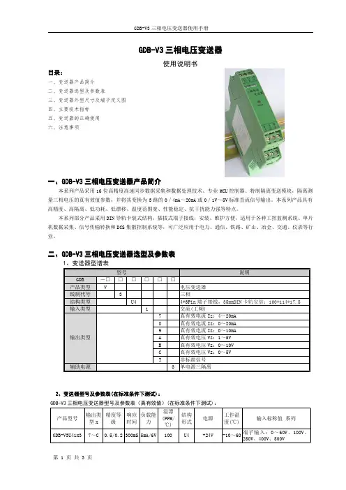
1、变送器型谱表
GDB 产品类型 线制代号 结构类型 输入类型
防雷措施。 7. 本产品采用阻燃 ABS 塑料外壳封装,外壳极限耐受温度为+85℃,收到高温烘烤时会发生变形,影响产品性能。
产品请勿在热源附近使用或保存,请勿把产品放进高温箱内烘烤。 8. 请勿损坏或者修改产品的标签、标志,请勿拆卸或改装变送器,否则本公司将不再对该产品提供“三包”(包换、
GDB-V3 三相电压变送器使用手册
目录:
一、变送器产品简介 二、变送器选型及参数表 三、变送器外型尺寸及端子定义图 四、主要技术指标 五、变送器的正确使用 六、注意事项
GDB-V3 三相电压变送器
使用说明书
一、GDB-V3 三相电压变送器产品简介
本系列产品采用 16 位高精度高速同步数据采集和数据处理技术、专业 MCU 控制器、特制隔离变送模块,隔离测 量三相电压的真有效值参数,并将其变换为 3 路的 0/4mA~20mA 或 0/1V~5V 标准直流信号输出。本系列产品具有 高精度、高隔离、低功耗、低漂移、温度范围宽、性能稳定、抗干扰能力强等特点。
三相380V通用变频器说明书
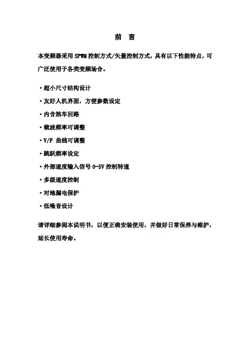
前言本变频器采用SPWM控制方式/矢量控制方式,具有以下性能特点,可广泛使用于各类变频场合。
·超小尺寸结构设计·友好人机界面,方便参数设定·内含煞车回路·载波频率可调整·V/F 曲线可调整·跳跃频率设定·外部速度输入信号0-5V控制转速·多级速度控制·对地漏电保护·低噪音设计请详细参阅本说明书,以便正确安装使用,并做好日常保养与维护,延长使用寿命。
1、注意事项1.1必须由具有专业资格的人员才能对控制器进行调试、维修或检查。
操作前请仔细阅该使用手册。
1.2 确认输入电源处于完全断开的情况下,才能进行配线作业。
1.3 不要把输入端子(Z,Y,X)与输出端子(U,V,W) 混淆,否则会损坏变频器。
1.4 将变频器的接线地端子可靠接地,否则有触电危险。
1.5 通电情况下,不要用手触摸控制端子,否则有触电危险。
1.6 在充电指示灯彻底熄灭或正负母线电压在36V以下时进行,否则有触电的危险。
1.7 防止螺钉,垫片及金属之类的异物掉进变频器内部,否则有火灾及损坏财务的危险。
1.8 主回路接线用电缆端头的裸露部分,一定要用绝缘胶带包扎好,否则有损坏财物的危险。
2.标准规格3.操作面板图SEL键:左移键MENU:菜单键;RUN/STOP:运行/停止/确定键4.安装及使用为了更好使用变频器,延长其工作寿命,安装使用场合请注意以下几点:1、周围环境温度:-10℃-45℃,且通风良好。
2、不宜在滴水或过分潮湿的场合使用。
3、不宜在振动强烈,电磁干扰严重的场合使用。
4、较少尘埃、无腐蚀性液体的场合。
5、不宜在靠近易燃性物体的场合使用。
6、2台变频器不能上下一条直线上安装,尽量保持空气流通,散热良好;7、使用期间切忌用手接触内部器件。
8、要及时进行定期检修。
5.端子说明与配线6.机能说明机能设定一览表7.机能设定方法7.1菜单项的使用:按键次序 显示内容8.开关机操作:8.1按“RUN/STOP”键,面板控制有效时,运行/停止变频器工作。
EM340 三相能量计说明书
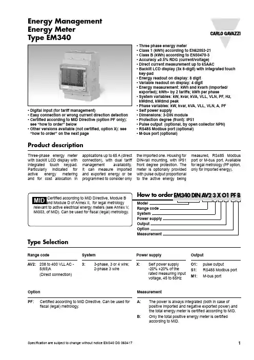
• Three phase energy meter• Class 1 (kWh) according to EN62053-21• Class B (kWh) according to EN50470-3• Accuracy ±0.5% RDG (current/voltage)• Direct current measurement up to 65AAC• Backlit LCD display (3x 8-digit) with integrated touch key-pad• Energy readout on display: 8 digit • Variable readout on display: 4 digit• Energy measurement: kWh and kvarh (imported/exported); kWh+ by 2 tariffs; kWh per phase• System variables: kW, kvar, kVA, VLL, VLN, PF, Hz, kWdmd, kWdmd peak• Phase variables: kW, kvar, kVA, VLL, VLN, A, PF • Self power supply• Dimensions: 3-DIN module • Protection degree (front): IP51• Pulse output (optional, by open collector NPN)• RS485 Modbus port (optional)• M-bus port (optional)Product descriptionThree-phase energy meter with backlit LCD display with integrated touch keypad. Particularly indicated for active energy metering and for cost allocation in applications up to 65 A (direct connection), with dual tariff management availability. It can measure imported and exported energy or be programmed to consider only the imported one. Housing for DIN-rail mounting, with IP51 front degree protection. The meter is optionally provided with pulse output proportional to the active energy beingmeasured, RS485 Modbus port or M-bus port. Available for legal metrology (PF option, only for imported energy).• Digital input (for tariff management)• Easy connection or wrong current direction detection • Certified according to MID Directive (option PF only): see “how to order” below• Other versions available (not certified, option X): see “how to order” on the next pageEnergy Management Energy Meter Type EM340relevant to active electrical energy meters (see Annex V, MI003, of MID). Can be used for fiscal (legal) metrology.Type SelectionRange codeAV2: 208 to 400 VLL AC -5(65)A(Direct connection)Power supply X:Self power supply -20% +20% of the rated measuring input voltage, 45 to 65HzOutput O1: pulse output S1: RS485 Modbus port M1:M-bus portSystem 3:3-phase, 3 or 4 wire; 2-phase 3 wireOption PF:Certified according to MID Directive. Can be used for fiscal (legal) metrology.Measurement A:The power is always integrated (both in case ofpositive imported and negative exported power) and the total energy meter is certified according to MID.B:Only the total positive energy meter is certified according to MID.EM340Not certified according to MID Directive. Cannot be used for fiscal (legal) metrology.Type SelectionRange codeAV2:208 to 400 VLL AC -5(65)A(Direct connection)Power supplyX:self power supply-20% +20% of therated measuring inputvoltage, 45 to 65HzOutputO1:pulse outputS1:RS485 Modbus portM1:M-bus port System3:3-phase, 3- or 4-wire;2-phase 3-wireOption X: noneEM340Input specificationsEM340Output specificationsDigital input specificationsInput specifications (cont.)or PF>0.996 (<5°) if capacitive- a current at least equal to10% rated current (primary current transformer)Digital inputs Free of voltage contact FunctionTariff management (switch between t1-t2)Number of inputs 1 Contact measurement voltage 5 V Input impedance 1kohm Contact resistance ≤1kohm, close contact≥100kohm, open contactOverloadIn case a voltage iserroneously applied to the digital input, the input is not damaged up to 30 VAC/DC.EM340General specificationsOutput specifications (cont.)Pulse ON duration Selectable: 30ms or 100 ms according to EN62052-31 Output typeOpen collector NPNLoad V ON 1 VDC max. 100mA V OFF 80 VDC max.EM340Accuracy (according to EN50470-3 and EN62053-23)Power supply specificationsSelf power supply208 to 400VAC VLL, -20% +20% 50/60HzPower consumption≤ 1W, ≤ 10VAInsulation (for 1 minute) between inputs and outputskWh,accuracy (RDG) depending on the currentClass 1 accuracy limits (Active energy)5(65)A Start-up current: 20mA Percentage error limits for class index B+1.5%+1%0%-1%-1.5%PF=10.25A(I min )0.5A(I tr )5A(I n )65A(I max )0.5A(I tr )5A(I n )65A(I max )PF=L0.5or C0.8(0,1I ref )(0,1I ref )(0.05I ref )kvarh,accuracy (RDG) depending on the currentClass 2 accuracy limits (Reactive energy)5(65)A Start-up current: 20mAError+2.5%+2%0%-2%-2.5%sin j =10.25A0.5A 5A(Ib)65A(I max )1A5A(Ib)65A(I max )sin j =0.5(0.1Ib)(0.25Ib)0.5A(0.05Ib)(0.1Ib)EM340Display pagesX= availableEM340Additional available information on the displayWiring diagramsEM340Wiring diagrams (cont.)EM340Front panel description1. DisplayBacklit LCD display with touch key-pad.2. LEDLED proportional to kWh reading3. Serial numberArea reserved to serial number and MID-relevant data inPF versionsDimensions。
三相储能变流器操作手册

不确认设备电压或温度的情况下切勿触碰设备的带电部件。
只有专业的电工或具备专业资格的人员才能安装、操作、检修和维护该设备。在维护或检修时,必须保证至少两名人员在现场,穿安全防护鞋,戴绝缘手套,同时树立警告标识。
对本产品的操作必须遵照本手册的安全说明进行,并严格遵守本产品安装手册中的所有安全说明。
本章概述
本章介绍了PSCCONVERTER-I10/3三相储能变流器用户使用手册的主要内容、面向的读者、以及手册使用须知,以便帮助用户更好地阅读、使用本手册。
本章内容
1.1 前言
1.2 内容介绍
1.3 面向读者
1.4 手册使用
1.1前言
尊敬的用户:
感谢您选用天津天海源电气技术有限公司的(以下简称本公司)PSCCONVERTER-I10/3三相储能变流器!在使用此产品前,请先仔细阅读本使用手册。
8.3.3应用接线图例37
8.3.4硬件与上位机操作步骤ﻩ38
8.3.5实测波形39
8.4典型应用4:并网定电流充电控制模式ﻩ40
8.4.1并网定电流充电控制模式简介ﻩ40
8.4.2应用目的ﻩ40
8.4.4硬件与上位机操作步骤41
8.4.5实测波形41
九附录ﻩ43
9.2联系我们ﻩ46
一关于本手册的说明
警告:违反以下规定,可能导致人员伤害或设备损坏。
移动、运输和放置设备时,必须保证设备水平放置。
应安装于阻燃性的物体上,箱体内和附近不要放置易燃物品。
2.2安全标志约定
本手册内安全风险将采用以下安全标志予以标识:
危险:可能存在导致人身伤害甚至死亡的危险。
警告:可能存在引起人身伤害或设备损坏的危险。
Eaton Power-Sure 700三相电压调节器说明说明书

Eaton Power-Sure 700 (10–500 kVA,three-phase voltage regulator)The Eaton Power-Sure ™ 700 reduces equipment downtime through constant voltage regulation. It is the ideal solution for equipment orfacilities experiencing brownouts and voltage regulation problems. The unique design of the Power-Sure 700 offers a high in-rush current, rapid response and operating advantages over other manufacturers.OverviewThe appropriate transformer tap is automatically activated through a silicon-controlled rectifier (SCR), maintaining a tightly regulated output voltage. Tap changes are initiated within one electrical cycle—switching at zero current crossing to ensure a minimum amount of noise during tap transitions. Seven taps per phase are used for optimal voltage regulation. Also, the Power-Sure 700 is a low output impedance, shielded isolation transformer. As a result of the lowimpedance, load changes do not affect other equipment connecting the system.The Power-Sure 700’s unique design ensures high efficiency at 97% and 1000% in-rush capability. It is equipped with a thermal-magnetic breaker that allows for proper system coordination to prevent nuisance trips.The Power-Sure 700 provides the triple function of isolation, noise attenuation and voltage regulation. The power transformer supplies the first two functions. The third function, voltage regulation, is supplied by the SCRs connected to taps on the power transformer. This sequential tap-changing design eliminates voltage “overshoot” from typical electronic voltage regulators, providing a seamless transition between the required power transformer taps.Power-Sure 700 features•±3% voltage output for a +10/–23% voltage input •Power factor—the Power-Sure 700 is notaffected by load power factor •Total harmonic distortion (THD)—the Power-Sure 700 adds less than 1% added to the output waveform under any dynamic linear loading conditions presented to the line regulator • High efficiency—97%•Wide input frequency range—the Power-Sure 700 operates within a broad input frequency range of 57–63 Hz•Integral manual rotarymaintenance bypass switch standard on 50–500 kVA units and optional on smaller units •Seven taps per phase used to provide optimal voltage regulation•Fail-safe bypass circuit, triple- shielded isolation transformer and overtemperature protection•One-year parts warranty with no startup required •Front-only access required (50–150 kVA units only) allows unit to be installed in tight spacesEaton is a registered trademark.All other trademarks are property of their respective owners.Eaton1000 Eaton Boulevard Cleveland, OH 44122United States © 2021 EatonAll Rights Reserved Printed in USAPublication No. PA158001EN / Z25666November 2021Power-Sure 700 ordering guidelinesA Units with no surge protection option, bypass option or metering option will have blanks in the last three spaces in the catalog number.B Bypass is standard on 50 kVA and larger units and an option on 45 kVA and smaller units.otes: NListings—UL ® Listed, CSA ® Certified, except for 600 V;no UL, CSA on 600 V units. For output distribution, call factory. K factor–rated units available on request.For product support, please contact Eaton’s Technical ResourceCenter (TRC) power quality application engineers at 1-800-809-2772, choose option 5 and then option 2, or *************.For more information, visit /pc .Follow us on social media to get the latest product and support information.。
力创科技 LCDG-DTSD208 三相电子式电能表 用户使用手册说明书
LCDG-DTSD208三相电子式电能表用户使用手册山东力创科技有限公司版权所有,未经本公司书面许可,此手册中任何段落,章节内容均不得被摘抄、拷贝或以任何形式复制、传播,否则一切后果由违者自负。
本公司保留一切法律权利。
本公司保留对本手册所描述之产品规格进行修改的权利,恕不另行通知,订货前,请向厂商或代理商获取本产品的最新规格。
按照说明书指示的使用方法正确使用可以避免产品出现不必要的故障或损坏,并可保证使用者的安全。
1、使用过程中对操作者造成危险的安全注意事项。
(1)为确保正确、安全使用本产品,需专业电工安装或拆卸;(2)安装或拆卸操作时,必须断开主电源;2、个人维护、调整或更换易损件时,可能对操作者造成人身伤害。
(1)请勿擅自拆开产品,更不可带电拆机。
请用户严格按照本说明书说明安装和使用本产品,以获得最佳使用效果。
第一章简介 (5)1.1模块技术参数及指标 (5)1.2产品功能简介 (6)第二章安装与接线 (7)2.1外形尺寸 (7)2.2安装方式 (7)2.3面板说明 (7)2.4端子定义及接线方式 (8)第三章基本功能及操作与使用 (10)3.1概述 (10)3.1.1界面说明 (10)3.1.2按键说明 (11)3.1.3LED功能说明 (11)3.2按键操作说明 (12)3.3产品功能详解 (16)第四章寄存器列表 (18)第五章包装及注意事项 (22)第一章简介LCDG-DTSD208三相电子式电能表是山东力创科有限公司集多年的电能计量产品设计经验,所推出的新一代导轨式安装的微型电能表。
该电能表采用LCD显示,可显示:分相电压、分相电流、总有功功率、分相有功功率、总无功功率、分相无功功率、组合有功电能、正向有功电能、日期、时间、地址、表号、波特率、校验位、电流变比。
并具有电能脉冲输出功能;可用RS485通讯接口与上位机实现数据交换,极大的方便用电自动化管理。
该电能表具有体积小、安装方便等优点,且具有极高的精度和良好的EMC性能。
TR-CTH三相调整控制器使用说明
一、产品简介1、面板多只LED指示灯,显示SCR电力调整器的工作状态及故障原因,方便有故障时及时进行维修。
2、PC板采用SMD贴片原件,抗干扰性佳,故障率低,绝无任何干扰现象。
3、内含缓启动功能,急速变化时更平稳使原件更耐用。
4、比例式线性输出,控温精确,精度0.3%符合各种负载要求。
5、整机采用铝合金,体积小散热效果佳,100%的引导风扇气流散热。
6、输入方式:4-20mA DC1-5V DC2-10V三种方式由P1 JUMP自由切换选择不需更换主机。
7、全系列加装高速保险丝及过热停止输出保护开关,保护电力调整器。
8、使用环境温度-10℃~45℃,湿度90%以下不结露。
9、PC板AC1 AC2端子输入电源电压AC200~240V。
10、主电源与PC板工作电压无相序先后关系,使用方便(50HZ~60HZ自动辨识)。
11、安装于密闭式控制箱内须有空气对流孔及冷却排风扇,如散热不良请低于70%功率使用,否则会造成电力控制器过热保护功能启动而停止输出。
12、工作中请不定时检查风扇的工作状态是否正常,如果不正常需排除风扇故障后再投入正常使用。
二、调整器使用说明输入信号INPUT:功能调整:使用万用表测量+ -端子电阻BIAS ( VR4) 最小输出量4~20mA 输入阻抗250ΩMAX (VR5) 最大输出量DC1~5V 输入阻抗30KΩVR1 VR2 VR3均不需做调整DC2~10V 输入阻抗12KΩ(图一接点信号控制)(图二电压、电流信号控制)图三电压、电流、输出由VR调整控制)指示灯功能PWL PC板工作电源指示(主电源通电时亮)IN 温控表输入信号(随温控表输出信号大小变化)OUT SCR输出指示(随SCR输出量大小变化)(零位闪烁)ERR 故障指示(SCR超温)(SCR超温时亮,改善通风效果)FB 故障指示(主电源异常)RUSV(图四CTH系列产品面板示意及指示灯功能说明)注意事项:●建议使用前先用3只电灯泡(功率≥100W )星形接法(共点不接零)做负载调试正常再投入使用。
LabVolt Series三相变压器电源数据手册说明书
LabVolt Series Datasheet Variable Three-Phase Power Supply579606 (8821-25)* The product images shown in this document are for illustration purposes; actual products may vary. Please refer to the Specifications section ofeach product/item for all details. Festo Didactic reserves the right to change product images and specifications at any time without notice.Festo Didactic en 220 V - 50 Hz 12/2023Variable Three-Phase Power Supply, LabVolt SeriesTable of ContentsGeneral Description_________________________________________________________________________________3 Specifications______________________________________________________________________________________3Variable Three-Phase Power Supply, LabVolt SeriesGeneral DescriptionThe Power Supply is enclosed in a full-size EMS module. It can be used to power most of the EMS modules of the Electricity and New Energy Training Equipment. This Power Supply provides dc power and ac power, both fixed and variable, single-phase and three-phase. Color-coded safety banana jacks provide access to all the power sources in the Power Supply. All these power sources can be used simultaneously, provided that the total current drawn does not exceed the maximum current rating. A built-in voltmeter with selector switch and liquid crystal display (LCD) indicates the voltage provided by any of the power sources. The input and outputs of the Power Supply are protected by independent circuit breakers.The main power switch/supplementary protector protects all power lines of the Power Supply against overcurrents. Three LED indicators on the front panel of the Power Supply light up when the main power is turned on. There is one LED per phase. A 24 V ac output provides a low voltage required to power certain EMS modules like the Data Acquisition and Control Interface, Model 9063.A five-wire flexible ac power cord, terminated with a five-prong twist-lock plug and line cap, is used to feed the Power Supply. For safety purpose, a mechanical interlock on the line cap prevents students from removing the Power Supply from the EMS workstation while it is energized by keeping it locked to the workstation.The Power Supply requires a three-phase, wye-connected, five-wire service installation. In addition to the three-phase and neutral legs, a separate copper ground allows proper grounding of the Power Supply chassis and workstation compartments, thus providing added safety for students using the Power Supply.IMPORTANT: If the three-phase wall outlet is required, please order the right one below:- NEMA L21-20 (Ordering Number: 768288)- NEMA L22-20 (Ordering Number: 768193)- AS/NZS3123 (Ordering Number: 775548)SpecificationsParameter ValueModule RequirementsAC Power Network Installation 3 phases (220/380 V – 50 Hz), star (wye) configuration including neutral and ground wires, protected by a 20 A circuit breakerAC Power Network Connector NEMA L22-20Maximum Current10 AOutputs (*see note)Three-Phase Fixed AC220/380 V – 10 A - 50 HzThree-Phase Variable AC0-220/380 V – 3 A - 50 HzVariable DC0-220 V – 5 A (three-phase half-wave rectified without filtering capacitor) Fixed DC220 V – 1 A (three-phase half-wave rectified with 94µF capacitor)Low Power AC24 V – 3 A - 50 HzIncluded Accessories3 m (10 ft) AC power cord (1)Padlock (1)Physical CharacteristicsDimensions (H x W x D)308 x 287 x 495 mm (12.1 x 11.3 x 19.5 in)Net Weight18.4 kg (40.5 lb)*Note The Power Supply cannot supply all the amounts of current indicated by the current ratings on its front panel at the same time. The current indicated for the fixed ac three-phase output section can only be obtained if no current is drawn from any other section, because this section is protected by the main circuit breaker common to every section. If currents flow in other sections, the available current for the fixed ac three-phase output section decreases. The variable ac output section and the variable dc output section are protected by a common set of circuit breakers placed after the fixed ac three-phase output section, which means that the current capacity has to be shared between the two sections. For instance, if current of the variable dc output section is at 70% of its nominal value, current drawn from the variable ac output section should not exceed 30% of its nominal value. The fixed dc output section is also protected by circuit breakers placed after the fixed ac three-phase output section.Variable Three-Phase Power Supply, LabVolt Series Reflecting the commitment of Festo Didactic to high quality standards in product, design, development, production, installation, and service, our manufacturing and distribution facility has received the ISO 9001 certification.Festo Didactic reserves the right to make product improvements at any time and without notice and is not responsible for typographical errors. Festo Didactic recognizes all product names used herein as trademarks or registered trademarks of their respective holders. © Festo Didactic Inc. 2023. All rights reserved.Festo Didactic SERechbergstrasse 373770 DenkendorfGermanyP. +49(0)711/3467-0F. +49(0)711/347-54-88500Festo Didactic Inc.607 Industrial Way WestEatontown, NJ 07724United StatesP. +1-732-938-2000F. +1-732-774-8573Festo Didactic Ltée/Ltd675 rue du CarboneQuébec QC G2N 2K7CanadaP. +1-418-849-1000F. +1-418-849-1666。
Solaredge SE25K SE30K SE33.3K 三相逆变器说明书
INVERSORESInversor trifásicoSE25K / SE30K / SE33.3KDiseñado para trabajar con optimizadores de potenciaInversor a tensión fija CC para una eficiencia superior (98,3%) y strings más largosMonitorización a nivel de módulo concomunicación por Ethernet, inalámbrica o telefonía móvil para una visibilidad completa del sistema Funciones de seguridad avanzadas: protección integrada contra fallos de arco y apagado de seguridad SafeDCIP65 - Instalación en interiores y exterioresUnidad de seguridad de CC integrada opcional: elimina la necesidad de interruptores externos de CC Puesta en marcha rápida y sencilla del inversor directamente desde su smartphone con SolarEdge SetAppPequeño, el más ligero de su categoría, y fácil de instalar12-20AÑOS DE GARANTÍAPreparado para ampliación futura con soluciones de almacenamiento SolarEdgeProtección opcional frente a sobretensiones para CA de tipo 2 y RS485Protección contra sobretensiones en CC de tipo 2 integrada, para mejorar la resistencia en caso de tormentas o rayosInversor trifásicoSE25K / SE30K / SE33.3K(1) Si fuera necesaria una protección diferencial externa, su valor de disparo tiene que ser ≥ 100mA (2)Donde permitido por la normativa local(3)La conexión a internet por Wi-Fi requiere un componente Wi-Fi adicional, que se tiene que solicitar por separado. Para más detalles contactar con el departamento comercial de SolarEdge o hacer referencia a: https:///products/communication(4)Código de artículo del inversor con apagado rápido: SExxK-xxRxxxxxx(5) Para conocer todas las normativas consultar el apartado de Certificados en la página de Descargas: /groups/support/downloads(6) Entradas de CC disponible con conectores MC4 o prensaestopas según el código de producto del inversor . Para obtener más información, póngase en contacto con SolarEdge (7)Se permite solamente el uso de conectores MC4 fabricados por Stäubli.(8) Para más información consultar: https:///sites/default/files/se-temperature-derating-note.pdf.Aplicable a inversores con código de productoSEXXK -RWX0IXXXXSE25KSE30KSE33.3KSALIDAPotencia nominal de salida CA250002999033300WPotencia máxima de salida CA250002999033300VA T ensión nominal de salida CA: fase-fase / fase-neutro 380 / 220 ; 400 / 230Vca Rango de tensión de salida CA: fase-fase / fase-neutro304 - 437 / 176 - 253 ; 320 - 460 / 184 - 264,5VcaFrecuencia CA50/60 ± 5 %HzCorriente máxima de salida constante (por fase)36,2543,548,25AacPosibles conexiones de la línea de salida CA3 W + PE,4 W + PEMonitorización de red, protección contra funcionamiento en isla, factor de potencia configurable, umbrales configurables por país SíDistorsión armónica total < 3 %Rango de factor de potencia+/- 0.8 a 1Corriente de Derivación Máxima Inyectada(1)100mAENTRADAPotencia máxima de CC admitida (módulo STC) 437505250058275W Sin transformador, sin puesta a tierra SíT ensión nominal de entrada CC+ a CC-750VccCorriente máxima de entrada36,2543,548,25 AccProtección contra polaridad inversa SíDetección de fallo de aislamiento a tierraSensibilidad 150 kΩ(2)Rendimiento máximo del inversor98,3%Rendimiento ponderado europeo98%Consumo de energía nocturno <4WCARACTERÍSTICAS ADICIONALESInterfaces de comunicación 2 x RS485, Ethernet, Wi-Fi (Opcional)(3), T elefonía móvil (opcional)Gestión Smart EnergyLimitación de exportaciónPuesta en marcha del inversor Con la aplicación móvil SetApp utilizando la conexión Wi-Fi integrada para la conexión localProtección contra fallos de arcoIntegrado, configurable por el usuario (según UL1699B)Apagado rápidoOpcional (4) (Automático tras desconexión de la red de CA)Protección contra sobretensiones RS485OpcionalProtección contra sobretensiones de CCTipo II, reemplazable, integrada Protección contra sobretensiones de CA Tipo II, reemplazable, opcionalUNIDAD DE SEGURIDAD DE CC (OPCIONAL )Desconexión de 2 polos 1000 V / 48,25A Fusibles de CC Opcionales, 25ACumplimiento UTE-C15-712-1CUMPLIMIENTO DE NORMATIVASSeguridadIEC-62109 N ormas de conexión a la red (5)VDE-AR-N-4105, AS-4777, EN50438, CEI-021, VDE 0126-1-1, CEI-016, EN50549-1, EN50549-2,VDE-AR-N-4110, TOR Erzeuger Typ A, G99, G99 (NI), VFR 2019Emisiones IEC61000-6-2, IEC61000-6-3 Clase A, IEC61000-3-11, IEC61000-3-12RoHSSíESPECIFICACIONES PARA LA INSTALACIÓNDiámetro prensaestopas de salida de CA/Sección transversal de línea/Sección transversal de PE18 - 25 mm / 4 – 16 mm 2 / 4 – 16 mm 2Entradas de CC (6)4 pares MC4Entrada de CC con unidad de seguridad (6)(7)4 pares MC44 entradas por prensaestopas: Diámetro exterior del cable5 - 10 mm / Sección trasversal delcable 2.5 - 16mm 2Dimensiones (Al x An x P)550 x 317 x 273mmDimensiones con unidad de seguridad (Al x An x P)836 x 317 x 300 (DC MC4); 819 x 317 x 300 (DC Gland)mm Peso32kg Peso con unidad de seguridad 36,5kg Rango de temperatura de funcionamientoDe -40 a +85(8)˚CRefrigeración Ventilador (reemplazable por el usuario)Ruido<62dBAGrado de protección IP65 — exterior e interiorMontajeSobre soporte (suministrado)©SolarEdge Technologies, Inc. Reservados todos los derechos. SOLAREDGE, el logo de SolarEdge, OPTIMIZED BY SOLAREDGE son marcas comerciales o registradas de SolarEdge Technologies, Inc. Cualquier otra marca que se mencione en este documento es propiedad de su correspondiente titular. Fecha: 08/2022/V01/SP EU. Sujeto a cambios sin previo aviso.。
- 1、下载文档前请自行甄别文档内容的完整性,平台不提供额外的编辑、内容补充、找答案等附加服务。
- 2、"仅部分预览"的文档,不可在线预览部分如存在完整性等问题,可反馈申请退款(可完整预览的文档不适用该条件!)。
- 3、如文档侵犯您的权益,请联系客服反馈,我们会尽快为您处理(人工客服工作时间:9:00-18:30)。
版本号 V1.0PSCONVERTER-I10/3三相储能变流器用户使用手册天津天海源电气技术有限责任公司Tianjin THY -Electric Power Technology Co., Ltd目录一关于本手册的说明 (1)1.1 前言 (2)1.2 内容介绍 (2)1.3 面向读者 (3)1.4 手册使用 (3)二安全须知 (4)2.1 用户须知 (5)2.2 安全标志约定 (5)2.3 安全注意事项 (5)三PSCONVERTER-I10/3三相储能变流器简介 (7)3.1 简介 (8)3.2 产品性能特点 (8)3.3 产品原理图 (10)四操作指导 (12)4.1 上电前检查 (13)4.2 上电操作 (14)4.3 断电操作 (15)4.4 变流器工作状态 (16)五触摸屏监视终端和上位机监控软件操作说明 (17)5.1 触摸屏监视终端 (18)5.1.1 触摸屏监视终端简介 (18)5.1.2 触摸屏监视终端操作步骤 (20)5.2 上位机监控软件 (20)5.2.2 上位机监控软件功能简介 (21)5.2.2 上位机监控软件功能操作步骤 (22)六故障诊断及排除 (23)6.1 故障和告警类型 (24)6.2 上位机监控软件故障 (25)6.3 其他故障 (25)七例行维护 (26)7.1 维护周期 (27)7.2 可视化检查系统状态 (27)7.2.1 变流器箱体 (27)7.2.2 变流器周围的环境 (28)7.3 接线端子紧固性检查 (28)7.3.1 内部器件检查 (28)7.3.2 插头的安装检查 (29)7.4断路器的检查及维护 (29)八典型应用 (30)8.1典型应用1:离网V/F控制模式 (31)8.1.1离网V/F控制模式简介 (31)8.1.2应用目的 (31)8.1.3应用接线图例 (31)8.1.4硬件及上位机操作步骤 (31)8.1.5实测波形 (32)8.2典型应用2:并网PQ控制模式 (34)8.2.1并网PQ控制模式简介 (34)8.2.2应用目的 (34)8.2.3应用接线图例 (34)8.2.4硬件及上位机操作步骤 (35)8.2.5实测波形 (35)8.3典型应用3:并网定电压充电控制模式 (37)8.3.1并网定电压充电控制模式简介 (37)8.3.2应用目的 (37)8.3.3应用接线图例 (37)8.3.4硬件及上位机操作步骤 (38)8.3.5实测波形 (39)8.4典型应用4:并网定电流充电控制模式 (39)8.4.1并网定电流充电控制模式简介 (39)8.4.2应用目的 (40)8.4.3应用接线图例 (40)8.4.4硬件及上位机操作步骤 (40)8.4.5实测波形 (41)九附录 (43)9.1 质量保证 (44)9.2 联系我们 (46)一关于本手册的说明本章概述本章介绍了PSCCONVERTER-I10/3三相储能变流器用户使用手册的主要内容、面向的读者、以及手册使用须知,以便帮助用户更好地阅读、使用本手册。
本章内容1.1 前言1.2 内容介绍1.3 面向读者1.4 手册使用1.1前言尊敬的用户:感谢您选用天津天海源电气技术有限公司的(以下简称本公司)PSCCONVERTER-I10/3三相储能变流器!在使用此产品前,请先仔细阅读本使用手册。
为了方便您快速掌握产品的基本操作,我们编撰了本手册。
手册内容包括产品的性能特点、操作指南和及产品相关的重要声明。
在编撰过程中我们尽力避免错误,确保手册提供的信息准确可靠。
然而受篇幅所限,手册内容不可能涵盖用户使用过程中可能遇到的所有问题或提供非常详尽的说明,由此带来的不便,请您谅解。
在使用过程中遇到任何问题,都可以联系我们,随时为您解答。
1.2 内容介绍本手册适用于PSCCONVERTER-I10/3三相储能变流器产品,手册包含以下主要内容:※安全须知介绍了对变流器操作和维护时,需要注意的安全事项。
※变流器简介介绍了变流器的系统组成、技术参数以及性能特点。
※操作指导介绍了变流器的运行模式以及上电、断电等基本操作。
※触摸屏监视终端和上位机监控软件操作说明介绍了变流器的人机交互界面的基本功能及操作方法。
※故障诊断及排除介绍了变流器工作过程中可能出现的故障以及相应的解决办法。
※例行维护介绍了变流器的日常维护以及部分零部件的更换方法。
※典型应用介绍了三相储能变流器四种工作模式的典型应用。
※附录介绍了质量保证条款以及本公司的联系方式。
1.3 面向读者本手册适用于对PSCCONVERTER-I10/3三相储能变流器进行操作、维护及执行其它工作的人员。
读者需具备一定的电气知识,熟悉电气原理图和电子元器件特性。
1.4手册使用在使用本产品前请仔细阅读本手册。
请将本手册以及产品组件中的其它资料存放在一起,并保证相关人员可以方便地获取使用。
手册内容及使用的图片、标识、符号等都为本公司所有,未经书面授权不得公开转载全部或者部分内容。
手册内容将不断更新、修正,如果实物及手册内容不同,请用户以所购实物为准,恕不另行通知。
用户可通过本公司网站或销售渠道下载索取最新版本的手册资料。
本章概述本章介绍了在操作和维护产品的过程中必须遵守的安全规范,避免造成人身伤害甚至死亡,或者设备损坏。
在操作和维护之前,请仔细阅读本章内容。
本章内容2.1 用户须知2.2 安全标志约定2.3 安全注意事项三相储能变流器是一种强电设备,设备内部及连接处等部件可能存在潜在的安全风险。
任何不正确的操作都可能导致电击、灼伤等人身伤害或设备损坏,请仔细阅读重要安全信息并严格遵守本手册所有安全规则说明。
2.2 安全标志约定本手册内安全风险将采用以下安全标志予以标识:2.3 安全注意事项以下列举了操作本产品时须遵守的安全规则。
具体使用、维护过程中的安全说明,请参阅相应章节的警告说明。
三 PSCONVERTER-I10/3三相储能变流器简介本章概述本章介绍了PSCCONVERTER-I10/3三相储能变流器的系统组成、性能特点等,以便用户更好的了解设备性能。
本章内容3.1 简介3.2 产品性能特点3.3 产品原理图3.4 外观说明3.1简介PSCCONVERTER-I10/3三相储能变流器(以下简称变流器),额定功率为10kW。
广泛应用于实验室、工程项目等场合,直流侧可接入光伏电池、储能电池、超级电容等直流源,交流侧接入三相电网。
变流器可以并网运行、也可以离网运行。
3.2 产品性能特点3.2.1性能特点PSCCONVERTER-I10/3三相储能变流器,具有以下性能特点:●高速DSP微处理器,纯正弦输出,稳定同步并网,输出谐波量小,实现对系统的精确智能化控制。
●宽直流输入电压范围,提高发电效益●DSP数字化矢量控制,性能优异●带有工频隔离变压器,提高电力系统的安全性和稳定性●采用Infineon低功耗IGBT作为系统能量转换的主要开关器件,实现高系统功率运行●全面完善的故障保护措施●模块化设计,便于安装维护●本地触摸屏监控界面,实时显示、操作便捷●标配RS485通讯接口,采用MODBUS标准协议3.2.2技术参数3.2.3 命名规则PSCONVERTER - I 10 / 3输出相电数-3相功率等级-10kW变流器类型-逆变储能变流器系列图3.1 变流器产品命名规则3.3产品原理图图3-2 三相储能变流器电气原理图三相储能变流器系统构成见上图3-2所示,包括:旁路接触器、逆变输出接触器、三相逆变桥、EMI、LC滤波装置等。
使用者可通过上位机操作界面灵活设置变流器工作模式,如:离网逆变V/F模式、并网定功率逆变PQ模式、并网充电模式等。
3.4 外观图机箱为标准19英寸机架式模块结构。
可以组柜,也可以灵活就地安装。
急停图3-4 三相储能变流器外观图机箱前面板有触摸屏和急停按钮。
其中触摸屏做为人机交互界面,具有本地数据采集显示、参数设置和控制等功能。
机箱后面板有控制电源接线端子、交流接线端子、直流输入端子及通信端子。
四操作指导本章概述本章介绍了PSCCONVERTER-I10/3三相储能变流器的基本操作,以方便用户进行基本的操作及管理。
本章内容4.1 上电前检查4.2 上电操作4.3 断电操作4.4 变流器工作状态A B C+-G并网端子电源、通讯端子直流接入图4-1 三相储能变流器后视图建议用户在上电使用前进行以下检查,以确保设备处于正常使用环境: * 检查变流器直流侧接线是否正确。
机箱后视图中右边的黑端子为直流接入端,从左到右分别是正,负和接地。
* 检查变流器交流侧并网接线是否正确。
机箱后视图中左边的黑端子为交流输出接线端子,标有A,B,C 。
* 检查变流器控制电源接线及通讯线是否正确,机箱后视图中有两个绿色凤凰端子,端子上方标有注释。
* 检查设备是否可靠接地。
* 如实用方式为并网模式,还需用万用表测量电网电压是否正常。
* 检查RS485通信线是否正确。
逆变器设备工作在不同工作模式时,对应具体接线方式也有所差异,具体接线方式、参数设置及操作步骤可参考后面章节的典型应用案例部分内容。
步骤一:闭合外部控制电源开关接通控制电源后,并网侧断路器KM2自动闭合,变流器进入待机状态。
同时,触摸屏监视终端将显示变流器运行数据和运行状态等信息。
步骤二:闭合变流器直流源开关根据现场需要,如果逆变器运行并网定功率或定电流充电模式,直流侧端子只允接储能电池等设备进行充电。
变流器直流侧断路器KM1自动闭合,无需人工操作。
如果逆变器运行并网PQ模式或离网V/F模式,直流侧端子需接入达到额定电压和额定容量的直流源。
步骤三:接通外部交流侧主电源开关如果逆变器运行并网PQ运行模式或并网充电模式,交流侧需接入交流电网。
如果逆变器运行在离网V/F运行模式,交流侧需接入负荷。
步骤四:设置变流器运行工作模式和参数通过触摸屏或上位机软件设置工作模式和参数的设定可参考第五章节触摸屏监视终端和上位机监控软件操作说明。
步骤五:开机运行通过触摸屏或上位机监控软件设置“开机”状态,变流器开始工作。
在并网接入交流电网后,即使变流器设备未开机运行,但根据整流原理,直流侧会有高电压存在,务必注意人身安全。
设备运行过程中,严禁打开箱体。
设备运行过程中,直流侧断路器开关不得人为手动操作。
逆变器设备运行在并网充电模式时,直流侧只需接储能电池等负荷设备,不得直接接纯阻性等负荷。
4.3 断电操作步骤一:通过触摸屏或上位机监控软件设置“停机”状态,使变流器进入停机状态。
步骤二:将变流器的外部直流断路器开关、交流断路器开关先后断开。
步骤三:观察触摸屏或上位机监控软件显示,直流电压值为0V之后,断开逆变器控制电源。
下电后,切勿立即打开箱体并接触内部电气器件,需等直流电放电完毕后,方可再打开机箱。