双向模拟开关ISL43681和ISL43741中文
ISL8844A中文资料

Compliant
Applications
• Telecom and datacom power • Wireless base station power • File server power • Industrial power systems • PC power supplies • Isolated buck and flyback regulators • Boost regulators
ISL8840A, ISL8841A, ISL8842A, ISL8843A, ISL8844A, ISL8845A (8 LD SOIC, MSOP) TOP VIEW
COMP 1 FB 2 CS 3
RTCT 4
8 VREF 7 VDD 6 OUT 5 GND
Features
• 1A MOSFET gate driver • 90μA start-up current, 125μA maximum • 35ns propagation delay current sense to output • Fast transient response with peak current mode control • 30V operation • Adjustable switching frequency to 2MHz • 20ns rise and fall times with 1nF output load • Trimmed timing capacitor discharge current for accurate
S801用户手册
5
物理参数 .....................................................................................................................................
5
验收及拆装
概述 ..............................................................................................................................................
7
拆装 ..............................................................................................................................................
7
贮藏 ..............................................................................................................................................
S801+ 运行配置 介绍 .............................................................................................................................................. 27 用户界面 ...................................................................................................................................... 27 设置及起动................................................................................................................................... 28 保护参数 ...................................................................................................................................... 30
多路复用模拟开关

向二极管电流为最大额定电流值。 2. θJA是在空气条件下,元件直接安装在高效导热性系数的测试板上测量得到的。详细内容参考技术
摘要TB379。
4
武汉力源信息技术有限公司
14
武汉力源信息技术有限公司
免费电话:800-880-8051
数据手册 DS-107-00024CN
电源供电考虑
ISL43681 和 ISL43741 的结构是典型的 CMOS 模拟开关,因为它们有 3 个电源引脚:V+,V-,和 GND。 V+和 V- 驱动内部 CMOS 开关,决定它们的模拟电压极限值,因此模拟信号通路和 GND 之间没有连接。 不象用 13V 最大电源电压供电的其他模拟开关,ISL43681 和 ISL43741 的 15V 最大电源电压为 10%容差
引脚图
2
武汉力源信息技术有限公司
免费电话:800-880-8051
真值表
数据手册 DS-107-00024CN
注:逻辑“0” ≤ 0.8V,逻辑“1” ≥ 2.4V,V+在 2.7V 和 10V 之间。”X”=无影响。
注:逻辑“0” ≤ 0.8V,逻辑“1” ≥ 2.4V,V+在 2.7V 和 10V 之间。”X”=无影响。 订购信息
3
武汉力源信息技术有限公司
免费电话:800-880-8051
数据手册 DS-107-00024CN
引脚描述
引脚 V+ VGND
Hale Waihona Puke ENENLECOM NO ADD N.C.
Pepperl+Fuchs 14 KFD2-EB2.R4A.B 重复电源模块说明书
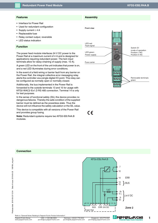
16-05-23 12:04D a t e o f i s s u e 2016-05-23189784_e n g .x m l14131571024 V DC9-12-8+11+BUSERR ConnectionAssembly•Interface for Power Rail•Used for redundant configuration •Supply current ≤ 4 A •Replaceable fuse•Relay contact output, reversible •LED status indicationFunctionThe power feed module interfaces 24V DC power to the Power Rail at a maximum current of 4A and is designed for applications requiring redundant power. The twin input terminals allow for daisy-chaining of supply (max. 10A).A green LED on the front of the unit indicates that power is on, and a red LED illuminates during error conditions.In the event of a field wiring or barrier fault from any barrier on the Power Rail, the integral collective error messaging relay alerts the controller via a single digital I/O point. This relay can be configured as normally open or normally closed.Additionally, the bus implemented in the Power Rail isforwarded to the outside terminals 13 and 15 for usage with KFD2-WAC2-Ex1.D RS 485 connection. Terminal 14 is only for test purposes.In the sense of functional safety (SIL) the device provides no dangerous failures. Thereby the safe condition of the supplied barrier must be defined as the powerless state. Thus the device will not influence the safety calculation or the SIL value.This device is compatible with all versions of the Power Rail and provides group fusing.Note: Redundant systems require two KFD2-EB.R4A.B modules.FeaturesFront view16-05-23 12:04D a t e o f i s s u e 2016-05-23189784_e n g .x mlSupplyConnection terminals 11+, 12-terminals 8+, 9-Rated voltage U n20 ... 30 V DCThe maximum rated operating voltage of the devices plugged onto the Power Rail must not be exceeded.Power dissipation ≤ 2.4 WOutputSupply Output current: ≤ 4 A Fault signal relay output: NO contactContact loading30 V AC/ 2 A / cos φ ≥ 0.7 ; 40 V DC/ 2 A Energized/De-energized delay approx. 20 ms / approx. 20 msFuse rating5 Arecommended maximum utilization of the fuse: 80 %Directive conformity Electromagnetic compatibilityDirective 2014/30/EU EN 61326-1:2013 (industrial locations)ConformityElectromagnetic compatibility NE 21:2006Degree of protection IEC 60529:2001Ambient conditions Ambient temperature -20 ... 60 °C (-4 ... 140 °F)Mechanical specifications Degree of protection IP20Mass approx. 100 gDimensions 20 x 119 x 115 mm (0.8 x 4.7 x 4.5 in) , housing type B2Mountingon 35 mm DIN mounting rail acc. to EN 60715:2001Data for application in connection with Ex-areasStatement of conformityTÜV 00 ATEX 1618 X Group, category, type of protection, temperature class ¬ II 3G Ex nA nC IIC T4Directive conformityDirective 2014/34/EU EN 60079-0:2012+A11:2013 , EN 60079-15:2010International approvals FM approval Control drawing 116-0160Approved for Class I, Division 2, Groups A, B, C, D; Class I, Zone 2, IIC UL approvalApproved for Class I, Division 2, Groups A, B, C, D; Class I, Zone 2, IIC CSA approval Control drawing 116-0160Approved for Class I, Division 2, Groups A, B, C, D; Class I, Zone 2, IIC IECEx approval IECEx UL 16.0051Approved for Ex nA nC IIC T4 Gc General information Supplementary informationStatement of Conformity, Declaration of Conformity, Attestation of Conformity and instructions have to be observed where applicable. For information see .16-05-23 12:04D a t e o f i s s u e 2016-05-23189784_e n g .x mlPower feed module KFD2-EB2The power feed module is used to supply the devices with 24 V DC via the Power Rail. The fuse-protected power feed module can supply up to 150individual devices depending on the power consumption of the devices. Collective error messages received from the Power Rail activate a galvanically-isolated mechanical contact.Power Rail UPR-03The Power Rail UPR-03 is a complete unit consisting of the electrical insert and an aluminium profile rail 35mm x 15mm. To make electrical contact, the devices are simply engaged.Profile Rail K-DUCT with Power RailThe profile rail K-DUCT is an aluminum profile rail with Power Rail insert and two integral cable ducts for system and field cables. Due to this assembly no additional cable guides are necessary.Power Rail and Profile Rail must not be fed via the device terminals of the individual devices!Accessories。
EI4 系列一体式 I O 用户手册

ASCON温度控制器M1中文说明书解读

ASCON spa via Falzarego 9/11 20021 博拉特 意大利(米兰) 电话: +39 02 333 371 传真: +39 02 350 4243 网址:http://www.ascon.it 邮箱:support@ascon.it温度控制器1/16德国标准 -48x48系列M1线用户手册•M.I.U.M1-4/04.07•编号J30-478-1AM1 IE通过ISO9001认证温度控制器1/16德国标准-48x48M1线对电气安全和电磁兼容的注释在安装控制器前,请先认真阅读下列指导。
第二类仪器,后面板安装。
控制器按照以下内容设计:电气设备规则根据欧洲共同体第93/68/EEC号指令修正的欧洲共同体第73/23/EEC号指令(设备、系统和安装)以及电气设备EN61010-1 :93 + A2:95中关于强制保护要求的规则。
电磁兼容规则根据欧洲共同体第n°92/31/EEC、93/68/EEC和98/13/EEC号指令修正的欧洲共同体第n089/336/EEC号指令,并遵守以下规则:射频排放规则:EN61000-6-3 : 2001 居住环境EN61000-6-4 : 2001 工业环境射频抗扰度规则:EN61000-6-2 : 2001 工业设备和系统让安装者了解其应遵守安全要求和EMC规则至关重要。
该设备不具备可供用户使用的部件,且需要使用专用设备并通过专业工程师来操作。
因此,用户不能轻易直接对设备进行维修。
为此,生产商可为客户提供技术援助和维修服务。
欲知详情,敬请联系最近的代理商。
所有关于安全和电磁兼容信息和警告都在注释侧面标明了标志。
目录1 安装 ..................................................................................................................... 第4页 2 电气连接 ............................................................................................................. 第8页 3 产品编码 ............................................................................................................. 第14页 4 操作 ..................................................................................................................... 第18页 5 自动调准 ............................................................................................................. 第28页 6 技术规范 . (29)(可选)指示专用主要通用输入单一动作资源 工作模式 单一动作 控制警告重新传输设置点 特殊功能通过自动选择模糊调整单次对焦自动调整单次对焦固有频率RS485通讯接口参数化监督1 安装只有合格人员才能进行安装在安装控制器前,请遵守该手册中的指令,特别是标有标志的安装防范,该标志与欧洲共同体关于电气保护和电磁兼容的指令有关。
NORDAC FLEX SK 200E 电机驱动器说明书
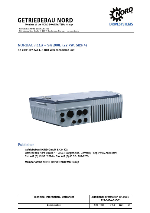
Getriebebau NORD GmbH & Co. KGGetriebebau-Nord-Straße 1 • 22941 Bargteheide, Germany • NORDAC FLEX – SK 200E (22 kW, Size 4)SK 200E-222-340-A-C-DC1 with connection unitPublisherGetriebebau NORD GmbH & Co. KGGetriebebau-Nord-Straße 1 • 22941 Bargteheide, Germany • / Fon +49 (0) 45 32 / 289-0 • Fax +49 (0) 45 32 / 289-2253Member of the NORD DRIVESYSTEMS GroupDocumentation – Additional Information SK 200E-222-340A-C-DC1 2 / 7TI 70_1901 - 0221Validity of documentThe following information applies for the following types of NORDAC FLEX series frequency inverters. • Frequency inverterSK 200E-222-340-A-C-DC1 (part number: 275137817)• Connection unitSK TI4-4-2xx-4-C-DC1 (part number: 275279914)Destruction of the frequency inverter through use of an incorrect connection unitIf the frequency inverter is not operated with the corresponding connection unit, this will result in overload of electrical components and thus to the destruction of the device.• Only operate the frequency inverter with the corresponding connection unit.The devices differ from standard devices basically in the permissible supply voltage and the connection terminals to be used for this purpose. The devices are based on the standard firmware of the NORDAC PRO SK 200E series.• The frequency inverter is to be used exclusively with the corresponding connection unit.• The connection unit is to be used exclusively with the corresponding frequency inverter.The following documents are therefore the basis for the device:1. BU 0200, edition 4920 (Part no.: 6072001)Safety information, hardware description, installation notes and software description for the basic device2. BU 0210, edition 1620 (Part no.: 6072101)Description of the POSICON function3. BU 0550, edition 1919 (Part no.: 6075501)for the description of PLC functionality4. and the following information identifying the differences of the device in comparison with BU 0200with regard to the hardware description and installation information.Documentation – Additional Information SK 200E-222-340A-C-DC1TI 70_1901 - 02213 / 71 GeneralThe following deviations from the manual apply.Chapter 1.6 Standards and approvalsThere is no approval according to UL, CSA, RCM or EAC as well as CE EX or EAC Ex !2 Assembly and installationThe following deviations from the manual apply.Chapter 2.3 Braking resistor (BR) Chapter removed.No braking resistor can be connected.Chapter 2.4.2 Electrical connection of the power unit Paragraph3. Mains cable connection: to terminals L1-L2/N-L3 and PE (depending on the device)is replaced by3. Mains cable connection: to terminals DC+ / DC- and PEDocumentation – Additional Information SK 200E-222-340A-C-DC14 / 7TI 70_1901 - 0221Chapter 2.4.2.1 Mains connection (L1, L2(/N), L3, PE) This chapter is replaced byChapter 2.4.2.1 Mains connection (DC+, DC-, PE)WARNINGElectric shockDangerous voltages can be present at the mains input and the motor connection terminals, even when the device is not in operation.• Before starting work, check that all relevant components (voltage source, connection cables, connection terminals of the device) are free of voltage using suitable measuring equipment. • Use insulated tools (e.g. screwdrivers). • DEVICES MUST BE EARTHED.Supply voltage connectionIncorrect DC supply connection results in destruction of the frequency inverter. • Observe correct polarityFuse protection must be provided by a suitable DC fuse (see technical data). For connection to or isolation from the mains, components (main switch or contactor) with suitable DC rating must be used. Isolation from or connection to the mains must always be carried out for all poles.InformationInput chokeFor improved EMC characteristics and in order to minimise the back-flowing current, an input choke can be incorporated into the mains supply cables. • Inductance: 0.3 to 0.5 mH • Nominal current: ≥ 50 AJumper positionThe jumpers for the line filters (2) must be set according to the figure (only jumpers on the right are set).CY = ONDocumentation – Additional Information SK 200E-222-340A-C-DC1TI 70_1901 - 02215 / 7Connection schemeChapter 2.4.2.3 Brake resistor (+B, -B) Chapter removed.3 Display, operation and optionsNo deviations4 CommissioningNo deviations5 ParametersNo deviations6 Operating status messagesNo deviationsDocumentation – Additional Information SK 200E-222-340A-C-DC1 6 / 7TI 70_1901 - 02217 Technical DataThe following deviations from the manual apply.Chapter 7.1 General dataFunction SpecificationPulse frequency 3.0 … 16.0 kHz, factory setting = 6 kHzPower reduction > 6 kHzAmbient conditions 3K4 IP66Hardware status EAAFirmware status V2.2 R0All other specifications remain unchanged.Chapter 7.2.2 Electrical data 400 V2) FLA – Full Load Current, maximum current for the entire mains voltage range as stated above3) FLA (S1-40°C)4) Fan cooling, temperature controlled ON= 55°C, OFF= 50°C,Run-on time if the 50°C limit is undershot and with the removal of the enable: 2 minutesDocumentation – Additional Information SK 200E-222-340A-C-DC1TI 70_1901 - 02217 / 78 Additional informationThe following deviations from the manual apply.Chapter 8.3.3 EMC of the deviceFigure 33, The wiring recommendation is to be applied analogously. • Mains connection: Instead of L1, L2/N, L3, now use DC+, DC- according to the labelling on the terminal strip • Braking resistor n/aChapter 8.4.4 Reduced output current due to low voltage Chapter removed.Chapter 8.5 Operation on the RCD Chapter removed.9 Maintenance and service informationNo deviations。
ESL-411L_数字线路保护测控装置说明书模板

ESL-411L©Copyright reserved目录1装置简介 (1)2技术指标 (1)2.1额定工作电源 (1)2.2额定交流数据 (1)2.3交流回路过载能力 (2)2.4功率消耗 (2)2.5出口触点 (2)2.6主要技术数据 (2)2.6.1过流一段、过流二段、过流三段保护 (2)2.6.2重合闸功能 (3)2.6.3后加速功能 (3)2.6.4低周减载功能 (4)2.6.5小电流接地选线及零序过流保护 (4)2.6.6过负荷保护 (5)2.6.7失压保护 (5)2.6.8遥测精度 (5)2.6.9遥信分辨率 (5)2.7绝缘性能 (6)2.7.1绝缘电阻 (6)2.7.2介质强度 (6)2.8冲击电压 (6)2.9抗干扰能力 (6)2.10机械性能 (6)2.11环境条件 (6)3装置结构 (7)4装置硬件 (7)4.1装置命名规则 (7)4.2装置重量 (7)4.3硬件说明 (7)4.3.1CPU主板 (7)4.3.2出口板 (8)4.3.3工作电源 (8)4.3.4人机对话板(MMI板)使用说明 (8)5保护原理 (12)5.1保护启动 (12)5.2低压闭锁方向过流保护功能 (12)5.3零序过流保护功能 (13)5.4PT断线监视及母线绝缘监察功能 (13)5.5小电流接地选线功能 (14)5.6过负荷保护 (14)5.7周减载功能 (15)5.8重合闸功能 (15)5.9失压保护功能 (16)5.10控制回路断线 (16)5.11遥测功能 (17)5.12遥信采集 (17)5.13遥控 (17)6安装调试 (17)6.1通电前检查 (17)6.2装置通电检查 (17)6.2.1装置带电检查 (18)6.2.2LCD显示检查 (18)6.2.3装置遥信输入回路检查 (18)6.2.4电流电压刻度值检查 (18)6.2.5通道系数检查 (18)6.3传动试验 (18)6.3.1手动合闸检查 (18)6.3.2手动跳闸检查 (18)6.4绝缘性能检查 (18)6.5定值输入 (18)7运行维护 (18)7.1装置投运前检查 (18)7.2保护动作信号 (19)7.3LCD显示 (19)7.4运行与维护 (19)8贮存保修 (19)8.1产品包装 (19)8.2运输条件 (19)8.3贮存条件 (19)8.4保修时间 (19)9供应成套性 (20)9.1随产品供应的文件 (20)9.2随产品供应的配套件 (20)10订货须知 (20)11附录 (20)附录1:ESL-411L状态字说明 (20)附录2:ESL-411L控制字说明 (22)附录3:ESL-411L软压板清单 (23)附录4:ESL-411L定值清单 (23)附录5:ESL-411L配置清单 (24)附录6:ESL-411L遥控说明 (26)附录7:ESL-411L通道系数定义 (26)附录8:ESL-411L遥信说明 (27)12附图 (28)附图1:ESL-411L模拟量输入原理图 (28)附图2:ESL-411L出口板原理图 (29)附图3:ESL-411L端子定义 (31)1装置简介ESL-411L数字线路保护测控装置是由北京易艾斯德科技有限公司自主研发生产的新一代数字保护测控装置,产品采用国际先进的DSP和表面贴装技术,工艺成熟可靠,适用于66kV及以下电压等级,是线路单元的间隔层设备。
- 1、下载文档前请自行甄别文档内容的完整性,平台不提供额外的编辑、内容补充、找答案等附加服务。
- 2、"仅部分预览"的文档,不可在线预览部分如存在完整性等问题,可反馈申请退款(可完整预览的文档不适用该条件!)。
- 3、如文档侵犯您的权益,请联系客服反馈,我们会尽快为您处理(人工客服工作时间:9:00-18:30)。
7
武汉力源信息技术有限公司
免费电话:800-880-8051
数据手册 DS-107-00024CN
电气指标:5V 电源
测试条件: V+=+4.5V到+5.5V,GND =0V,VINH=2.4V,VINL=0.8V(注 3),除非另有说明。
8
武汉力源信息技术有限公司
免费电话:800-880-8051
数据手册 DS-107-00024CN
注:3.VIN=使器件处于给定状态的输入逻辑电压 4.数据手册中使用了代数规则,负的最大值最小,正的最大值最大。 5. ΔRON=RON(MAX)-RON(MIN)。 6.平直率定义为规定模拟信号范围内,导通电阻的最大和最小值之间的差值。 7.漏电参数在高温下测得,在 25℃下有相关保证。 8.在任意两个开关之间。
14
武汉力源信息技术有限公司
免费电话:800-880-8051
数据手册 DS-107-00024CN
电源供电考虑
ISL43681 和 ISL43741 的结构是典型的 CMOS 模拟开关,因为它们有 3 个电源引脚:V+,V-,和 GND。 V+和 V- 驱动内部 CMOS 开关,决定它们的模拟电压极限值,因此模拟信号通路和 GND 之间没有连接。 不象用 13V 最大电源电压供电的其他模拟开关,ISL43681 和 ISL43741 的 15V 最大电源电压为 10%容差
开所有的信号通道。它还有一个锁存引脚,可锁住最后的开关地址。
接通电阻在 ± 5V 电源下,为 39Ω;± 3.3V 电源下,为 125Ω。每个开关都能够处理轨对轨模拟信号。
漏放电流在+25℃下只有 0.1nA,在+85℃下为 2.5nA。
使用 3.3V 或+5V 单电源,或 ± 5V 的双电源时,所有的数字输入有 0.8V 到 2.4V 的逻辑门限,以保证
最大结温(塑料封装)……………………………… 150℃ 最大储存温度范围 ……………………………… -65℃到 150℃ 最大引线温度(低温焊接 10s)………………………… 300℃
(仅限引线尖端)
注意:强度超出所列的极限参数可能导致器件的永久性损坏。这些仅仅是极限参数,并不意味着在极限条 件下或在任何其它超出推荐工作条件所示参数的情况下器件能有效工作。
静电释放额定值 HBM(每个 Mil-STD-883,依据 3015.7 标准)……… >2.5kV
工作条件
温度范围 ISL43681IR 和 ISL43741IR ……………………………… -40℃到 85℃
热信息
热阻(典型值, 注 2)
θJA(℃/W)
20 Ld 4 × 4 QFN 封装 ……………………………… 45
应用
电池供电,手提和便携式设备 通信系统 ——无线电收音机 ——电信基础结构 ——ADSL,VDSL 调制解调器 测试设备 ——医学超声波 ——心电图仪 ——磁共振成像 ——CT 和 PET 扫描器(MRI) ——自动测试设备 音频和视频转换 多种电路 ——+3V/+5V 数模转换器和模数转换器 ——抽样和保持电路 ——运算放大器增益转换电路 ——高频模拟开关 ——高速多路复用 ——积分复位电路
通过在输入端串联一个 1kΩ的电阻,逻辑输入很容易被保护(见图 9)。电阻限制了输入电流,使其 保持在引起永久破坏的门限之下,次微安输入电流在正常工作下产生一个无关紧要的电压降。
该方法不适用于信号通道的输入。给开关输入增加一个串联电阻阻扰了使用一个低RON开关的目的, 因此,两个小信号二极管能够与电源脚串联来为所有管脚提供过压保护(见图 9)。这些附加的二极管使模 拟信号的值限制在比V+低 1V,比V- 高 1V之间。低漏放电流性能不受这一方法的影响,但开关电阻可能 会增加,特别是在低电源电压下。
是同系列中最好的。 它的宽的带宽,非常高的断开隔离和串话干扰抑制同样有利于高频应用。
电源排序和过压保护
和所有的 CMOS 器件一样,适当的电源排序可保护器件免受可能使集成电路受到永久性损坏的过量输 入电流的冲击。接 V+和接 V-的所有的输入/输出管脚都包括 ESD 保护二极管(见图 9)。为防止二极管的 正向偏置,在输入信号前必须加上 V+和 V- ,且输入信号电压必须保持在 V+和 V- 之间。如果这些条件 不能满足,可采用下面两种保护方法之一。
武汉力源信息技术有限公司
免费电话:800-880-8051
数据手册 DS-107-00024CN
13
武汉力源信息技术有限公司
免费电话:800-880-8051
数据手册 DS-107-00024CN
详细描述
ISL43681 和ISL43741 多路复用器工作在 ± 2V到 ± 6V的双极性电源或 2V到 12V的单电源下,提供精
注:Intersil无铅产品采用特殊的无铅材料制成,模塑料/晶片的附属材料和100%无光泽锡盘引脚符合 RoHS标准,兼容SnPb和无铅低温焊接操作。Intersil无铅产品在无铅峰值回流温度中属于MSL级别分类, 完全满足和超过IPC/GEDEC JSTD-020的无铅要求。
武汉力源信息技术有限公司
免费电话:800-880-8051
数据手册 DS-107-00024CN
低电压,单/双电源,8合1多路复用器和差分4合1多路复用器
概述
Intersil ISL43681 和 ISL43741 是精密,双向模拟开关,配有 8 通道和一个差分 4 通道多路复用器/多路
信号分离器。它们工作在+2V 到+12V 的单电源,或 ± 2V 到 ± 6V 的电源下。它设有抑制管脚,可同时打
引脚图
2
武汉力源信息技术有限公司
免费电话:800-880-8051
真值表
数据手册 DS-107-00024CN
注:逻辑“0” ≤ 0.8V,逻辑“1” ≥ 2.4V,V+在 2.7V 和 10V 之间。”X”=无影响。
注:逻辑“0” ≤ 0.8V,逻辑“1” ≥ 2.4V,V+在 2.7V 和 10V 之间。”X”=无影响。 订购信息
LE , EN ,EN,NO,NC,ADD(注 1)…………………… -0.3 至((V+)+0.3V)
输出电压 COM(注 1)…………………………………………… -0.3 至((V+)+0.3V)
连续电流(任一终端)…………………………………… ± 30mA
峰值电流 NO,NC 或 COM
(脉冲 1ms,10%占空因数,最大值)………………… ± 100mA
V+和 GND 也为内部逻辑(因此设置数字开关点)和电平移位器供电。电平移位器将输入逻辑电平转 换为开关的 V+和 V- 信号,来驱动模拟开关门接线端。
逻辑电平门限
V+和GND为内部逻辑级供电,因此V- 对逻辑门限没有影响。该开关系列在V+电压范围为 2.7V到 10V 的情况下,可兼容TTL电平(0.8V和 2.4V)。12V下,VIH电平约为 3.3V。这仍比CMOS保证高电平输出所 需的最小电平 4V低,但噪声边缘减少了。为了达到 12V电源的最好结果,使用一个逻辑系列提供高于 4V 的VOH。
免费电话:800-880-8051
数据手册 DS-107-00024CN
电气指标: ± 5V 电源 测试条件: VSUPPLY= ± 4.5V到 ± 5.5V,GND =0V,VINH=2.4V,VINL=0.8V(注 3),除非另有说明。
5
武汉力源信息技术有限公司
免费电话:800-880-8051
模拟开关公共脚 模拟开关常开脚 地址输入脚 无内部连接
极限参数
V+到 V- …………………………………………………… -0.3V 至 15V 对 GND 的 V+ ……………………………………………… -0.3V 至 15V 对 GND 的 V- ……………………………………………… -15V 至 0.3V 输入电压
特点
完全适用于 10%容差的 3.3V,5V, ± 5V 和 12V 的电源 最大接通电阻(RON),Vs= ± 4.5V……………………………… 50Ω
最大接通电阻(RON),Vs=+3V………………………………… 155Ω
与信道匹配的RON,Vs= ± 5V…………………………………… <2Ω 低电荷注入,Vs= ± 5V…………………………………… 1pC(最大)
数据手册 DS-107-00024CN
电气指标:3.3V 电源
测试条件: V+=+3.0V到+3.6V,V- =GND =0V,VINH=2.4V,VINL=0.8V(注 3),除非另有说明。
9
武汉力源信息技术有限公司
免费电话:800-880-8051
数据手册 DS-107-00024CN
确的开关能力,双 5V电源下有低的导通电阻(39Ω)和高速的工作能力(tON=38ns,tOFF=19ns)。 它们设有抑制管脚,可同时打开所有的信号通道。它们还有一个锁存引脚,可锁住最后的开关地址。
器件特别适合于使用 ± 5V电源供电的应用。 ± 5V电源下,它的性能(RON,漏放电流,电荷注入等)
6
武汉力源信息技术有限公司
免费电话:800-880-8051
数据手册 DS-107-00024CN
电气指标:+12V 电源
测试条件: V+=+10.8V到+13.2V,GND =0V,VINH=4V,VINL=0.8V(注 3),除非另有说明。
注:1. NO,NC,COM,ADD,EN, EN 或 LE 上超过 V+或 V- 的的信号受内部二极管的钳制。限制正