FLUENT模拟齿轮转动
基于Fluent的齿轮泵内部流场动态模拟

基于Fluent的齿轮泵内部流场动态模拟XXX(XXXXXXXXXXXXXXXXXXXXXXXXXXXXXXXXXX)摘要:齿轮泵是液压传动及润滑系统中的常用部件,为了准确地捕捉泵内流场的变化,采用动网格技术对齿轮泵进行动态数值模拟,分析齿轮泵在齿轮旋转情况下的内部流场的变化。
关键词:齿轮泵;内部流场;动态模拟Dynamic simulation of flow field inside of gear pump based on FluentXXX(XXXXXXXXXXXXXXXXXXXXXXXXXXXXXXXXXX)Abstract: The gear pump is an important component in hydraulic transmission and lubrication system. In order to catch the variation of flow field inside of gear pump, the moving grid technology is used to dynamic simulate the flow in gear pump, and the flow variation inside of gear pump with gear rotating is analyzed.Key words: gear pump; inside flow field; dynamic simulation1 概述齿轮泵适用于输送不含固体颗粒和纤维、腐蚀性的润滑油或性质类似润滑油的其他液体,以及液压传动系统。
齿轮泵的内部流动对齿轮泵的性能有较大的影响,在齿轮泵的设计初期就应该考虑泵内结构对流动的影响,以便设计符合要求的齿轮泵。
齿轮泵的内部流场的动模拟为齿轮泵内部结构设计提供重要的参考数据,是现代齿轮泵设计的一项重要辅助手段。
由于齿轮泵内齿轮运动及工作介质流动的复杂性,其数值模拟工作比较复杂,国内对齿轮泵的模拟仅局限于流量模拟,没有进行详细的泵内流场模拟,国外对泵内流场模拟相对较多。
基于Fluent与ANSYS workbench的齿轮箱热固耦合温度场仿真案例
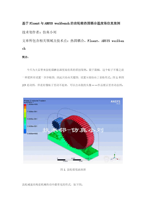
基于Fluent与ANSYS workbench的齿轮箱热固耦合温度场仿真案例技术邻作者:仿真小刘文章所包含相关领域及技术点:热固耦合、Fluent、ANSYS workben ch简介:今天为大家带来齿轮箱瞬态温度场仿真的原创案例。
限于篇幅,这个帖子不像之前一样把所有设置一步步贴图,因此只给出关键图,设置全部给出了表格形式。
图1和图23是动图,但是好像帖子里动不起来,可以点击我的头像——作品展示里有动态图。
图1齿轮箱甩油润滑齿轮减速结构是机械传动中最常见的形式,如下图。
图2齿轮箱结构由于齿轮之间存在摩擦,因此齿轮系统的温度场必须进行关注,以确保:齿轮结构没有过热(overheating)保证齿轮结构的完整性避免滑油过热引发的性能下降(粘度降低)及事故发生(如风机装置有可能油起火)进一步延伸的话,由温升引发的热应力是分析齿轮与齿轮轴,乃至轴承与壳体的热疲劳问题的必要计算条件。
这个问题另外开帖与大家探讨。
—————————————————————————————————正文:齿轮温度场涉及到摩擦学、传热学、机械传动理论和有限元分析等多学科领域的知识,是一个比较复杂的问题。
1969年,Blok.H阐述了热网络理论,其本质是考虑系统中各部分生热,在网络中用一个节点表示,每个节点表示每部分的平均温度。
通过整体分析得到要求的的各部分的温度值。
这种方法的缺陷在于,首先必须建立热阻、功率损失、对流换热系数计算模型,而这些参数不容易获得。
那么我们考虑用仿真的手段去求解这个问题。
我们首先来分析齿轮箱的结构,齿轮箱机械结构由壳体、端盖、大小齿轮、轴承、轴以及其他附件构成,我们首先要搞清楚分析的对象。
壳体的温度是否是我们关注的要点?在本例中不是,那么我们的分析对象就是壳体中的所有元素,壳体只作为仿真的外边界。
轴承和轴在仿真中的意义也不明显,因此我们都予以简化。
分析传热模型,齿轮摩擦生热是热源,这些热量通过几种方式传播:1.热传导——从齿缘往齿轮中心传导2.热对流——齿轮和润滑油,润滑油和空气,又称为共轭传热3.热辐射——温度不高,辐射量小可忽略因此,滑油和空气是传热的介质,必须在模型中考虑进去(事实上这部分传热达到91%)。
基于FLUENT的旋翼(螺旋桨)旋转仿真

基于FLUENT的旋翼(螺旋桨)旋转仿真本文主要通过动网格技术对旋翼旋转过程的气流现象进行仿真。
涉及到机构网格、非结构网格划分,网格组装,UDF应用,CFX-POST后处理等软件应用知识点。
希望能够给大家学习提供帮助。
由于时间紧迫,加上本人的水平有限,文中的不足之处请大家批评指正。
利用fluent对旋翼旋转进行仿真,通过仿真结果观察旋翼以1000rad/s的速度转动时的气流现象。
旋翼几何模型针对问题描述建立几何模型如图1所示,将整个计算域划分成固定域和旋转域。
网格的划分采用网格模型组装方法,固定域通过结构网格方法划分网格,旋转域包含旋翼曲面采用非结构网格方法建立相应的part 如图将上述几何模型保存为single.tin一、进行旋转域网格划分将parts里的名字为DOWN 、UP、DOWN_WALL、WALL的part删除,留下的几何图形即为包含旋翼的旋转域如图所示将上述几何模型保存为single_in.tin现在对旋转域进行网格划分,先生成旋转域的壳网格。
网格参数的设置如图所示生成的旋翼表面网格如图所示对网格质量进行检查,网格质量较好,quality质量指数在0.5以上。
对壳网格进行保存,为single_in_shell.uns。
单纯的壳网格并不能进行流动计算,接下来对旋转域进行体网格划分。
图中为切面处的体网格,按照下列参数对网格质量进行检查。
从上图中可以看出,网格质量在0.15以上,没有负网格产生。
保存网格为single_in.uns。
二、进行固定域网格划分打开开始保存的几何文件single.tin,将parts里的名字为PROPELLER的part删除,留下的几何图形即为不包含旋翼的固定域如图所示将模型另存为single_out.tin。
固定域结构简单,现在对其进行结构网格划分。
固定域Block划分及节点设置,如图所示。
进行网格预览,并检查网格质量。
所有网格Determinant2X2X2值大于0.5,大部分大于0.6。
基于Fluent的外啮合齿轮泵内部流场仿真分析

Science and Technology &Innovation ┃科技与创新2020年第24期·55·文章编号:2095-6835(2020)24-0055-03基于Fluent 的外啮合齿轮泵内部流场仿真分析*姚奇,沈仙法,季丰(三江学院机械与电气工程学院,江苏南京210012)摘要:为提高外啮合齿轮泵的使用寿命,减轻齿轮泵的困油和泄漏现象,利用Fluent 软件对外啮合齿轮泵的内部流场进行了仿真,研究了齿轮泵齿侧间隙为0.05mm 、0.1mm 和0.15mm 时对困油压力的影响,分析了转速为1000r/min 、2000r/min 和3000r/min 时齿轮泵内部速度流场分布。
结果表明,齿轮泵的侧向间隙越大,泄漏量越大,容积效率越低;齿轮泵转速越大,内泄漏越大,容积效率越低,流量脉动加大,液场流速增大。
研究成果为外啮合齿轮泵的设计改进提供了技术参考,具有一定的实践意义。
关键词:外啮合齿轮泵;流场;仿真分析;Fluent 中图分类号:TH137.51文献标志码:A DOI :10.15913/ki.kjycx.2020.24.0181引言外啮合齿轮泵是液压系统的重要动力元件,它因具有结构简单、维修方便、自吸能力强、对油液污染不敏感等优点而广泛应用在冶金、采掘机械、航空航天和深海探测等诸多领域。
但是,同时,它也存在着泄漏、困油和径向不平衡力等缺点。
针对这些缺点,国内外学者对其展开了研究,并取得了一定成果。
李志华等运用数学模型的方法对齿轮泵进行优化设计[1]。
冀宏等使用Fluent 和Pro-E 软件对外啮合齿轮泵的径向力进行了数值计算,比较了卸荷槽改进前后的外啮合齿轮泵径向力后认为合理的卸荷槽设计可以使外啮合齿轮泵的径向力大大降低[2]。
周雄等通过大量的数值计算,求得间隙与泄漏之间的相对应关系,得出最佳的理论间隙[3]。
李金鑫等利用Matlab 软件研究了壳体参数对于泄漏的流量的影响[4]。
基于FLUENT的齿轮成形磨削气液两相流仿真分析

机械与动力工程河南科技Henan Science and Technology总第874期第3期2024年2月基于FLUENT 的齿轮成形磨削气液两相流仿真分析尹铭禹 杨佳兆 杜征征 邢 波 杨思源 杨 敏(南京工程学院工业中心,江苏 南京 211167)摘 要:【目的】针对齿轮磨削加工中冷却效果不佳,表面液流量少的问题进行研究。
【方法】设定不同的砂轮转速对磨削气流场进行仿真分析。
在液流场中使用VOF 气液两相流模型对不同喷嘴位置进行仿真模拟。
【结果】结果表明:砂轮旋转带动周围气体形成返回流,阻碍射流进入磨削加工区域;砂轮转速30 m/s 流体速度比砂轮转速20 m/s 时高50%,能够满足磨削加工需求且返回流强度适中;距离齿轮表面垂直距离40 mm 的喷嘴位置,能更好地将磨削液喷射至磨削区域,冷却效果最优。
【结论】经过上述仿真分析可得出最佳的砂轮转速和喷嘴位置,对实际加工中节能降耗有一定的指导意义。
关键词:齿轮;气流场;气液两相流;仿真模拟中图分类号:TP391.9 文献标志码:A 文章编号:1003-5168(2024)03-0018-04DOI :10.19968/ki.hnkj.1003-5168.2024.03.004Simulation Analysis of Gas-liquid Two-phase Flow in Gear Forming Grinding Based on FLUENTYIN Mingyu YANG Jiazhao DU Zhengzheng XING Bo YANG Siyuan YANG Min(Industrial Center ,Nanjing Institute of Technology ,Nanjing 211167,China )Abstract: [Purposes ] This paper conducts the research on the problem of poor cooling effect and low sur⁃face liquid flow in gear grinding. [Methods ] The grinding flow field was simulated by setting different grinding wheel speed. The VOF gas-liquid two-phase flow model is used to simulate different nozzle po⁃sitions in the liquid flow field. [Findings ] The results showed that the rotation of the grinding wheel drove the surrounding gas to form a return flow, which prevented the jet from entering the grinding pro⁃cessing area. The fluid speed of the 30 m/s grinding wheel is 50% higher than that of the 20 m/s grinding wheel, which can meet the requirements of grinding processing and the return flow strength is moderate.The nozzle position of 40 mm vertical distance from the gear surface can better spray the grinding fluid to the grinding area, and the cooling effect is optimal. [Conclusions ] The optimal grinding wheel speed and nozzle position can provide certain guiding significance for the energy saving and consumption reduction in the actual processing.Keywords: gear; flow field; gas-liquid two-phase flow; simulation0 引言在齿轮磨削加工中,砂轮与齿轮经过滑擦、耕犁、切削三个阶段会产生大量的热,可能会引发齿轮表面烧伤、裂纹、应力集中等损伤[1-2]。
基于Fluent的外啮合齿轮泵内部流场仿真计算

flow field characteristics of the gear pump are solved in Fluent, and the theoretical calculation results are in agreement with
each other to verify the correctness of the theoretical calculation. The results show that the maximum static pressure appears
机械工程师
MECHANICAL ENGINEER
基于Fluent的外啮合齿轮泵内部流场仿真计算
聂瑞, 潘福星, 郭伟 (合肥工业大学 机械工程学院,合肥 230000)
摘 要:建立了CB-B63系列外啮合齿轮泵内部流场的CFD模型,在Fluent中求解出了齿轮泵的内部流场特性,与理论计算
结果较吻合,验证了理论计算的正确性。得出了内部流量的压力分布云图,结果表明,最大静压出现在轮齿的啮合点附近,与
optimization of the gear pump.
Keywords: gear pump; internal flow field; CFD model; simulation calculation
0引言 齿轮泵是三大液压泵(齿轮泵、柱塞泵、叶片泵)的一
种,历史最悠久。齿轮泵的主要特点是结构简单,制造方 便,维修容易,工艺性好,价格低廉,体积小,重量轻。其主 要缺点是流量和压力脉动大,噪声较大,存在径向不平衡 力,效率低,被广泛地应用于机械制造、汽车、航空航天等 行业[6]。
near the meshing point of the gear, which is in accordance with the actual engineering. The hydrodynamic characteristics of
udf函数齿轮
UDF函数是一种强大的工具,它允许用户自定义并模拟特定的机械运动方式,如齿轮转动。
通过编程的方式,UDF函数可以计算和控制齿轮的转动角度和速度,从而模拟出真实的齿轮运动。
在ANSYS软件中,你可以编写UDF函数来模拟齿轮转动,具体步骤如下:首先需要编写UDF程序描述齿轮的运动,然后导入到Fluent软件中,最后给流体域设定UDF的运动。
此外,UDF在Fluent中的功能远不止于此。
除了能用于模拟齿轮转动,UDF还可以显著增强Fluent的功能。
例如,你可以自定义边界条件、材料特性、表面和体积反应速率、用户定义标量(UDS)、传输方程中的源项、扩散系数函数等。
应用FLUENT进行旋转机械仿真分析的教程
Axial machines
Flow through the machine is (in general) aligned with the axis of rotation Examples: propellers, axial fans/compressntrifugal machines
Flow through the machine is (in general) perpendicular to the axis of rotation Examples: liquid pumps, centrifugal fans/compressors, radial turbines
rotating components propeller, compressor/turbine blade, radial impeller, etc.
Single rotating reference frame (SRF) Multiple rotating reference frame (MRF) Mixing plane Sliding mesh
Present details on modeling rotating machinery problems using Fluent
基于FLUENT的多回路泵流场数值模拟
K e w o ds Mu t- e rP m p;Re e s gn e i y r : li g a u v re En i e rng;F LUENT ;M o i g Grd vn i
在大 型和高精 密 数控 机 床 导轨 润 滑 系统 中 , 体 流 静压 润滑 系统通过 静压 支 承 消 除机 床 导轨 的爬行 , 保
l 多 回路 泵 数值 模 拟 的前 处 理 J
本 文采用 最 简单 的多 回路 泵 模 型—— 三 齿轮 泵 , 多 回路泵 转速 为 4 5 rmi, 9 / n 中心轮 为 逆 时 针转 动 , 齿 轮为标 准 渐 开 线 圆柱 齿 轮 , 模 数 为 2 mm, 数 为 其 齿
多个泵 的使 用性 能。为准 确掌握 多 回路泵 内部流 场 变 化 , 用 F U N 运 L E T软 件 中 的动 网格 技术 对 多
回路泵 进行流 场动 态数值 模拟 , 析 多回路泵 在齿 轮旋 转情 况 下 的 内部 流 场变 化 , 分 从而 为 多 回路泵
的逆 向设计和 结构优 化奠 定基础 。 关键词 : 回路 泵 多 逆 向设计 FU N L E T 动 网格
mu —g a mp,t o i g g i e h oo y i le ts fwa e i s d t u rc ly smu ae t e f w hi e rpu hem v n rd tc n l g n fu n o t r s u e o n me ial i l t h o l
Nu me ia m ua in o lw il fM ut Ci utPu D Ba e 1 F UENT r l c Si lt fFo Fed o l— r i o i c m s d 03 L
Fluent理论手册(2)—旋转坐标系
而在转动子区域中的流动情况则有 2.2.1 节:转动参考系方程所描述。 在两个子区域之间的边界, 一个子区域控制方程中扩散项及其他项需要相邻 子区域的速度值。ANSYS FLUENT 强制保持绝对速度的连续性,以提供一个正 确的邻接速度值。 (此方法与混合面模型不同,混合面模型采用圆周平均技术) 。 当采用了相对速度表达式,则每一个子区域均使用相对运动计算。速度及速 度梯度使用方程 2.3.1 将运动参考系转换至惯性坐标系。 对于平移速度 ,则有 = +( )+ (2.3.1)
如果旋旋转速度不是是常方程将包含含一些anssysfluennt不包含的额外项尽管它们可能数变换后的方通过过使用用户自定义函数数添加至源注意到在具有有恒定转速速的运动参考考系中同同样可以采采用瞬态模拟拟
2 旋转参考系流动
本节主要描述旋转参考系流动模拟的数学背景。以下章节包含的内容包括: 2.1:介绍 2.2:旋转参考系流动 2.3 多旋转参考系流动
域的分解面上, 使用一个局部参考系将一个区域中的流动变量进行通量计算并转 换到相邻的区域。关于 MRF 分界面格式将在 2.3.1 节:MRF 分界面格式中进行 详细讲述。 应当注意到 MRF 方法不会使相邻的两个运动区域间产生先对运动(可能是 运动或静止) ;用于计算的网格依然是固定的。这类似于在制定位置固定运动部 分的运动且观察该位置瞬间流场。 因此, MRF 方法常常又称之为 “冰冻转子法” 。 尽管 MRF 方法是一个近似方法,但是对于许多应用提供了一个可信的流动 模型。例如,MRF 模型可用于转子与定子耦合相对较弱的透平机械问题中,以 及一些运动与静止区域截面间流动相对简单的问题求解。例如在混合槽中,当叶 片与挡板间的相互作用相对减弱时,大尺度的瞬态效应并不明显,此时可以使用 MRF 模型。 使用 MRF 模型可以为瞬态滑移网格计算提供一个较好的初始条件。在一些 转子与静子之间相互作用很强烈时,不能使用 MRF 模型,此时只能单独使用滑
- 1、下载文档前请自行甄别文档内容的完整性,平台不提供额外的编辑、内容补充、找答案等附加服务。
- 2、"仅部分预览"的文档,不可在线预览部分如存在完整性等问题,可反馈申请退款(可完整预览的文档不适用该条件!)。
- 3、如文档侵犯您的权益,请联系客服反馈,我们会尽快为您处理(人工客服工作时间:9:00-18:30)。
NUMERICAL SIMULATIONS OF UNSTEADY OIL FLOWS IN THE GEAR-BOXES
Frantisek LEMFELD*, Karel FRAŇA**, Jiří UNGER*** *Technical University of Liberec, Department of Power Engineering Equipment Studenstká 2, 46117, Liberec 1, Czech Republic Phone: (+ 420)485353434, Fax: + 420485353644, E-mail: frantisek.lemfeld@email.cz **Technical University of Liberec, Department of Power Engineering Equipment Studenstká 2, 46117, Liberec 1, Czech Republic Phone: + 420485353436, Fax: + 420485353644, E-mail: karel.frana@seznam.cz ***Technical University of Liberec, Department of Power Engineering Equipment Studenstská 2, 46117, Liberec 1, Czech Republic Phone: + 420485353405, Fax: + 420485353644, E-mail: jiri.unger@tul.cz This paper deals with the behavior of oil in the gear-box. For numerical simulations, the commercial software Fluent was used for relatively complicated problems of the two-phase unsteady turbulent flow. First of all, problems are focused on simplified models of one gear and set of gears, then finally on the model of complete gear-box. These cases are solved as unsteady problem - computation leads from start time, where oil pool is in calm, to the stable regime, where oil pool is in balance.The numerical study is consisted of several cases; run-up cogwhell or set of gears with the calm pool of oil, run-up with changes of oil pool sway, influence of viscosity changes on oil flows inside gear-box and run-up complete gear-box with calm pool of oil. Keywords: numerical simulation, oil flows, multiphase flow, gear-box
t = 0.5 s
t=1s
t=2s
t=5s
Figure 4a to 4d : Time procedure for single gear
As we can see from mentioned figures, run-up of cogwheel has influence to splashing of oil around gear-box. Initial amplitude of oil pool, caused by start, becomes stable after time as a splashing himself. In time t = 5 s doesn't happen any changes in the flow and we can say that this state we can call the steady state flow. 3.2 Set of gears – the calm pool of the oil After simulation of single gear, the set of gears was considered. Because mathematically modeled roughness do not involved influence of ejecting oil in place of cogwheels interaction, approximate volume flux of oil was calculated and the distance of cogwheels was modified to fit with this calculation. During computation was necessary to use lower value of the time step then in case of single gear. Following figures show progression of oil flow from start state to stable state of flow (Fig.5a to Fig.5d).
1INTRODUCTION The subject of this study is a numerical simulation of incompressible unsteady oil flows in gear-boxes [4]. First of all this common technical problem involves removal of heat from gear set. Heat is generated on the surface of gears in consequence of mutual friction meshing cogs. The cooling is done by the oil film which simultaneously decreases friction effect on the surface of the gear. Lubrication is solved by the waiding one of the gears in oil bath. Insufficient removal of heat leads to increasing temperature in the oil bath with changing material properties of oil. This leads to decreasing capability reduce friction. The increasing friction increases heat and backward effect is change of temperature in oil bath. Throwing of oil from the wading gear could be used for lubrication of bearings by force of intake area placed in the top of the gear-box. The problem is composed by the oil and surrounding air. These two components create two-phased system. Numerical simulation is performed by the commercial software Fluent. First of all, problems are studied on the simplified model of one gear with spiral gearing. The gear wades with the constant surface speed in the oil pool and effect of changing separate parameters with influence on behavior of the two-phased compound oil-air is observed. In the next step set of gears is involved into calculation. Set of gear is composed from main gear, which wades again in the oil pool with the constant speed and from the second gear, which serves to transmition torque and has no contact to the oil pool. Finally, the complete model of the gear-box is presented. 2 SOLVING METHOD Because reflect real cogs is relatively difficult for the solution, general influence of gearing is replaced by modeling roughness height, which corresponds to height of real cogs. The numerical simulation is realized by the Finite Volume Method (FLUENT) [1]. Implicit scheme for the time discretization is supposed. Twophased model (oil-air) is solved by Volume of Fluid (VOF) model with scheme Geo Reconstruct [2]. For cases of turbulent flows the statistic RANS model k-ω Standard is used [3]. Boundary conditions for all geometry in model are set to be „wall“ [4,7]. Parameters such as rotation movement and roughness height