Dell Compellent 存储用户手册
Dell Storage Center SC4020 存储系统 用户手册
SC4020 存储系统
用户手册
注、小心和警告
注: “注”表示可以帮助您更好地使用计算机的重要信息。 小心: “小心”表示可能会损坏硬件或导致数据丢失,并说明如何避免此类问题。 警告: “警告”表示可能会造成财产损失、人身伤害甚至死亡。
版权所有 © 2015 Dell Inc. 保留所有权利。 本产品受美国、国际版权和知识产权法律保护。 Dell™ 和 Dell 徽标是 Dell Inc. 在美国和 / 或其他管辖区域的商标。所有此处提及的其他商标和产品名称可能是其各自所属公司的商标。 2015 ......................................................................................................................... 24 故障转移行为..................................................................................................................................24 多路径 IO........................................................................................................................................24
2 连接前端................................................................................................................ 20
DELL官方服务器内存安装手册及注意事项
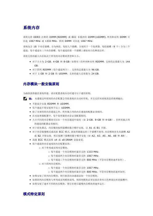
系统内存系统支持DDR3 注册的DIMM (RDIMM) 或ECC 非缓冲的DIMM (UDIMM)。
单列和双列DIMM 可以是1067 MHz 或1333 MHz,四列DIMM 可以是1067 MHz。
系统包含18 个内存插槽,分为两组,每组九个插槽,分别用于一个处理器。
每组插槽(9 个)分为三个通道,每个通道有三个内存插槽。
每个通道的第一个插槽上都标有白色释放拉杆。
系统支持的最大内存取决于所用的内存模块类型和大小:•对于大小为2-GB、4-GB 和8-GB(如果有)的单列和双列RDIMM,支持的总量最大为144 GB。
•对于四列RDIMM(每个通道两个),支持的总量最大为96 GB。
•对于1 GB 和2 GB 的UDIMM,支持的最大总容量为24 GB。
内存模块一般安装原则为确保获得最佳系统性能,请在配置系统内存时遵守以下通用原则。
注:未遵循这些原则的内存配置会导致系统在启动时停机,并且无任何系统消息的视频输出。
•不能混合安装RDIMM 和UDIMM。
•每个通道不得安装两个以上UDIMM。
•除了未使用的内存通道之外,所有被占用的内存通道的配置必须相同。
•在双处理器配置中,每个处理器的内存必须配置相同。
•大小不同的内存模块可以在一个内存通道中混用(如2-GB、8-GB 和4-GB),但所有被占用的通道的配置必须相同。
•对于优化器式,内存模块按照插槽的数字顺序安装,以A1 或B1 开始。
•对于内存镜像模式或高级ECC 模式,离处理器最远的三个插槽不使用,内存模块首先从插槽A2 或B2 开始安装,然后按剩下插槽的数字顺序安装(如A2、A3、A5、A6、A8 和A9)。
•高级ECC 模式需要x4 或x8 DRAM 设备宽度。
•每个通道的内存速度因内存配置而异:o对于单列或双列内存模块:o每个通道一个内存模块时最多支持1333 MHz。
o每个通道两个内存模块时最多支持1067 MHz。
o每个通道三个内存模块时最多支持800 MHz(不管内存模块速率如何)。
戴尔易安信 FS8600 网络附加存储 (NAS) 网络最佳实践指南说明书
Dell Compellent FS8600 Network-Attached Storage (NAS) Networking Best Practices GuideDell Compellent Technical Solutions GroupJuly 2013THIS BEST PRACTICES GUIDE IS FOR INFORMATIONAL PURPOSES ONLY, AND MAY CONTAIN TYPOGRAPHICAL ERRORS AND TECHNICAL INACCURACIES. THE CONTENT IS PROVIDED AS IS, WITHOUT EXPRESS OR IMPLIED WARRANTIES OF ANY KIND.© 2013 Dell Inc. All rights reserved. Reproduction of this material in any manner whatsoever without the express written permission of Dell Inc. is strictly forbidden. For more information, contact Dell.Dell, the DELL logo, and the DELL badge are trademarks of Dell Inc. Microsoft® and Windows® are either trademarks or registered trademarks of Microsoft Corporation in the United States and/or other countries. Other trademarks and trade names may be used in this document to refer to either the entities claiming the marks and names or their products. DellTable of Contents1Preface (2)1.1Audience (2)1.2Purpose (2)1.2.1Disclaimer (2)1.3Customer Support (2)2Introduction (3)2.1FS8600 networks (3)2.2FS8600 Internal Network (4)2.3FS8600 Primary Network (Client network) (4)3Network Switches Configuration (5)3.1Internal Switch Configuration (5)3.2Primary Switch Configuration (6)4Load Balancing (9)4.1Flat Network Configuration (9)4.2Routed Network Configuration (10)4.3Routed Network and Static Routes (11)To add a static route via the FS8600 CLI run the following command: (11)5Additional Subnets (12)5.1Additional Subnets (12)6Network Services (13)6.1NTP (13)7Network Security (14)7.1Firewalled Environments (14)8Additional Resources (17)Document Revisions Table 1: Document revisions1Preface1.1AudienceThe audience for this document is intended to be systems, networking, storage or backup administrators who are responsible for the day-to-day management responsibilities of a Dell Compellent FS8600 environment.Proper management of an FS8600 requires administrators or teams of administrators capable of managing and configuring enterprise-class Fibre Channel SAN and Ethernet networks, any enterprise-grade backup software intended to be used, the Dell Compellent Storage Center itself, as well as general purpose NAS administration.1.2PurposeThe purpose of this document is to cover specific implementation concepts or specifics related to the Dell Compellent FS8600 networking environment. It is not intended to be a primer or Dell Compellent FS8600 introductory resource for any of the subject matters involved, and it assumes at least introductory knowledge of many of the subjects covered in this document.This document should be used in conjunction with other Dell Compellent resources, such as the Dell Compellent Storage Center Connectivity Guide, FS8600 Admin Guide and Hardware Manual, Enterprise Manager 6 User Guide, or any other available documentation resources.1.2.1DisclaimerThe information contained within this best practices document is intended to provide general recommendations only. Actual configurations in customer environments may vary due to individual circumstances, budget constraints, service level agreements, applicable industry-specific regulations, or other factors. Configurations should be tested before implementing them in a production environment.1.3Customer SupportDell Compellent provides live support at 1-866-EZSTORE (866.397.8673), 24 hours a day, 7 days a week, 365 days a year for current customers. For additional support, email Dell Compellent at **********************. Dell Compellent responds to emails during normal business hours.2Introduction2.1FS8600 networksThe FS8600 utilizes three separate logical networks and two physical network segments to achieve maximum performance and security.∙Internal Networko Interconnecto Management∙Primary Network (Client Network)Figure 1: FS8600 networks diagram2.2FS8600 Internal NetworkThe interconnect network’s role is to provide communication between the cluster controllers to enable internal data transfer and heartbeat mechanism while maintaining low latency and maximum throughput.The interconnect segment is comprised of redundant gigabit Ethernet (1GbE) switches or10GbE (depending on a model purchased) with dual connection to each controller creating a fully redundant mesh.In one appliance configuration the interconnect network is comprised of two back to back links. To achieve full high-availability and future easy scalability it’s recommended to use redundant external switches.The management network’s role is to provide internal logging, syslog mirroring and in some cases option for remote access.2.3FS8600 Primary Network (Client network)The “primary network”, also known as the client network, connects the FS8600 system to the customer network via gigabit Ethernet or 10GbE (depending on a model purchased) multiple ports.The “primary network” provides access to data from NFS and CIFS clients and also access to the NAS administration virtual IP (VIP).3Network Switches Configuration3.1Internal Switch ConfigurationThe FS8600 requires the internal network switch configuration to support the following configuration:VLANThe interconnect network must live on a dedicated VLAN that is isolated from all other traffic and solely purposed for an individual cluster’s interconnect traffic. This VLAN must be untagged on all switch ports connected to the FS8600 interconnect connectivity ports. MTUAll switch ports connected to FS8600 interconnect connectivity ports must be “enabled” for Jumbo Frames (MTU equal to or greater than 9000).Spanning TreeSpanning tree must be “disabled” for all FS8600 interconnect ports. For many network vendor implementations, this will be called “portfast” or “edge” in the switch configuration semantics.Flow ControlThe FS8600 requires that all switch ports connected to the FS8600 interconnect interfaces have flow control “enabled”.The following is an example of how to configure Dell Force10 switches and Dell PowerConnect series (the same commands are applied to Dell PowerConnect series)3.2Primary Switch ConfigurationThe FS8600 requires the primary network switch configuration to support the following configuration:VLANThe FS8600 primary network is VLAN-aware, meaning it is capable of understanding and communicating with VLAN tagged Ethernet frames, allowing it to address multiple networks across multiple VLANs at a time.VLAN TaggingIf only tagged VLANs will be used for management and data, the FluidFS controllers need to be able to communicate with each other on the Client Network using untagged traffic. In other words, even if there is not a subnet configured to use untagged traffic, the switch must still allow untagged traffic/packets to pass. Blocking untagged traffic can cause issues with FluidFS during maintenance activities such as service pack upgrades, and controller replacement.The switch must be configured properly in its present state, otherwise the untagged and/or tagged VLAN would not be accessible.On Dell PowerConnect switches, this correlates to setting all of the frontend network ports to general mode, and then allowing the specific VLAN tags that are to be allowed to pass through.On Force10 switches, this correlates to using hybrid port mode. General mode (Dell PowerConnect) and hybrid mode (Dell Force10) will permit untagged traffic to pass through in addition to the tagged VLANs you specifically allowed. DO not use trunk mode, as trunk mode will only pass tagged traffic, and will disallow untagged traffic.MTUThe FS8600 primary network supports Ethernet jumbo frames.Environments can expect a degree of performance improvement, particularly where throughput is concerned.To change the MTU value (Defaults is set to 1500) on the cluster from the FS8600 CLI, run the following command:Flow ControlIt is recommended, but not required, that all switch ports connected to the FS8600 “p rimary network” interfaces have flow control “enabled”.For more information regarding flow control and Storage Center, consult any Copilot Support Tech Alerts for the Storage Center configuration in question.Switch TopologyAn FS8600 appliance or cluster can only be as highly available or high performing as the switch infrastructure supporting it. Architecturally, three guiding principles can be used to construct a best practice switch connectivity topology:•Avoid any single points of failure•Ensure sufficient inter-switch throughput•Make every client connectivity port in an FS8600 cluster available to any potential clientALB and LACP ModeAn FS8600 appliance equipped with multiple network interface cards are bonded to sustain seamless link failure.FS8600 supports two bonding modes:∙Adaptive Load Balancing (ALB)∙Link Aggregation Control Protocol (LACP)The default bonding mode for the FS8600 is ALB which requires no switch configuration and exposes all bonded MAC addresses.For LACP, some switch configuration is required and only a single MAC address is exposed. The main benefit of using LACP in FluidFS is to reduce the number of required VIPs while maintaining efficient load balancing.Setting up LACP modeWhen setting LACP you will need to perform the following configuration changes:∙In FluidFS, set one primary network VIP per FS8600 controller.∙In FluildFS, set up the bonding mode to “LACP”.∙In the “primary network” switch, all switches must be stacks and define one LACP trunk per FS8600 controller.Figure 2: FS8600 LACP configuration.To change the default bonding mode from ALB to LACP from the FluidFS CLi:4 Load BalancingLocal Production SiteKATANA_11DNS server ApplicationserverFigure 3: FS8600 in a routed network diagram 4.1 Flat Network ConfigurationIn case of a flat network, meaning there are no Layer 3 switches or routers between the FS8600 and the clients on the primary network, the FS8600 will use an internal ARP-based load balancing mechanism.To achieve load balancing across multiple interfaces, the system uses a virtual IP and proxy ARP. This workload balancing method supports both inbound and outbound workloads.The proxy-ARP protocol enables a host to provide ARP responses on behalf of other hosts. In order to support this, the destination hosts need to be configured with the proxy IP address, but should not answer broadcast ARP requests for that address. The system uses arp-filter and arp-tables to “hide” the proxy address so unicast ARP and other traffic are still served.To verify that clients connecting to the FS8600 are balanced across all system controllers from the FS8600 CLI, run the following command:To verify a specific client connection to the FS8600, from the FS8600 CLI, run the following command (you will need to provide the client IP and the virtual IP used):4.2Routed Network ConfigurationSince ARP load balancing is only able to balance local network clients, the FS8600 utilizes DNS load balancing to balance clients connected across Layer 3 switches and routers.In essence the FS8600 storage system will serve several virtual IP addresses, based on the number of interfaces attached to the client network. The virtual IP addresses are distributed and balanced among the nodes and interfaces.The administrator defines these addresses as a round-robin group in the DNS server in the site. Clients use DNS lookup and thereby are balanced across all of the available nodes and NICs.When implementing a round robin DNS system, it is important to understand the caching relationships of all subsequent DNS systems between the round robin DNS server and the clients.For example, if ns0.local and ns1.local are configured for Round Robin DNS but clients use ns0.office.local as their primary DNS target, ns0.office.local could possibly poll ns0.local to satisfy the request, but then cache the request and return the same value to the next client, hence removing the benefit of implementing Round Robin DNS. Some environments may see a benefit in keeping a short TTL value for the relevant DNS records for added overall flexibility.When allocating IPs and creating “A” record pools for round robin DNS, there should be at a minimum as many IPs and associated “A” records as there are interfaces in the FS8600 cluster.4.3Routed Network and Static RoutesRouted networks provide an opportunity to enhance performance through a feature called static routes. This feature allows you to configure the exact paths in which the FS8600 storage system communicates with various clients on a routed network.To add a static route via the FS8600 CLI run the following command:5Additional Subnets5.1Additional SubnetsThe FS8600 is capable of supporting or living on large numbers of separate or distinct networks, also referred to as subnets. This can be beneficial for reasons such as consolidating established or legacy file servers, as well as following best practices for providing dedicated resources to specific client groups or environments.NDMP backups and replication should also be isolated to a dedicated network, and it is also suggested that where possible, networks should be isolated in a one to one fashion with VLANs.To add additional subnets you will need the following information:∙Subnet mask∙VLAN information, if applicable∙Private IPs – one IP per FS8600 controller∙Public IP – will be used as Virtual IP (VIP)6.1NTPThe FS8600 can use the NTP to poll time information from authoritative outside sources. Generally, it is recommended that a minimum of two sources be used. Three or more sources is the suggested configuration.For FS8600 environments that will be integrated with Active Directory, the NTP sources should be the Active Directory domain controllers for the domain in question.To configure the time server for the Active Directory environment please refer to the following link:/en-us/library/cc784800%28v=WS.10%29.aspxCluster QuorumIn the event that both the configured gateway and DNS hosts are unreachable, the ability to reach the configured NTP hosts is used as a cluster quorum voting mechanism. Because this mechanism is used in the event that DNS is unreachable, at least one of the time servers should be configured by IP as opposed to DNS.7.1Firewalled EnvironmentsMany enterprise organizations have various layers of security within their network, often at their border, across different branches and work groups. Firewalls are used to implement access restrictions and Individual rulesWhen deploying Dell F8600 in a firewalled environment we need to make sure that specific ports are allowing traffic.The list of ports are divided to two groups:∙Enterprise Manager and Data Collector ports∙FluidFS portsData Collector Inbound PortsData Collector Outbound PortsEnterprise Manager Client PortsFluidFS Basic PortsFluidFS Additional Ports (Depends on NAS environment and services):8Additional ResourcesBelow are some links to additional resources:Dell Compellent Documentation∙Dell Compellent Replay Manager 7 Administrator's Guide ∙Dell Compellent Enterprise Manager 6.3 Users Guide∙Dell Compellent Storage Center 6.3 Users Guide。
DellCompellent存储用户手册
Dell Compellent用户手册Contents第一章存储管理基本操作 (6)系统信息 (6)IP地址 (6)拓扑 (7).. 7一、系统登录 (7)二、逻辑卷管理 (9)1、创建卷文件夹 (9)2、创建一个逻辑卷 (9)三、服务器管理 (12)1、创建服务器文件夹 (12)2、创建一个服务器 (12)3、绑定HBA卡或网卡(iSCSI方式) (13)四、逻辑卷映射服务器 (14)1、映射LUN (14)2、识别LUN (15)五、持续数据保护(数据即时回放,Data Instant Replay) (16)1、创建Replay Profiles (16)2、将Replay Profile应用至数据卷 (18)五、逻辑卷模板(Storage Profiles) (19)第二章主要功能介绍 (21)一、高级精简配置(Dynamic Capacity) (21)二、保护点恢复 (23)第三章MPIO软件 (25)对于Windows 2008 (25)对于Linux系统 (27)对于AIX操作系统 (28)对于VMW ARE (28)对于SUN主机 (29)第四章Compellent存储设备管理 (29)一、开关及步骤 (29)1.关机步骤 (29)2.开机步骤 (31)二、软件监控 (31)1.登入图形界面 (31)2.系统状态监控 (32)3.空间使用监控 (32)4.硬件状态监控 (33)5.存储后端连线图 (34)三、硬件监控 (34)1.系统状态指示灯 (34)2.控制器电源指示灯 (34)3.SAS磁盘箱状态指示灯 (34)4.SAS磁盘箱电源状态指示灯 (35)5.SAS盘箱IO模块状态指示灯 (35)第五章测试 (37)一、存储IO测试 (37)1.测试对象 (37)2.测试方法 (37)3.测试结果 (37)二、存储冗余测试 (37)1.测试方法 (37)2.测试结果 (38)三、以太网冗余测试 (38)1.测试方法 (38)2.测试结果 (38)第六章技术支持 (39)第一章存储管理基本操作 (6)系统信息 (6)IP地址 (6)拓扑 (7).. 7一、系统登录 (7)二、逻辑卷管理 (9)1、创建卷文件夹 (9)2、创建一个逻辑卷 (9)三、服务器管理 (12)1、创建服务器文件夹 (12)2、创建一个服务器 (12)3、绑定HBA卡或网卡(iSCSI方式) (13)四、逻辑卷映射服务器 (14)1、映射LUN (14)2、识别LUN (15)五、持续数据保护(数据即时回放,Data Instant Replay) (16)1、创建Replay Profiles (16)2、将Replay Profile应用至数据卷 (18)五、逻辑卷模板(Storage Profiles) (19)第二章主要功能介绍 (21)一、高级精简配置(Dynamic Capacity) (21)二、保护点恢复 (23)第三章MPIO软件 (25)对于Windows 2008 (25)对于Linux系统 (27)对于AIX操作系统 (28)对于VMW ARE (28)对于SUN主机 (29)第四章Compellent存储设备管理 (29)一、开关及步骤 (29)1.关机步骤 (29)2.开机步骤 (31)二、软件监控 (31)1.登入图形界面 (31)2.系统状态监控 (32)3.空间使用监控 (32)4.硬件状态监控 (33)5.存储后端连线图 (34)三、硬件监控 (34)1.系统状态指示灯 (34)2.控制器电源指示灯 (34)3.SAS磁盘箱状态指示灯 (34)4.SAS磁盘箱电源状态指示灯 (35)5.SAS盘箱IO模块状态指示灯 (35)第五章测试 (37)一、存储IO测试 (37)1.测试对象 (37)2.测试方法 (37)3.测试结果 (37)二、存储冗余测试 (37)1.测试方法 (37)2.测试结果 (38)三、以太网冗余测试 (38)1.测试方法 (38)2.测试结果 (38)第六章技术支持 (39)第一章存储管理基本操作系统信息IP地址Compellent磁盘阵列软件管理共有3个IP地址,分别是控制器A、控制器B和管理IP,在大多数日常工作中,使用最多的应是浮动管理IP地址192.168.0.100,登录帐号Admin/password;拓扑一、系统登录打开IE浏览器,输入管理IP地址,然后输入用户名及口令(默认:Admin/password)用户名认证通过后将进入图形管理界面的主界面。
适用于 VMware 的 Dell Storage Compellent 集成工具管理员指南说明书
适用于 VMware 的 Dell Storage Compellent 集成工具管理员指南版本 3.1注、小心和警告注: “注”表示可以帮助您更好地使用计算机的重要信息。
小心: “小心”表示可能会损坏硬件或导致数据丢失,并说明如何避免此类问题。
警告: “警告”表示可能会造成财产损失、人身伤害甚至死亡。
© 2016 - 2018 Dell Inc. 或其子公司。
保留所有权利Dell、EMC 和其他商标为 Dell Inc. 或其子公司的商标。
其他商标均为其各自所有者的商标。
2018 - 01Rev. A01前言 (5)修订历史记录 (5)读者对象 (5)相关出版物 (5)联系 Dell 支持 (6)1 安装 CITV (7)CITV 简介 (7)安装要求 (7)部署 CITV (7)设置 CITV (8)在 CITV 虚拟设备上配置时间 (8)登录 CITV (9)配置 CITV 设置 (9)更新 CITV (10)显示 CITV 的当前版本 (10)检查 CITV 更新 (11)为 CITV 安装更新 (11)在非联网站点更新 CITV (12)重新引导 CITV (13)2 VASA Provider (14)配置 VASA Provider 设置 (14)注册 VASA Provider (14)向 VMware vCenter 注册 VASA Provider (15)在 VASA Provider 和 VMware vCenter 之间同步存储数据 (15)验证供应商提供程序详细信息 (15)使用 VASA Provider 信息 (16)配置文件驱动的和基于策略的存储 (16)查看 Dell VASA Provider 存储功能 (16)3 Replay Manager Service for VMware (18)配置 RMSV (18)4 Dell Storage vSphere Web Client 插件 (19)安装 Dell Storage vSphere Web Client 插件 (19)在升级安装后注册 vSphere Web Client 插件 (19)移除 vSphere Web Client 插件 (20)附录 A: CITV 应用程序故障排除 (21)查看 VASA 警报和事件 (21)VASA Provider 故障排除 (21)目录3重新启动 VASA Provider (22)保存 VASA Provider 日志文件 (22)RMSV 故障排除 (22)重新启动 RMSV (23)保存 RMSV 日志文件 (23)vSphere Web Client 插件故障排除 (23)Dell 存储图标缺失 (23)插件摘要和监测页面似乎已禁用 (24)快照和快照计划创建失败 (24)无法启用实时卷以进行自动故障转移 (24)创建 NFS 数据存储时出现故障 (24)管理在插件外部创建的 NFS 数据存储 (24)查看 vSphere Web Client 日志文件 (24)4目录前言本指南提供有关安装 Compellent Integration T ools for VMware (CITV) 以及配置以下应用程序的说明:•Dell VASA Provider•Dell Replay Manager Service for VMware (RMSV)•Dell Storage vSphere Web Client 插件主题:•修订历史记录•读者对象•相关出版物•联系 Dell 支持修订历史记录文档编号:680-079-004表. 1: 修订历史记录读者对象本指南的目标读者是拥有 Dell Storage Center、Enterprise Manager 和 Replay Manager 的中级到专家级知识的信息技术专业人员。
Compellent存储安装及维护手册
XXXXX用户Compellent存储安装及维护手册目录一、Compellent设备清单 (3)二、系统序列号及许可证 (3)三、存储连线图 (4)四、端口划分 (5)五、IP地址 (6)六、磁盘空间划分 (7)七、前端端口映射 (7)八、Compellent存储设备维护 (8)1.硬件监控 (8)1)系统状态指示灯 (8)2)控制器电源指示灯 (8)3)SAS磁盘箱状态指示灯 (9)4)SAS磁盘箱电源状态指示灯 (9)5)SAS盘箱IO模块状态指示灯 (9)2.软件监控 (10)1)登入图形界面 (10)2)系统状态监控 (11)3)空间使用监控 (12)4)硬件状态监控 (12)3.开关机步骤 (13)九、存储管理基本操作 (15)1.逻辑卷管理 (15)2.服务器管理 (16)3.逻辑卷映射 (19)4.持续数据快照(数据即时回放,Data Instant Replay) (22)5.逻辑卷模板(Storage Profiles) (25)十、获得技术支持 (27)一、Compellent设备清单二、系统序列号及许可证以下为XXXX用户此次安装的Compellent存储系统序列号及许可证信息。
存储序列号为: xxxxx该序列号为获得Copilot技术支持的重要凭证。
存储序列号及微码版本许可证信息三、存储连线图四、端口划分Compellent存储配置双器,分别有1块4端口8GB光纤通道卡(HBA卡)用于连接光纤交换机,安装有1块4端口的6GB SAS卡用于连接后端的SAS柜FCSAS五、IP地址SC30 (13448)的管理IP地址(管理客户端需要安装JRE1.6以上版本)登录信息如下:光纤连接对应表六、磁盘空间划分此次SC30共配置两种类型的硬盘,5块600 15K SAS硬盘,7块2T 7K SAS;其中硬盘01-10,01-11为热备份盘;七、前端端口映射SC30上的卷与应用服务器的映射关系如下:八、Compellent存储设备维护1.硬件监控1)系统状态指示灯Compellent存储控制器前面板右上方是当前系统运行状态的监控灯,左边的两个灯位电源报警灯和风扇报警灯,分别在电源和风扇出现故障时会亮起橙色的报警灯。
戴尔存储中心 SCv300 和 SCv320 扩展柜入门指南说明书
Dell Storage CenterSCv300 and SCv320 Expansion Enclosure Getting Started GuideRegulatory Model: E03J/E04JRegulatory Type: E03J001/E04J001Notes, Cautions, and WarningsNOTE: A NOTE indicates important information that helps you make better use of your product.CAUTION: A CAUTION indicates either potential damage to hardware or loss of data and tells you how to avoid the problem.WARNING: A WARNING indicates a potential for property damage, personal injury, or death.Copyright © 2017 Dell Inc. or its subsidiaries. All rights reserved. Dell, EMC, and other trademarks are trademarks of Dell Inc. or its subsidiaries. Other trademarks may be trademarks of their respective owners.2017 - 08Rev. A00Setting Up the Expansion EnclosureBefore setting up your SCv300/SCv320 expansion enclosure, consider the following best practices.•Before connecting any cables between the storage system and expansion enclosure, physically label each port and connector.•Always follow proper power-up and power-down procedures when cycling power across the network. Verify that critical networkcomponents are on separate power circuits.NOTE: This product is intended for restricted access locations, such as a dedicated equipment room or equipment closet.WARNING: If installed in a closed or multi-unit rack assembly, the operating ambient temperature of the rackenvironment may be greater than room ambient temperature. Therefore, consideration should be given to installing the equipment in an environment compatible with the maximum ambient temperature (Tma) specified by the manufacturer.Other Information You May NeedTo install the expansion enclosure, you may need the following additional information.NOTE: See the safety and regulatory information that shipped with your Storage Center components. Warrantyinformation is included as a separate document.•The Dell Storage Center SCv3020 Storage System Deployment Guide provides information about cabling storage system hardware components and configuring a new storage system using the Dell Storage Client.•The Dell Storage Manager Administrator’s Guide describes how to use Dell Storage Manager to manage Storage Center systems.Installation and ConfigurationBefore you begin the installation, make sure that the site where you plan to install the expansion enclosure has standard power from an independent source or a rack power distribution unit with a UPS.Unpacking Storage Center EquipmentUnpack the expansion enclosure and identify the items in your shipment.3Figure 1. SCv300/SCv320 Expansion Enclosure Components1.Power cables2.SAS cables3.Front bezel4.Documentation5.Expansion enclosure6.Rack rails (2)Installing the Expansion Enclosure in a RackInstall the SCv300/SCv320 expansion enclosure in a rack.NOTE: Mount the expansion enclosure in a manner that allows for expansion in the rack and prevents the rack from becoming top‐heavy.1.Assemble the rails, following the safety instructions and the rack installation instructions that were provided with your expansionenclosure.2.Determine where to mount the expansion enclosure in the rack and mark the location.3.Install the rack rails at the marked location.4.Mount the expansion enclosure chassis on the rails.Figure 2. Mount the Expansion Enclosure Chassis in the Rack5.Secure the expansion enclosure chassis to the rack using the mounting bolts.For more information about installing the expansion enclosure, contact Dell T echnical Support Services.4Install the Front BezelInstall the bezel on the front of the expansion enclosure.1.Hook the right end of the bezel onto the expansion enclosure.Figure 3. Front Bezel2.Insert the left end of the bezel into the securing slot until the release latch snaps into place.3.Secure the bezel with the keylock.Connecting the Power CablesConnect the power cables to the expansion enclosure.1.Before connecting the power cables, make sure that the power switches on the expansion enclosure are in the OFF position.2.Connect the power cables to the power supplies in the expansion enclosure chassis.Figure 4. Power Cables3.Secure each power cable to the expansion enclosure chassis using the strain relief fasteners.4.Plug the other end of the power cables into a grounded electrical outlet or a separate power source such as an uninterruptedpower supply (UPS) or a power distribution unit (PDU).NOM Information (Mexico Only)The following information is provided on the device described in this document in compliance with the requirements of the official Mexican standards (NOM):5T echnical SpecificationsThe technical specifications of the SCv300/SCv320 expansion enclosures are displayed in the following tables.678。
Dell EMC 服务器管理员存储管理 9.1.2 用户指南说明书
Dell EMC Server Administrator 存储管理 9.1.2用户指南注、小心和警告注: “注”表示帮助您更好地使用该产品的重要信息。
小心: “小心”表示可能会损坏硬件或导致数据丢失,并说明如何避免此类问题。
警告: “警告”表示可能会造成财产损失、人身伤害甚至死亡。
© 2018 Dell Inc. 或其子公司。
保留所有权利Dell、EMC 和其他商标为 Dell Inc. 或其子公司的商标。
其他商标均为其各自所有者的商标。
2018 - 09Rev. A001 概览 (12)本发行版中的新增功能 (12)安装 Storage Management 之前 (12)控制器固件和驱动程序的版本要求 (12)支持的控制器 (13)对磁盘和卷管理的支持 (13)2 使用入门 (14)启动 Storage Management (14)在运行 Microsoft Windows 的系统上 (14)在运行 Linux 和任何远程系统的系统上 (14)用户权限 (15)使用图形用户界面 (15)存储对象 (15)运行状况 (15)信息或配置 (15)使用 Storage Management 命令行界面 (15)显示联机帮助 (16)常用存储任务 (16)3 理解 RAID 概念 (17)RAID (17)硬件和软件 RAID (17)RAID 概念 (17)RAID 级别 (18)为了可用性和性能组织数据存储 (18)选择 RAID 级别和连锁 (18)连锁 (19)RAID 级别 0 - 分条 (19)RAID 级别 1 - 镜像 (20)RAID 级别 5 - 带有分布式奇偶校验的分条 (21)RAID 级别 6 - 带有额外分布式奇偶校验的分条 (21)RAID 级别 50 - 在 RAID 5 组上分条 (22)RAID 级别 60 - 在 RAID 6 组上分条 (23)RAID 级别 10 - 分条的镜像 (24)比较 RAID 级别和连锁性能 (25)非 RAID (26)4 快速访问存储状况和任务 (27)存储设备运行状况 (27)热备份保护策略 (27)目录3存储属性和当前活动 (28)警报或事件 (28)监测 RAID 控制器上的磁盘可靠性 (28)使用警报检测故障 (28)显示配置更改的时间延迟 (29)5 PCI Express 固态设备支持 (30)PCIe SSD (30)PCIe SSD 功能特性 (30)PCIe SSD 子系统属性 (30)物理设备属性 (31)物理设备任务 (33)闪烁和取消闪烁 PCIe SSD (33)准备卸下 PCIe SSD (33)导出日志 (34)在 NVMe PCIe SSD 上执行加密擦除 (34)插槽卡中的 PCIe SSD 任务 (35)要在 Storage Management 中找到插槽卡中的 PCIe SSD 的“加密擦除” (35)PCIe SSD 子系统运行状况 (35)背板 (35)背板固件版本 (35)6 存储信息和全局任务 (36)存储属性 (36)全局任务 (36)设置剩余额定写入寿命阈值 (36)设置可用的备用阈值 (37)存储控制器属性 (38)存储组件 (39)7 控制器 (40)控制器 (40)RAID 控制器技术 - SATA 和 SAS (40)SAS RAID 控制器 (41)RAID 控制器功能 (41)控制器—支持的 RAID 级别 (41)控制器 - 支持的条带大小 (41)RAID 控制器读、写、高速缓存和磁盘高速缓存策略 (41)读取策略 (41)写入策略 (42)高速缓存策略 (42)磁盘高速缓存策略 (43)PERC 控制器上的后台初始化 (43)非 RAID 控制器说明 (44)4目录固件或驱动程序版本 (44)固件或驱动程序属性 (44)控制器运行状况 (45)控制器组件 (45)控制器属性和任务 (45)控制器任务 (48)创建虚拟磁盘 (49)启用控制器警报 (49)禁用控制器警报 (49)关闭控制器警报 (49)测试控制器警报 (49)设置重建率 (49)重设控制器配置 (50)导出控制器日志文件 (51)外部配置操作 (51)导入外部配置 (53)导入或恢复外部配置 (54)清除外部配置 (54)外部虚拟磁盘中的物理磁盘 (55)设置后台初始化率 (57)设置检查一致性率 (58)设置重新构建率 (58)设置巡检读取模式 (59)启动和停止巡检读取 (60)更改控制器属性 (60)管理物理磁盘电源 (61)管理保留的高速缓存 (63)加密密钥 (64)转换为非 RAID 磁盘 (66)转换为 RAID 型磁盘 (66)更改控制器模式 (66)自动配置 RAID0 操作 (67)系统配置锁定模式 (67)系统配置锁定模式开启时支持的全局任务 (68)系统配置锁定模式开启时支持的控制器任务 (68)系统配置锁定模式开启时支持的控制器报告 (68)系统配置锁定模式开启时支持的虚拟磁盘任务 (69)系统配置锁定模式开启时支持的虚拟磁盘任务 (69)查看可用报告 (69)可用报告 (70)查看巡检读取报告 (70)查看检查一致性报告 (70)查看插槽占用报告 (70)查看物理磁盘固件版本报告 (71)目录58 支持 PERC 9 和 PERC 10 硬件控制器 (73)PERC 9 和 PERC 10 硬件控制器上的 RAID 级别 10 虚拟磁盘支持 (73)带奇数跨度的 RAID 级别 10 虚拟磁盘的创建 (73)支持高级格式化 4KB 扇区硬盘驱动器 (74)热备用注意事项— 4KB 扇区硬盘驱动器 (74)重新配置注意事项 - 4KB 扇区硬盘驱动器 (75)9 BOSS-S1 RAID 控制器的支持 (76)10 机柜和背板 (77)背板 (77)机柜 (77)MX5016s (77)机柜和背板运行状况 (78)机柜和背板属性与任务 (78)机柜管理 (82)识别机柜上的空置连接器 (82)机柜组件 (82)11 连接器 (83)信道冗余 (83)连接器运行状况 (83)控制器信息 (83)连接器组件 (83)连接器属性和任务 (83)逻辑连接器属性和任务 (84)路径运行状况 (85)清除连接器冗余路径视图 (85)连接器组件 (85)12 磁带驱动器 (86)磁带驱动器属性 (86)13 RAID 控制器电池 (87)电池属性和任务 (87)电池任务 (88)要在 Storage Management 中找到“延迟记忆周期” (88)14 物理磁盘或物理设备 (89)物理磁盘或物理设备更换指南 (89)为系统添加新磁盘 (89)对于 SAS 控制器 (89)更换收到 SMART 警报的物理磁盘 (90)磁盘是冗余虚拟磁盘的一部分 (90)6目录磁盘不是冗余虚拟磁盘的一部分 (90)其他磁盘过程 (90)物理磁盘或物理设备属性 (90)物理磁盘或物理设备任务 (94)物理磁盘任务 (94)闪烁和取消闪烁物理磁盘 (94)移除死段 (95)准备移除 (95)重建数据 (95)Canceling A Rebuild (95)分配和取消分配全局热备用 (96)将物理磁盘设为联机或脱机 (96)执行清除物理磁盘和取消清除 (97)启用可恢复热备份 (97)执行加密擦除 (98)转换为 RAID 型磁盘 (98)转换为非 RAID 磁盘 (99)15 虚拟磁盘 (100)创建虚拟磁盘前的注意事项 (101)控制器的虚拟磁盘注意事项 (101)运行 Linux 的系统上虚拟磁盘注意事项 (102)每个虚拟磁盘的物理磁盘数 (102)每个控制器的最大虚拟磁盘数 (102)计算最大虚拟磁盘大小 (103)信道冗余虚拟磁盘 (103)创建虚拟磁盘 (103)重新配置或迁移虚拟磁盘 (103)虚拟磁盘重新配置和容量扩展的起始和目标 RAID 级别 (104)保持冗余虚拟磁盘的完整性 (104)重建冗余信息 (105)管理虚拟磁盘坏块管理 (105)清除坏块的建议 (106)虚拟磁盘属性和任务 (106)虚拟磁盘属性 (106)虚拟磁盘任务 (108)虚拟磁盘—可用任务 (108)重新配置虚拟磁盘 (109)格式化、初始化、慢速初始化和快速初始化 (109)取消后台初始化 (109)恢复死段 (109)删除虚拟磁盘上的数据 (109)执行检查一致性 (110)取消检查一致性 (110)暂停检查一致性 (110)目录7恢复检查一致性 (110)闪烁和取消闪烁虚拟磁盘 (110)重命名虚拟磁盘 (110)Canceling A Rebuild (111)更改虚拟磁盘策略 (111)更换成员磁盘 (111)清除虚拟磁盘坏块 (111)加密虚拟磁盘 (111)创建虚拟磁盘快速向导 (111)创建虚拟磁盘快速向导步骤 2 (112)创建虚拟磁盘高级向导 (113)创建虚拟磁盘高级向导步骤 2 (114)创建虚拟磁盘高级向导步骤 3 (115)跨接编辑 (116)重新配置虚拟磁盘 - 步骤 1 / 3 (117)要在 Storage Management 中找到“重新配置” (117)虚拟磁盘任务 - 重新配置步骤 2 / 3 (117)重新配置虚拟磁盘扩展虚拟磁盘容量 - 步骤 2 / 3 (118)虚拟磁盘任务 - 重新配置步骤 3 / 3 (118)慢速和快速初始化 (118)慢速初始化注意事项 (119)格式化或初始化磁盘 (119)要在 Storage Management 中找到虚拟磁盘任务 (119)删除虚拟磁盘 (119)要删除虚拟磁盘 (120)在 Storage Management 中找到“删除” (120)重命名虚拟磁盘 (120)要重命名虚拟磁盘 (120)要在 Storage Management 中找到“重命名” (120)更改虚拟磁盘的策略 (121)更改虚拟磁盘的读、写或磁盘高速缓存策略 (121)要在 Storage Management 中找到“更改策略” (121)分割镜像 (121)分割镜像 (121)要在 Storage Management 中找到分割镜像 (121)取消镜像 (122)要取消镜像 (122)要在 Storage Management 中找到“取消镜像” (122)分配和取消分配专用热备用 (122)分配专用热备用 (122)取消分配专用热备份 (123)要在 Storage Management 中找到“分配或取消分配专用热备份” (123)虚拟磁盘任务 - 更换成员磁盘步骤 1 / 2 (123)更换成员磁盘步骤 1 / 2 (123)要在 Storage Management 中找到“更换成员磁盘” (124)8目录虚拟磁盘任务 - 更换成员磁盘步骤 2 / 2 (124)16 将物理磁盘和虚拟磁盘从一个系统移到另一个系统 (125)需要的条件 (125)SAS 控制器 (125)SAS 控制器 (125)迁移 SAS 虚拟磁盘到另一个系统 (125)17 使用热备份来保护虚拟磁盘 (126)理解热备用 (126)设置热备份保护策略 (126)专用热备用保护策略 (126)全局热备用保护策略 (127)热备用保护策略的注意事项 (127)OMSS_机柜仿射性注意事项 (127)18 故障排除 (128)常见故障排除步骤 (128)电缆连接正确 (128)系统要求 (128)驱动程序和固件 (128)隔离硬件问题 (129)更换故障磁盘 (129)在所选控制器上使用物理磁盘联机命令 (130)从移除错误物理磁盘中恢复 (130)解决 Microsoft Windows 升级问题 (130)虚拟磁盘故障排除 (130)无法重建 (131)重建完成但出现错误 (131)不能创建虚拟磁盘 (131)最小容量虚拟磁盘在 Windows 磁盘管理中不可见 (132)运行 Linux 的系统上虚拟磁盘错误 (132)为冗余和非冗余虚拟磁盘使用相同物理磁盘的相关问题 (132)具体的问题情况和解决方案 (132)物理磁盘脱机或显示错误状态 (133)接收到一个带有更换、检测或介质错误的坏块警报 (133)在执行重建或在虚拟磁盘处于降级状态期间收到从 2146 到 2150 的警报 (133)在执行输入/输出、一致性检查、格式化或其他操作期间收到从 2146 到 2150 的警报 (133)读写操作遇到问题 (134)没有显示任务菜单选项 (134)重新引导期间“损坏的磁盘或驱动器”信息建议运行自动检查 (134)Windows 休眠后的错误状况和错误信息 (134)更新温度探测器状态前 Storage Management 可能会延迟 (134)重新引导后,Storage Management 可能会延迟显示存储设备 (134)无法登录到远程系统 (134)目录9无法连接到运行 Microsoft Windows Server 2003 的远程系统 (135)在 Mozilla 浏览器中重新配置虚拟磁盘显示故障 (135)物理磁盘显示在连接器对象下,而不是机柜对象下。
Dell Storage Center SC4020 存储系统 用户手册
注: “注”表示可以帮助您更好地使用计算机的重要信息。 小心: “小心”表示可能会损坏硬件或导致数据丢失,并说明如何避免此类问题。 警告: “警告”表示可能会造成财产损失、人身伤害甚至死亡。
版权所有 © 2015 Dell Inc. 保留所有权利。 本产品受美国、国际版权和知识产权法律保护。 Dell™ 和 Dell 徽标是 Dell Inc. 在美国和 / 或其他管辖区域的商标。所有此处提及的其他商标和产品名称可能是其各自所属公司的商标。 2015 - 12 Rev. G
前端连接的冗余类型............................................................................................................................ 24 故障转移行为..................................................................................................................................24 多路径 IO........................................................................................................................................24
10关于sc4020存储系统带有iscsi前端端口的sc4020的系统组件项目说明速度通信类型带有iscsihba的服务器10gbps前端以太网交换机10gbps前端连接10gbps管理复制前端带有iscsi前端端口的sc4020存储系统10gbps前端sc200sc220扩展柜或sc280扩展柜每信道gbps后端通过串行连接连接到sc4020的计算机115200kbps系统管理仅限服务和安通过以太网交换机连接到sc4020的计算机最高gbps系统管理通过iscsi连接并进行复制的远程storagecenter10gbps前端前端连接前端连接提供从服务器到存储系统的io路径以及从一个storagecenter到另一个storagecenter的复制路径
DELL的Compellent培训中文资料
DELL的Compellent存储产品培训资料中文说明第一章:Company Overview & Values公司概要和价值第二章:Sec 1-P Controller Program控制器程序第三章:Sec 2-P Enclosures存储阵列磁盘柜第四章:Sec 3-P Controller存储阵列控制器1 中铁信技术服务公司第一章:Company Overview & Values公司概要和价值第一小节:All about Compellent有关Compellent公司第一屏(Slide 1):COMPELLENT公司FLUID DATA 存储, Compellent首席执行官给各位介绍公司并讲解一下COMPELL ENT公司的存储产品线。
第二屏(Slide 2):COMPLELLENT 公司正处在全球领先地位。
当今的世界已从“生产制造”到“服务”到“数字经济”向现在“数据存储”转变。
第三屏(Slide 3):从数据年代来看,三种不同业务在2000年和2010年每日数据处理的增长情况对于存储公司来讲是非常非常有利的。
第四屏(Slide 4):对于其它三种业务情况就不那么乐观了。
从数据年代来看,三种不同业务在2000年和2010年每日数据处理的减少对于从事这些业务的公司来讲是不利的。
比如CD的销售收入就从2000年的9亿4千3百万美金下降到4亿2千8百万美金。
第五屏(Slide 5):从数据年代来看,“最喜爱的电视节目”2000年和2010年情况的比较如图(图中人物为Compellent雇员)。
第六屏(Slide 6):FLUID DATA架构总是在正确的时间正确的地点自动地魔术般提供正确的数据。
对于虚拟数据中心和云计算,FLUID DATA架构可提供有效性(EFFICIENCY)、敏捷性(AGILITY)和灵活性(RESILIENCY)。
第七屏(Slide 7):FLUID DATA能为你做什么那?那就是当今和将来为你减少80%的开销;那就是带有将来的内置标度单一平台;那就是针对宕机和灾难安全地保护你的数据。
- 1、下载文档前请自行甄别文档内容的完整性,平台不提供额外的编辑、内容补充、找答案等附加服务。
- 2、"仅部分预览"的文档,不可在线预览部分如存在完整性等问题,可反馈申请退款(可完整预览的文档不适用该条件!)。
- 3、如文档侵犯您的权益,请联系客服反馈,我们会尽快为您处理(人工客服工作时间:9:00-18:30)。
Dell Compellent用户手册目录第一章存储管理基本操作 (3)一、系统登录 (3)二、逻辑卷管理 (4)1、创建卷文件夹 (4)2、创建一个逻辑卷 (5)三、服务器管理 (7)1、创建服务器文件夹 (7)2、创建一个服务器 (8)3、绑定HBA卡或网卡(iSCSI方式) (9)四、逻辑卷映射服务器 (9)1、映射LUN (9)2、识别LUN (10)五、持续数据保护(数据即时回放,Data Instant Replay) (11)1、创建Replay Profiles (11)2、将Replay Profile应用至数据卷 (14)五、逻辑卷模板(Storage Profiles) (15)第二章主要功能介绍 (17)一、高级精简配置(Dynamic Capacity) (17)二、保护点恢复 (18)第三章MPIO软件 (21)第四章Compellent存储设备管理 (23)一、开关及步骤 (23)1.关机步骤 (23)2.开机步骤 (24)二、软件监控 (25)1.登入图形界面 (25)2.系统状态监控 (26)3.空间使用监控 (27)4.硬件状态监控 (27)三、硬件监控 (28)1.系统状态指示灯 (28)2.控制器电源指示灯 (29)3.SAS磁盘箱状态指示灯 (29)4.SAS磁盘箱电源状态指示灯 (30)5.SAS盘箱IO模块状态指示灯 (30)第五章技术支持 (32)第一章存储管理基本操作一、系统登录Compellent磁盘阵列共有3个IP地址,分别是控制器A、控制器B和管理IP,在大多数日常工作中,使用最多的应是管理IP地址。
生产中心IP地址子网掩码网关192.168.12.30 255.255.255.0 192.168.12.254 控制器A(18517)控制器B(18518) 192.168.12.31 255.255.255.0 192.168.12.254管理IP地址192.168.12.29 255.255.255.0 192.168.12.254打开IE浏览器,输入管理IP地址,然后输入用户名及口令(默认:Admin/mmm)用户名认证通过后将进入图形管理界面的主界面。
二、逻辑卷管理1、创建卷文件夹卷文件夹用来将逻辑卷分组,例如可以同一个部门所有应用相关的逻辑卷放置在同一个卷文件夹下面以便管理。
操作如下:右键单击Volume,单击”Create Volume Folder”,之后设定卷文件夹名。
2、创建一个逻辑卷右键单击新创建好的卷文件夹,如果未创建卷文件夹则直接在“V olumes”下点击右键,选择”Create Volume”输入V olume的容量,由于Compellent的Dynamic Capacity精简配置功能,V olume可以设置超过存储物理空间的大小并分配给服务器。
但应考虑到不同类型的服务器能认到单个空间的最大值。
选择该卷的存储模板(Storage Profile),不同的Storage Profile定义了各个层级不同的RAID 类型组合。
Storage Profile的选择需要根根据现场情况确定。
选择该卷Replay的创建策略,如果不需要使用Replay功能则可以去掉Storage Profile的复选框。
确定V olume创建的各项参数后,点击“Create Now”如下所示,建立完成一个名为MAM的逻辑卷,且属于名为mam的卷文件夹。
三、服务器管理1、创建服务器文件夹服务器文件夹用来将服务器分组,例如同一个部门所有应用相关的服务器放置在同一个服务器文件夹下面。
操作如下:右键单击Server,单击”Create Server Folder”,之后设定服务器文件夹名。
2、创建一个服务器右键单击新创建好的服务器文件夹,单击”Create Server”3、绑定HBA卡或网卡(iSCSI方式)服务器与存储连接包括两种:直连或者通过交换机连接。
无论哪种,如果有多台服务器通过HBA卡连接到存储上,最好先将服务器上的HBA卡的WWN记录下来,以示分别。
当连接(例如交换机的Zone)设置好后,单击”Create Server”后端界面中,将会显示HBA 与存储控制器连接的列表。
根据HBA卡的WWN进行选择,之后设定服务器名。
四、逻辑卷映射服务器1、映射LUN右键单击逻辑卷,如下图显示,选择”Map Volume to Server”从服务器树上显示要映射到的服务器名,如下图显示,选择”MDC”选择该映射经过的存储控制器端口。
如果有两个端口,表示有两条路径连接着逻辑卷和服务器,需要在服务器安装MPIO(多路径管理)软件。
Compellent提供免费的MPIO软件。
由于多路径实际指向的逻辑卷是相同的,所以该映射相关的LUN ID也相同,例如,下图中两个连接的LUN ID都为0。
2、识别LUN进入到服务器所在操作系统的界面,如下图所示,进入Windows的计算机管理界面。
在左边选择”设备管理器”,右边的树根(如此处的MDC)上单击右键,选择”扫描检测硬件改动”之后可识别到新的盘,分配盘符,分区、格式化后,就可像服务器本地硬盘一样使用了。
五、持续数据保护(数据即时回放,Data Instant Replay) Replay的创建有两种方式,一种是手动立即创建,另一种是通过Replay的模板来创建1、创建Replay Profiles右键单击Replay Profiles,选择Create Replay Profiles出现下图所示,在Name处设定Replay模板的名称,单击”Add Rule”出现下图所示,用户可以设置Schedule的类型,生成一次(Once)保护点,或是按天(Daily)、按周(Weekly)、按月(Monthly)例如,下图生成一次保护点,可以设定某年某月某天的某个时刻生成保护点再如,下图是按照每天生成若干个保护点。
可以设定时间段,在这个时间段里每隔多长时间(可以是每隔几分钟,或者每隔几个小时)。
下图是,早上6点到下午6点之间,每隔3小时生成一个保护点。
与此同时,用户还可以设定该保护点过期的时间,如下图1天过期,释放保护点所占据的空间一个Replay模板可以添加多个规则,如下图所示,名为Test Replay Profile的有两个规则,1) 每天都晚上8点生成一个保护点,1小时后过期;2) 每周的周一、周二周三和周五晚8点创建一个保护点,一周后保护点过期2、将Replay Profile应用至数据卷右键单击Replay模板,选择”Apply to Volume(s)”一个Replay模板可以同时施加到多个逻辑卷上五、逻辑卷模板(Storage Profiles)默认的逻辑卷模板为Recommended(All Tiers),此种模板创建的逻辑卷能跨越所有层(不同转速的盘),新的数据以及访问频繁的数据放置在Tier1上,那些很少访问,甚至不被访问的历史数据沉淀到Tier 2,再放置到Tier 3上。
系统自定义的Storage Profiles除了Recommended 外,还有High Priority(Tier 1),Medium Priority(Tier 2),Low Priority(Tier 3)。
用户可以自己创建新的Storage Profile。
右键单击Storage Profile,选择Create Storage Profile。
Writable Data指的是生产卷新写入的数据,Replay Data指的是保护点更改的数据。
如下图所示,用户可以自行定义Writable Data和Replay Data的层级和RAID类型。
例如,用户希望数据无论访问频繁与否,都需要有最快的响应,这样可以只将Tier Storage 的Raid 10的复选框勾选上。
第二章主要功能介绍注:此处只列出三个重要功能,除了这些功能之外还有许多丰富强大的功能,例如企业级容灾(精简复制)、Copy/Mirror/Migrate、Virtual Ports、Server Instant Replay、用户角色管理等等,更多内容参见Storage Center XX.XX User Guide.PDF。
一、高级精简配置(Dynamic Capacity)Compellent Storage Center的动态空间技术只在实际写入数据时才消耗空间,而且能够提供比实际物理空间大得多的逻辑卷空间,解决了传统SAN存储扩容需停机的问题,而且规划和管理及其简单。
如下图所示,选择逻辑卷MAM,在右边单击标签”General”,可以看到其Size大小为1.2TB。
单击标签”Statistics”后,可以发现实际占据的物理空间为0MB,如下图显示。
这是因为,在映射到服务器并格式化之前,逻辑卷并没有写入实际数据,格式化后,实际占据的物理空间也不过一百多MB,这是因为写入了一些元数据信息。
拷入文件,也即实际写入数据后,实际占据的物理空间随之增长。
如下图所示,经过一段时间后,2.5GB多的文件,因为采用的是RAID10,实际占据了5.12GB的物理空间。
二、保护点恢复MAM逻辑卷,做为共享盘映射到其他服务器上,上面有userclips文件夹,现在为MAM逻辑卷施加了每个两分钟做保护点的Replay Profile。
之后,删除整个userclips文件夹,如下图所示如下图所示,文件夹已被彻底删除选择逻辑卷MAM删除文件夹之前生成的保护点,单击右键,选择Local Recovery,这样便可生成一个可映射到服务器的保护卷。
设定Local Recover的名称后,选择与该保护卷映射到服务器,如下图显示的MDC服务器。
映射建立好之后,为保护卷对应的盘添加盘符,可查找到userclips文件夹下所有文件,将这些文件拷入原盘相应文件夹,便完成了恢复操作。
也可采用另一种恢复方式,将保护卷替换源卷,操作方式如下:1、记录源卷的在服务器里的盘符,以及在存储管理界面里连接的LUN ID,将源卷与服务器的映射方式去除2、将保护卷映射到服务器,注意采用源卷的LUN ID3、为保护卷添加源卷的盘符第三章MPIO软件Compellent提供免费的MPIO软件,也推荐使用操作系统内嵌的MPIO软件。
对于Windows 2008,其内嵌了MPIO功能,使用起来非常方便。
如果一个逻辑卷有多条路径映射到服务器,例如通过多控制器端口,或通过服务器的多个HBA卡端口,需要增加MPIO功能:1.打开服务器管理器:开始->程序->管理工具->服务器管理器选择功能,单击“添加”功能,选择“多路径”,单击下一步后,会询问你是否确认安装多路径,并提醒在安装完成后,需要重新启动服务器。