10-松下蓝光盘库DA3技术指标清单-300G
flexstation3主要技术指标
Flexstation 3主要技术指标如下:1. 光学系统:Flexstation 3采用了高灵敏度的光学系统,能够实现快速、精准的荧光信号检测。
其光学系统采用共聚焦技术,能够有效降低背景信号干扰,提高信噪比,使荧光信号检测更加准确可靠。
2. 液体处理系统:Flexstation 3配备了先进的液体处理系统,能够实现微升级别的液体加样和混合。
其液体处理系统采用了微电动泵和精密阀门,能够实现高精度的液体加样和混合,确保实验数据的可靠性和准确性。
3. 自动化控制系统:Flexstation 3具有强大的自动化控制系统,能够实现实验过程的自动化控制和数据采集。
其自动化控制系统采用了先进的控制算法和精密的传感器,能够实现对温度、压力、液体流速等参数的精确控制,确保实验结果的可重复性和可比性。
4. 数据分析软件:Flexstation 3配备了专业的数据分析软件,能够实现对实验数据的快速、全面的分析和处理。
其数据分析软件具有丰富的数据处理功能和图表展示功能,能够快速生成实验数据的统计分析报告和图表,为科研工作者提供强大的数据分析工具和支持。
5. 应用领域:Flexstation 3主要应用于药物筛选、蛋白质相互作用研究、细胞功能研究等领域。
其灵活的实验设置和高精度的数据采集能力,使其在生命科学领域得到广泛的应用和认可。
通过上述介绍,我们可以看出Flexstation 3在光学系统、液体处理系统、自动化控制系统、数据分析软件和应用领域等方面具有较高的技术指标,能够满足科研工作者对实验数据快速、准确、可靠获取的需求,为生命科学研究提供了强大的技术支持。
Flexstation 3在荧光探测方面拥有很高的灵敏度和分辨率。
光学系统采用了共聚焦技术,这意味着光线从不同角度汇聚在同一点上,减少或防止背景干扰。
这种技术使得Flexstation 3能够准确地检测微量的荧光信号,而且可以在不同波长范围内进行检测,包括荧光染料的激发和发射波长。
MAX300系列NanoMax 3-Axis Flexure Stage 用户手册说明书

MAX300 Series NanoMax 3-Axis Flexure StageUser GuideContentsChapter 1 Safety (3)1.1Safety Information (3)1.2General Warnings (3)Chapter 2 Introduction (4)2.1Description of the NanoMax TS 3-Axis Flexure Stage (4)2.2Component Identification (4)Chapter 3 Operation (8)3.1Manual Differential Drives and Differential Micrometer Drives (8)3.2NanoStep Motor Drives (8)3.3Piezo Actuators (9)Chapter 4 Installation (10)4.1Unpacking (10)4.2Attaching to a Work Surface (10)4.3Calibration of Motor Drives (10)4.4Fitting and Removal of Drives (11)4.5Orienting the Moving Platform (12)4.6Mounting Equipment. (13)4.7Transportation. (13)4.8Dimensions (14)Chapter 5 Specifications (17)Chapter 6 Parts and Consumables (18)6.1Parts List (18)Chapter 7 Regulatory (19)7.1Declarations Of Conformity (19)7.2Waste Electrical and Electronic Equipment (WEEE) Directive (20)Chapter 8 Thorlabs Worldwide Contacts (23)2HA0094T Rev 11 April 20113Chapter 1Safety1.1Safety InformationFor the continuing safety of the operators of this equipment, and the protection of the equipment itself, the operator should take note of the Warnings, Cautions and Notes throughout this handbook and, where visible, on the product itself.The following safety symbols may be used throughout the handbook and on the equipment itself.1.2General WarningsGiven when there is a risk of injury from electrical shock.Given when there is a risk of injury to users.Given when there is a risk of damage to the product.Clarification of an instruction or additional information.If this equipment is used in a manner not specified by the manufacturer, the protection provided by the equipment may be impaired. In particular,excessive moisture may impair operation.Spillage of fluid, such as sample solutions, should be avoided. If spillage does occur, clean up immediately using absorbant tissue. Do not allow spilled fluidto enter the internal mechanism.Chapter 2Introduction2.1Description of the NanoMax TS 3-Axis Flexure StageThe NanoMax 3 axis flexure stage has been designed to integrate seemlessly into the Thorlabs Modular Electronic System and provide nanometric positioning on three orthogonal axes. It is suited to the alignment of optical fibres, waveguides, optoelectronic packages and any other high resolution alignment or positioning application including general purpose laboratory tasks. The innovative flexure design, combined with the system of modular drives, offers exceptional performance and flexibility.Three types of drive are available, the DRV001 stepper motor drive, the DRV3 differential micrometer and the DRV004 thumbscrew. Also available are two external piezo actuators which increase the piezo travel to 40 µm or 100 µm.2.2Component Identification2.2.1NanoMax StageThe NanoMax-TS 3 axis flexure stage is available in three versions; piezo-actuated with feedback on all axes, piezo-actuated without feedback and without piezo actuation, as shown in Fig. 2.1 to Fig. 2.4.Fig. 2.1 MAX301 NanoMax piezo-actuated stage with feedback on all axes45MAX300 Series 3-Axis Flexure StagesFig. 2.2 MAX302 NanoMax piezo-actuated stage without feedbackThe piezo-actuated models deliver 20 microns of travel, each piezo channel has a coaxial SMC connector (see Fig. 2.1 and Fig. 2.2). In addition, the NanoMax 301 has a 7-pin LEMO connector for each feedback channel (see Fig. 2.1). A corresponding number of leads for connection to the Thorlabs piezoelectric controllers are also supplied.The piezo-actuated models deliver 30 microns of travel, with a coaxial SMC connector for each piezo channel.Fig. 2.3 Feedback Lemo connector pin functionsPin Description1+15 V2Oscillator +30 V4Sig Out -5Sig Out +6-15 V7TravelSMC connectorsChapter 2Fig. 2.4 MAX303 NanoMax without piezo-actuation The NanoMax 303 has no electrical connections.2.2.2Drives and ActuatorsThere are three types of drive available for the NanoMax, a motorized drive as shown in Fig. 2.5. and two manual drives as shown in Fig. 2.6. In addition, external piezoNoteThe DRV001 stepper motor drive must be used in conjunction with the BSC benchtop driver or the MST601 control module. It cannot be driven by theTST001 T-Cube driver.Fig. 2.5 DRV001 NanoStep motor drive6HA0094T Rev 11 April 2011MAX300 Series 3-Axis Flexure StagesChapter 3Operation3.1Manual Differential Drives and Differential Micrometer Drives3.1.1Adjusting Micrometer DrivesTurn the coarse adjustment clockwise until the platform of the NanoMax begins to move. By use of the fine adjustment, sub-micron resolution is now achievable.MAX300 Series 3-Axis Flexure StagesTable 3.1 Standard configurations for motor drivesParameter ValueMaximum Velocity 2.5 mm s-1Minimum Velocity1mm s-1Slope 1 mm s-2Backlash control1Backlash distance–0.01 mmMode LinearMicrosteps to units40000Offset 3 mmMinimum position0.00 mmMaximum position 4.00 mmThe NanoStep modular drives have no +ve limit switch. The drive reachesa mechanical stop at a position dependent on the axis to which it isattached. The design is such that occasional driving into the stop will notcause any damage.If the axis is driven towards the –ve limit switch, at a certain position theplatform stops moving while the drive itself continues to move until thelimit switch is reached. The drive must then be moved positively by acertain distance before the platform begins to move. This distance is justless than the offset.When creating a program to control the NanoMax, it is preferable to avoidrunning into the +ve limit.3.3Piezo ActuatorsPiezo actuators are used to give nanometric positioning of the top platform over a range of 20 microns (40 µm or 100 µm if external piezo actuators are used). They can also modulate the position of the platform at high frequency.On a piezo-actuated NanoMax, position feedback may be incorporated on the linear axes to enhance the repeatability and linearity of piezo motion.The piezo-actuated NanoMax should be used together with one of the Thorlabs piezoelectric controllers – see the handbook for the relevant piezoelectric controller.The NanoMax monitors the ambient temperature using thermistors and applies small movements to the stage to compensate for the expansion and contraction of metals within the stage. Note that this compensation is active only when the associated piezo controller is set to ‘closed loop’ (feedback on) mode – see the relevant piezo controller handbook for more details on the operation of piezo actuators.910Chapter 4Installation4.1Unpacking 4.2Attaching to a Work SurfaceThe base of the NanoMax is provided with a number of fixing holes and slots for attachment to metric or inch optical tables, as supplied by Thorlabs and other manufacturers. Bolting the unit down minimizes the risk of damage from dropping.When mounting the NanoMax close to other equipment, ensure that the travel of the moving platform is not obstructed. If the moving platform is driven against a solid object, damage to the internal flexures could occur. The range of travel on each axis is 4 mm total, that is ± 2 mm about the nominal position.4.3Calibration of Motor DrivesCalibration enables the server to correct for any mechanical errors inherent in the system. Mechanical components, such as the leadscrew and linkages, can be machined only within a certain tolerance, e.g. the leadscrew may be nominally 1mm but actually 1.0005mm, giving a 0.5 micron error. In practice, these errors accumulate from a number of sources, however they are repeatable and therefore, can be compensated.During calibration, the total positional error is measured at a large number of points and these errors are stored as a look up table (LUT). The LUT is saved as a calibration file, one file for each axis on a particular stage. These files are then linked to the appropriate axis as part of the Stage association process performed using the APT Config utility. Whenever the stage is moved, the LUT is consulted to ascertain the precise movement required to achieve the demanded position.Retain the packing in which the unit was shipped, for use in futuretransportation.Once removed from its packaging, the NanoMax is easily damaged by mishandling. The unit should only be handled by its base, not by the topplatform or any attachments to the top platform.This section is applicable only to motor drives when a calibration hasbeen requested.MAX300 Series 3-Axis Flexure Stages When the stage is calibrated at the factory, the stepper motor controller, channel number, motor, stage and axis are configured in a certain manner. For the calibration to be effective, it is important to re-assemble the stage with the motors fitted to the same axis for which they were calibrated. This information is contained in the table below.Furthermore, the correct calibration files must be associated with the correct stage axis. In this regard, it is important to confirm what stage axes are connected to particular channels on particular motor units. It is then a simple task to use the APT Config utility to associate the correct calibration file with a particular serial numbered hardware unit and channel.The use of a calibration file is optional. Without it, the repeatability and resolution of the stage are unaffected, but no compensations are made to enhance the accuracy Details on assigning a calibration file are contained in the APTConfig On Line Helpfile.Table 4.1 Calibration detailsNanoMax serial numberAxis Motor Serial number Calibration File RemarksXYZ4.4Fitting and Removal of DrivesThis section is applicable only to Part Numbers MAX301, MAX302 and MAX303.The following procedure details how to fit a drive to the NanoMax 300 stage. A micrometer drive is shown for illustration purposes but the procedure is equally applicable to motor or thumbscrew actuators.1)For manual drives, rotate the coarse adjuster counter-clockwise a few turns toretract the drive rod. For motor drives, retract the drive rod by turning the manual adjuster clockwise.Then, referring to Fig. 4.1 on the next page...2)Insert the drive into the mounting bush.3)Tighten the knurled locking ring until finger tight.To remove a drive reverse the above procedure.When removing a motor drive, rotate only the locking ring, do not rotatethe motor body.11Chapter 4Fig. 4.1 Micrometer drive inserted into mounting bush4.5Orienting the Moving PlatformThe stage is normally oriented such that the X axis is the optical axis. If it is necessary to change the orientation for left or right-handed use, the Y axis becomes the optical axis as shown in Fig. 4.2 (The Z axis is always vertical).Fig. 4.2 Platform orientation12HA0094T Rev 11 April 201113MAX300 Series 3-Axis Flexure Stages4.6Mounting Equipment.Thorlabs manufacture a variety of fibre chucks, holders and fixtures to fit the NanoMax stage. However, custom hardware can be designed using a tongue-in-groove arrangement and the cleats provided, see Fig. 4.3 for a typical fixture.Fig. 4.3 Typical fixture, view along X-axis, length as required4.7Transportation.When attaching accessories (e.g. fiber holders) to the top platform or angle brackets (e.g. AMA007 and AMA009) to the side of the unit, do not use long bolts which protrude into the internal mechanism as this couldcause damage to the internal flexures.The weight attached to the moving platform must not exceed 1 kg.Do not apply excessive forces to the moving platform.CautionThe drives should be removed before transporting the NanoMax.When packing the unit for shipping, use the original packing. If this is not available, use a strong box and surround the NanoMax with at least 100mm of shock absorbent material.all dimensions in mmChapter 44.8DimensionsFig. 4.4 Dimensions – top platform14HA0094T Rev 11 April 2011MAX300 Series 3-Axis Flexure Stages 4.8.2Fig. 4.5 External piezo actuatorsFig. 4.6 Dimensions – modular drives15Chapter 44.8.4NanoMax 3-Axis StageFig. 4.7 Dimensions – NanoMax 3-axis stage16HA0094T Rev 11 April 201117MAX300 Series 3-Axis Flexure StagesChapter 5Specifications. .ParameterValueWeight (without drives):800 g Load capacity: 1 kgTravelManual (coarse) and motor4 mmManual (fine)300µm Piezo20 micronResolutionManual (coarse)0.5mm per revolutionManual (fine)50µm per revolution Motor0.06 µm min incremental movementPiezo (without feedback)20 nm Piezo (with feedback)5 nmArcuate displacement (maximum):80 micronThe resolution of a manual drive corresponds to a 0.5 degree adjustment of the thimble; the actual resolution obtained depends on the skill of zthe user. The resolution of the motor drives is the smallest step that can be executed (i.e. 1 microstep). The resolutions of the piezo actuators arethose typically obtained using Thorlabs controllers.Power supplyPiezoactuated NanoMax Nominal maximum input voltage:75 V Absolute maximum input voltage:100 V Stepper MotorMaximum input voltage:24 VThe NanoMax should only be used in conjunction with the appropriateThorlabs Piezoelectric Controllers.Chapter 6Parts and Consumables6.1Parts ListPart Number DescriptionMAX316D and MAX316D/M NanoMax stage with differential micrometer drives MAX315D and MAX315D/M NanoMax stage with piezo actuator and differentialmicrometer drivesMAX314D and MAX314D/M NanoMax stage with feedback piezo actuator anddifferential micrometer drives.MAX343 and MAX343/M NanoMax stage with stepper motor drives.MAX342 and MAX342/M NanoMax stage with piezo actuator and stepper motordrives.MAX341 and MAX341/M NanoMax stage with feedback piezo actuator andstepper motor drives.MAX303 and MAX303/M NanoMax stage onlyMAX302 and MAX302/M NanoMax stage with piezo actuatorMAX301 and MAX301/M NanoMax stage with feedback piezo actuator. 166038SMC connector lead134667LEMO connector lead131030Mounting cleat120992Cable clampha0094T Handbook18Chapter 7Regulatory7.1Declarations Of Conformity7.1.1For Customers in EuropeThis equipment has been tested and found to comply with the EC Directives89/336/EEC ‘EMC Directive’ and 73/23/EEC ‘Low Voltage Directive’ as amended by 93/68/EEC.Compliance was demonstrated by conformance to the following specifications which have been listed in the Official Journal of the European Communities:Safety EN61010: 2001 Installation Category II, Polution Degree II.EMC EN61326: 19977.1.2For Customers In The USAThis equipment has been tested and found to comply with the limits for a Class A digital device, persuant to part 15 of the FCC rules. These limits are designed to provide reasonable protection against harmful interference when the equipment is operated in a commercial environment. This equipment generates, uses and can radiate radio frequency energy and, if not installed and used in accordance with the instruction manual, may cause harmful interference to radio communications.Operation of this equipment in a residential area is likely to cause harmful interference in which case the user will be required to correct the interference at his own expense.Changes or modifications not expressly approved by the company could void the user’s authority to operate the equipment.19Chapter 77.2Waste Electrical and Electronic Equipment (WEEE) Directive7.2.1ComplianceAs required by the Waste Electrical and Electronic Equipment (WEEE) Directive of the European Community and the corresponding national laws, we offer all end users in the EC the possibility to return "end of life" units without incurring disposal charges.This offer is valid for electrical and electronic equipment•sold after August 13th 2005•marked correspondingly with the crossed out "wheelie bin" logo (see Fig. 1)•sold to a company or institute within the EC•currently owned by a company or institute within the EC•still complete, not disassembled and not contaminatedFig. 7.1 Crossed out "wheelie bin" symbolAs the WEEE directive applies to self contained operational electrical and electronic products, this "end of life" take back service does not refer to other products, such as •pure OEM products, that means assemblies to be built into a unit by the user (e. g.OEM laser driver cards)•components•mechanics and optics•left over parts of units disassembled by the user (PCB's, housings etc.).If you wish to return a unit for waste recovery, please contact Thorlabs or your nearest dealer for further information.7.2.2Waste treatment on your own responsibilityIf you do not return an "end of life" unit to the company, you must hand it to a companyspecialized in waste recovery. Do not dispose of the unit in a litter bin or at a publicwaste disposal site.20HA0094T Rev 11 April 2011MAX300 Series 3-Axis Flexure Stages 7.2.3Ecological backgroundIt is well known that WEEE pollutes the environment by releasing toxic products during decomposition. The aim of the European RoHS directive is to reduce the content of toxic substances in electronic products in the future.The intent of the WEEE directive is to enforce the recycling of WEEE. A controlled recycling of end of life products will thereby avoid negative impacts on the environment.2122Chapter 8Thorlabs Worldwide ContactsUSA, Canada, and South America Thorlabs, Inc.435 Route 206Newton, NJ 07860USATel: 973-579-7227Fax: 973-300-3600 (West Coast) email:********************* Support:************************ EuropeThorlabs GmbHHans-Böckler-Str. 685221 DachauGermanyTel: +49-(0)8131-5956-0Fax: +49-(0)8131-5956-99www.thorlabs.deemail:*******************UK and IrelandThorlabs Ltd.1 Saint Thomas Place, Ely Cambridgeshire CB7 4EXGreat BritainTel: +44 (0)1353-654440Fax: +44 (0)1353-654444www.thorlabs.deemail:*****************.com Support:*************************** FranceThorlabs SAS109, rue des Côtes78600 Maisons-LaffitteFranceTel: +33 (0) 970 444 844Fax: +33 (0) 811 381 748www.thorlabs.deemail:*********************ScandinaviaThorlabs Sweden ABBox 141 94400 20 GöteborgSwedenTel: +46-31-733-30-00Fax: +46-31-703-40-45www.thorlabs.deemail:************************ JapanThorlabs Japan Inc.Higashi IkebukuroQ Building 1st Floor 2-23-2Toshima-ku, Tokyo 170-0013JapanTel: +81-3-5979-8889Fax: +81-3-5979-7285www.thorlabs.jpemail:*****************ChinaThorlabs ChinaOasis Middlering Centre3 Building 712 Room915 Zhen Bei RoadShanghaiChinaTel: +86 (0)21-32513486Fax: +86 (0)21-32513480email:***********************2324Thorlabs Ltd.Saint Thomas Place, Ely Cambridgeshire CB7 4EX, UKTel:+44 (0) 1353 654440Fax:+44 (0) 1353 Thorlabs Inc.435 Route 206 North Newton, NJ07860USATel:+1 973 579 7227Fax:+1 973 300 。
松下安防系统SD3技术

普通摄像机
Confidential, Internal Use Only
真实再现
基于每个像素的 160倍动态范围 540线水平解像度 更低至 0.5 lux最低照度 自适应数字除噪功能 30倍光学变焦 0.065 度/秒 超细微转动角度控制
特点 根据物体状态自适应 DNR (Digital Noise Reduction) - 3D 针对静止图像 - 2D 针对移动物体 第三代SDIII DSP 处理芯片更有效的减少 干扰信号. 特别适合 在低照度条件下判别可疑行为. 停车场, 城镇 , 任何室外应用需求.
普通摄像机
超级动态 III
Confidential, Internal Use Only
智能思维
自动后焦调整 (ABF) 自动图像稳定功能 场景变化检测 自动跟踪
原理/特点 这个功能是一种特殊VMD,它的触发取决于两个条: 1) 屏幕大部分场景发生了变化 2) 发生变化之后在一定的时间内检测不到物体移动 特别适合 摄像机被布或其它东西遮盖. 镜头被喷涂. 摄像机被强制改变方向. 镜头被折掉或破坏.
松下摄像机
CZ352/302系列
水平扫描 垂直扫描 视频输出 水平分辨率 信噪比 最低照度 15.625kHz 50Hz 1.0V[P-P]PAL复合信号75Ω 510线(彩色模式,HIGH模式),480线(彩色模式,标准) 570线 (黑白模式) 50dB 彩色模式1Lux 黑白模式0.03Lux 变焦速度 聚焦速度 光圈 最大光圈比 焦距 水平视角 手动模式下约为4.5秒(望远/广角) 手动模式下约为5秒(远/近) 自动/手动 1:1.6(广角)~3.0(望远) 3.79~83.4 2.6°~52.3°
包三数码设备配置清单与技术参数.doc

包三数码设备配置清单与技术参数包三数码设备配置清单与技术参数原参数为附表说明3 数码摄影设备清单设备名称内容数量备注数码照相机(套机)10套含18-55 IS 防抖镜头1支原厂锂电池LP-E5 1块原厂充电器LC-E5E 1个4GB SDHC卡1块其他随机附件数码照相机(机身)1台含原厂锂电池(LP-E6)2块原厂专用充电器1个电池盒1个16G 133X CF卡2块其他随机附件摄影镜头EF 16-35/2.8LⅡUSM 1支EF 70-200/2.8L IS USM II 1支EF 100-400/4.5-5.6LIS USM 1支TS-E 24/3.5L II 移轴镜头1支取景器弯角取景器C 1个色彩校正仪色彩管理(顶级、套装)1台能准确配置显示器、扫描仪、打印机、数字投影仪、RGB/CMYK 印刷机、数码相机色彩配置文件,可捕获专色和闪光灯/自然光的色温、照度和显色指数,具有高端色彩制作环境所需的所有色彩控制功能(包括作为行业标准的分光光度计,用于所有设备的色彩配置文件软件,用于色彩创建、评估和交流的软件,以及投影仪校色配件、扫描仪标准色卡、等)。
测光表测光表1台入射/反射光测量模式,闪光灯或自然光测量(自然光测量有照明度、明亮度两种方式),闪光分析,记忆叫出及清除功能,闪光灯累积功能(无限制)、平均功能(可平均9个数值),亮度差异功能(±9.9EV,以1/10为单位,闪光分析功能(0至100,以10增加),曝光不足及曝光过度显示,曝光指数修正(±9.9 EV,以1/10为单位,电池量指示显示,自动断电功能,全天候抗水结构(JIS 标准4级防水)闪光灯2支环形闪光灯1支影室灯影室灯5盏输出功率600W 闪光灯输出可多级调节带造型灯及控制开关、感应接收器、闪光同步线插孔、蜂鸣开关、试闪按纽、电源保险丝、充电指示灯等外拍灯充电式外拍闪光灯2盏闪光具有无级调光输出,红外线接收、光控接收和连闪线引闪等3种引闪方式,可以外插FM遥控触发器来引闪。
松下 WJ-ND300A录像机 说明书
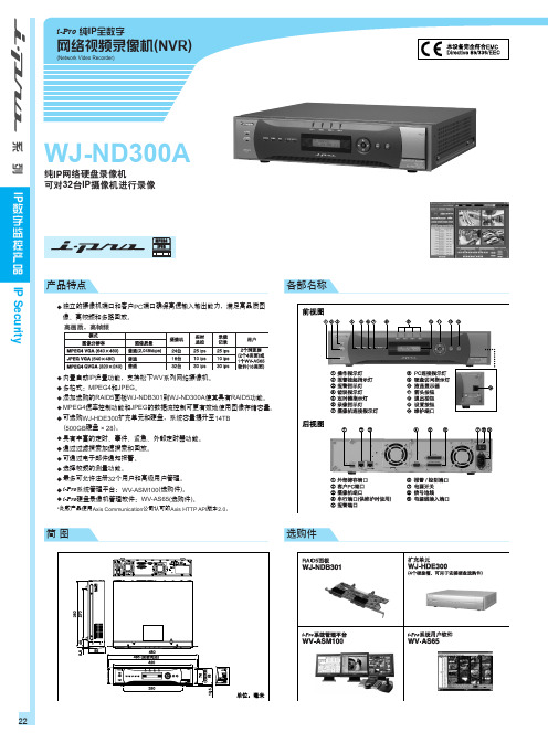
内置自动IP设置功能,支持松下WV系列网络摄像机。 多格式:MPEG4和JPEG。 添加选购的RAID5面板WJ-NDB301到WJ-ND300A使其具有RAID5功能。 MPEG4速率控制功能和JPEG的数据流控制可更有效地使用图像存储容量。 可选购WJ-HDE300扩充单元和硬盘,系统容量提升至14TB (500GB硬盘 × 28)。 具有丰富的定时、事件、紧急、外部定时器功能。 通过过滤搜索加速搜索和回放。 可通过电子邮件通知报警。 选择帧频的测量功能。 最多可允许注册32个用户和高级用户管理。 i-Pro系统管理平台:WV-ASM100(选购件)。 i-Pro硬盘录像机管理软件:WV-AS65(选购件)。 *此款产品使用Axis Communication公司认可的Axis HTTP API版本2.0。
系统图
IP Security
系 列 IP
数 字 监 控 产 品
23
简图
选购件
IP Security
22
规格
支持的摄像机 类型 录像机 浏览器GUI
报警 / 时间 网络
外部协议 硬盘驱动器 观看软件 管理软件 快速IP设置软件 一般规格
支持的摄像机型号 支持的图像格式 图像分辨率 最多摄像机数量 录像模式 预警录像 定时录像模式 帧频 / 摄像机 摄像机控制 录像 / 回放控制 搜索模式 显示模式 摄像机组 图像下载 SD记忆卡(存息 系统日志 时间同步 夏令时 GUI / 系统设置语言 系统支持 支持浏览器 报警源 事件模式 报警联动 报警控制 事件日志 网络协议 最大带宽 带宽控制(客户机端口) 支持网络协议 Email 同时操作的客户机数量 用户注册 用户级别 分区 安全方式 报警接口(25针 D-sub) 报警 / 控制接口 (25针D-sub)
4-300G蓝光盘库技术对比(松下与索尼对比)

蓝光盘库技术方向对比【概况】Panasonic采用模式:单光驱单光头(单面刻录1光头,双面2光头),由多个光驱构成光驱组的模式他社:但光驱内集成多组光头(单面4光头,双面8光头)的模式【比较】1,读/写速度比较P社模式下读/写速度一致,均为360MB/s(=30MB/s*2*6)他社模式下,由于散热会影响误码率,使用寿命等一系列问题,在数据刻写时集成在同一光驱内的8个光头无法同时工作,部分光头必须处于待机状态,导致刻写速度仅为140MB/s。
数据读取时功耗较低,8个光头同时工作,读取速度280MB/s。
目前MAM系统最多可支持6组光驱,在满配光驱情况下,双方的系他社模式通过占用盘匣空间提高系统速度,以牺牲盘柜容量密度换取系统速度的提升2,未来发展性比较随着光盘容量提升,单光头速度随之提升。
单光头速度为N[MB/s]时,两种模式下的刻写速度分别为P模式:N*12[MB/s]它社模式:N*4[MB/s]随着N的增长,量模式下的系统速度逐渐拉大。
他社模式存在扩容性,可发展性,系统速度的提升的一系列无法解决的问题。
P社模式不存在上述问题并,且可确保读写速度一致,并均有良好的扩展性。
3,可对应最大单个文件容量P社模式以盘匣为单位,可对应的最大单个文件大小为1.8TB。
他社模式以光盘为单位,可对应最大文件大小仅为300GB,超过300GB需对文件进行分割,影响读/写效率4,数据安全性P社模式多张光盘同时读/写,可采用与HDD类似的RAID5,6提高存储安全级别。
他社无法对应RAID模式,与LTO类似,只能采取多倍备份的模式,消耗空间过大5,读写效率P社模式读取同一盘匣内数据均无需更换盘片,效率高他社模式下需更换盘片,导致读取时间增加6,P社盘库中所采用的所有硬件部分(机械手臂,光驱,光盘)均为P社自主研发及生产的产品,在产品兼容性,持续性,将来性方面拥有决定权。
他社盘库中关键硬件部分为指定工厂进行代工的产品,在研发,生产,兼容性等方面存在风险。
松下 食物混合器 MK-CM300 使用说明书

容器内。 ● 请勿搅拌过长时间,按菜单操作即可。对于干的混合物,一般要用低档搅拌。 ● 气候条件、季节温度变化、混合成分温度及食材都随时在变化,这些都会对搅拌时间及
切碎放入。 搅拌容器所容纳的食材最大容量和最小容量:
配件
原料
最大容量 重量 操作时间 速度
最小容量 重量 操作时间 速度
搅面钩
高筋面粉+ 水
600克面粉 +300克水
5分钟
2
300克面粉 +190克水
11分钟
1~3
搅拌桨
肉馅
600克肉+ 450克卷心菜
4分钟
4
400克肉+ 300克卷心菜
4分钟
4
打蛋器 蛋清
6
20220804 MK-CM300 中国向 -.indd 6
2022/9/1 10:41:13
准备
安装与拆卸
安装
1 确保本产品插头已从电源插座拔出,且“开关旋钮”位于“ 0 ”。
2 按下“释放钮”,上部会自动释放,用手轻轻地向后抬起并锁定在抬头位置。 ● 取下搅拌容器清洗干净。 ● 把需要搅拌的食材放入搅拌容器内。
请务必遵守
为了避免危害使用者以及给他人造成财产损失,特此说明下列务必遵守的事项。 ■ 因错误操作产生的危害以及损失的程度,予以区分说明。
警告: 表示有可能导致重伤或死亡的潜在危险。 注意: 表示有可能导致轻伤或财产损失的潜在危险。
■ 针对务必需要遵守的事项,用以下符号予以区分说明。
表示必须禁止的事项。
LX3参数
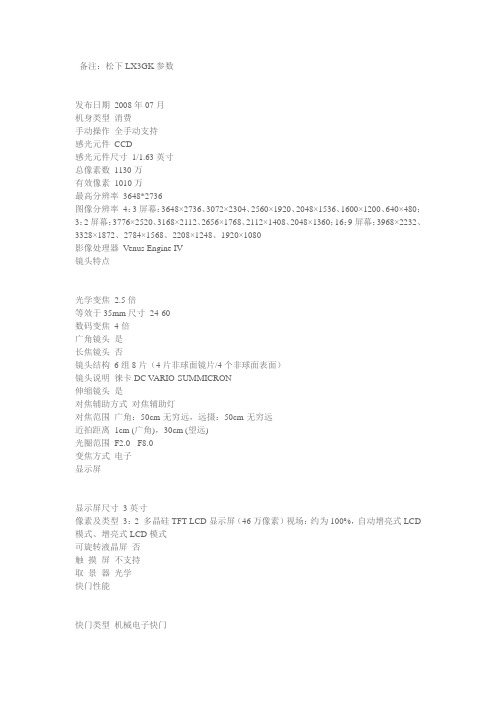
备注:松下LX3GK参数发布日期2008年07月机身类型消费手动操作全手动支持感光元件CCD感光元件尺寸1/1.63英寸总像素数1130万有效像素1010万最高分辨率3648*2736图像分辨率4:3屏幕:3648×2736、3072×2304、2560×1920、2048×1536、1600×1200、640×480;3:2屏幕:3776×2520、3168×2112、2656×1768、2112×1408、2048×1360;16:9屏幕:3968×2232、3328×1872、2784×1568、2208×1248、1920×1080影像处理器Venus Engine IV镜头特点光学变焦2.5倍等效于35mm尺寸24-60数码变焦4倍广角镜头是长焦镜头否镜头结构6组8片(4片非球面镜片/4个非球面表面)镜头说明徕卡DC V ARIO-SUMMICRON伸缩镜头是对焦辅助方式对焦辅助灯对焦范围广角:50cm-无穷远,远摄:50cm-无穷远近拍距离1cm (广角),30cm (望远)光圈范围F2.0 - F8.0变焦方式电子显示屏显示屏尺寸3英寸像素及类型3:2 多晶硅TFT LCD显示屏(46万像素)视场:约为100%,自动增亮式LCD 模式、增亮式LCD模式可旋转液晶屏否触摸屏不支持取景器光学快门性能快门类型机械电子快门快门速度自动:1-1/2000秒,光圈/快门优先:8-1/2000秒,手动:60-1/2000秒,夜景模式15,30,60秒闪光灯闪光类型外接支持热靴是闪光模式自动、自动/降低红眼、慢速同步/降低红眼、强制开启/关闭闪光范围0.8-8.3 m(广角/ ISO自动),0.8-5.9 m(长焦/ ISO自动);高感光度模式:1.15 - 21.2m (广角),0.9 - 15.1m (长焦)曝光控制曝光模式程序自动曝光,光圈优先,快门优先,手动曝光曝光补偿±2.0 EV 每级1/3EV可调测光方式智能多点测光,中央重点测光,点测光白平衡自动,白天,阴天,阴影,色温,卤素灯,闪光灯,白色设置1,白色设置2;±9级调节(自动除外)感光度自动ISO 80、100、200、400、800、1600、3200(高感光度模式:自动(1600-6400))高感光度是拍摄性能防抖性能光学防抖场景模式肖像、柔化肌肤、风景、运动、夜景肖像、夜景、自拍、食物、派对、烛光、焰火、星空、沙滩、航拍、雪景、高感光度、宝宝1&2自拍功能支持10秒或2秒延时连拍功能全分辨率照片,2.5帧/秒最多拍摄8张(标准模式),最多拍摄4张(精细模式),最多拍摄3张(RAW);高速连续拍摄模式:约6帧/秒(拍摄4:3画面:3M,3:2画面:2.5M,16:9画面:2M)短片拍摄4:3宽高比:640 x 480像素:30帧每秒、320 x 240像素:30帧每秒、10帧每秒;16:9宽高比:848 x 480像素:30帧每秒,HD:1280 x 720:24帧每秒MPEG-4视频录制不支持录音/音频系统支持高清摄像支持操作功能菜单语言英文、德文、法文、西班牙文、意大利文、简体中文、繁体中文、俄文、日文存储性能存储卡类型SD/SDHC/MMC卡记录容量50 MB文件格式静像:JPEG(相机文件系统设计规范,基于Exif2.2标准),符合DPOF,RAW,RAW+JPEG;影像:QuickTimeMotionJPEG接口性能数据接口USB2.0视频接口DC输入/AV输出电池性能电池类型专用锂电池.7V, 1150mAh外接电源交流电转接器(输入:交流110-240伏)(供选)续航能力约拍摄380张(CIPA标准)外观设计外形设计银色、黑色轻巧机身否时尚超薄否大屏幕LCD 是其他性能外形尺寸108.7 x 59.5 x 27.1 mm产品重量229克(机身),265克(包括电池和SD记忆卡)随机附件电池充电器、电池组、电池便携盒、A V接线、USB接线、AC接线、相机带、CD-ROM光盘随机软件PHOTOfunSTUDIO -viewer- 2.1 E,SILKYPIX Developer Studio 3.0 SE,ArcSoft MediaImpression, ArcSoft Panorama Maker, QuickTime,USB Driver仅供参考,请以当地实际销售产品信息为准备注:松下LX2 外观设计外形设计黑色、银色外形尺寸105.7 x 55.8 x 26.3 mm产品重量约187克轻巧机身是时尚超薄否大屏幕LCD 是松下LX2 基本性能手动操作全手动支持机身类型消费数码相机感光元件CCD传感器尺寸1/1.65英寸总像素数1040万有效像素1020万最高分辨率3168*2376图像分辨率4:3 Aspect Ratio3168 x 23762880 x 21602304 x 17282048 x 15361600 x 12001280 x 960640 x 4803:2 Aspect Ratio3568 x 23763248 x 21602560 x 17122048 x 136016:9 Aspect Ratio4224 x 23763840 x 21603072 x 17281920 x 10像素松下LX2 显示屏显示屏尺寸 2.8英寸像素及类型2.8英寸多晶硅TFTLCD显示屏(207,000像素)可旋转液晶屏否取景器无松下LX2 电池性能电池类型专用锂电池外接电源Optional AC adapter续航能力约拍摄300张松下LX2 存储性能记录媒介MMC(多媒体卡)/SD(如意卡)记录容量13 MB图像格式图片: JPEG (Exif 2.2)动画: QuickTime Motion JPEGRAW松下LX2 镜头特点光学变焦4倍数码变焦4倍广角镜头是长焦(光变=>8)否等效于35mm尺寸焦距等效于传统35mm相机的28-112mm镜头结构f=6.3-25.2 mm,徕卡DCV ARIO-ELMARIT,8组9片(3片非球面镜片)镜头说明徕卡镜头对焦范围广角50cm/ 长焦100cm - 无穷远近拍距离广角5cm/ 长焦30cm - 无穷远光圈大小F2.8 - F8.0 (广角) F4.9 - F8.0 (长焦)感光度80/100/200/400/800/1600/3200变焦方式电子伸缩镜头是对焦辅助方式对焦辅助灯对焦方式自动聚焦系统、标准/微距、连续自动聚焦开/关(仅限静像)、手动聚焦松下LX2 闪光灯闪光类型内置支持热靴否闪光模式自动、自动/降低红眼、慢速同步/降低红眼、强制开启/关闭闪光范围0.6 - 4.9m (广角/ISO Auto), 0.3 - 2.2m (长焦/ISO Auto)松下LX2 拍摄性能自拍功能支持2秒或10秒连拍功能2帧/秒或1帧/秒,标准质量最多连拍5张,高质量最多连拍3张动态拍摄4:3屏幕:640x480,320x240:30fps,10fps。
- 1、下载文档前请自行甄别文档内容的完整性,平台不提供额外的编辑、内容补充、找答案等附加服务。
- 2、"仅部分预览"的文档,不可在线预览部分如存在完整性等问题,可反馈申请退款(可完整预览的文档不适用该条件!)。
- 3、如文档侵犯您的权益,请联系客服反馈,我们会尽快为您处理(人工客服工作时间:9:00-18:30)。
松下蓝光盘库技术指标清单
※为必选项
※1、智能化蓝光盘库,冗余设计,采用国际知名品牌,具有完全知识产权的产品,原厂生产,非OEM或贴牌产品(需提供生产厂家证明);
※2、专用归档级蓝光光盘:光盘匣裸盘状态下容量3.6TB/匣(单张光盘容量300G/张,12张光盘/匣),有防潮、防尘、耐高温特性。
保存周期50年;
※3、本次配置至少支持532个槽位,配置盘匣532个,容量1915TB,搭载12台驱动器,隔代兼容性好,50年免迁移,可扩展;
※4、光盘驱动器:单机柜配置6台驱动器(1组),单组驱动器读/写文件时速度可达到360MB/s(RAID 0),RAID6状态下读/写速度达到300MB/s以上;
※5、冗余功能,安全级别高:具备盘匣内冗余功能(支持RAID技术),根据使用设置可保证盘匣内1张光盘(或两面)损坏的条件下恢复光盘匣内所有数据的功能;
6、同一盘匣内可存储最大单个文件容量为1.8TB, 无需文件切割、切换光盘等处理;
7、具有故障自诊断功能;支持光盘匣检测功能,对驱动器、机械手臂的工作情况进行记录、及时预警,保证数据安全;
※8、承诺与平台厂家合作进行软件研发并免费升级,实现平台管理软件对盘库的直接控制管理,无需盘库自带的管理软件或第三方软件,以提高可靠性、安全性与效率(需提供双方确认盖章的承诺书);
※9、平台管理软件支持蓝光库通过无缓存方式进行读写的功能;
10、平台管理软件支持LTO磁带到蓝光盘的转存(数据迁移);
11、平台管理软件支持打点下载功能;
12、平台管理软件支持已归档到光盘匣中的实例的删除和导出;
13、平台管理软件支持对用户指定的光盘匣进行健康检查的功能,并对盘匣内数据的可读性(安全性)进行检测;
14、为保证离线管理的需求,可对盘匣进行离线管理,提供1/2维码离线管理模式;
15、光盘库视频格式需求:支持MXF、Matrox_Avi、Riff-Avi、ODML_AVI、WAV、MP3、MP4、H.264等主流视频格式;
16、接口:蓝光盘库对外接口可在FC/iSCSI/SAS中进行选择;
17、19英寸机柜:可放入19英寸尺寸(机柜深度1100mm,宽度600mm,满配机柜高度为50U);
※18、核心部件如光驱包括光驱激光头、档案级光盘等,系自主研发并生产,兼容性好(需提供生产厂家证明),易维护:模块化设计,备品易更换;
19、保存环境要求低:温度:10℃-40℃;湿度:10%-90%RH;
※20、投标厂家必须提供生产厂家针对本项目的授权及原厂服务承诺函;
※21、获得国内广电行业产品技术大奖。