DPC使用手册资料
富士施乐DPC2255产品培训维修
3. 更换重要信息存储元件时的注意事项: 机器安装之后,客户输入的有些数据非常重 要,任何人不得丢失或泄漏数据。工程师必须识别储存此类数据的零件, 小心更换.详 细步骤请参考维修手册第四章4.3.3节
工程师诊断工具1: 诊断模式(Diag. Mode)
通过IC Card*2身份认证实现机密打印 9在硬盘上保存带有密码保护的文件 9无需打印服务器 9两种授权认证方式:
z在打印机面板上 z输入密码IC Card
*1 需硬盘选件. *2 需 IC Card Gate 2 (for FeliCa)选件.
无需打印服务器!
EP-A 保护
在面板上 输入密码
客户机
1. CE工具目的: 与用户可以使用的通用菜单相同,添加CE专用项目的工具。添 加项目为“报告/列表”通用菜单的以下模式菜单。
• HFSI计数器报告 • 卡纸历史报告 • 关机历史报告 • 故障历史报告 • Debug(调试)日志报告
2. 进入CE工具的方法 ① 在液晶画面显示“可以打印”的状态下,按<▼>键3次,然后按<菜单>键。 可打印指示灯(绿)熄灯,同时液晶画面上显示诊断通用菜单的初期画面 “菜单-打印机语言设定”。 ② 进入CE工具后,按<▲>/<▼>键从通用菜单选择相应的菜单画面。
DC132 Set Serial (仅在发生特定故障时才显
示)
1)Diagnostics Preventive Diag (预防保全)
DC301 NVM Initialize
确认异常发生次数、消耗品消耗情况,预防机器故障。 4) Diagnostics Subsystem Check (子系统确认)
Intel oneAPI DPC++ Library 用户指南说明书

Get Started with the Intel® oneAPI DPC ++ LibraryGet Started with the Intel® oneAPI DPC++ LibraryContentsChapter 1: Get Started with the Intel® oneAPI DPC++ Library 2Get Started with the Intel® oneAPI DPC++ Library 1Intel® oneAPI DPC++ Library (oneDPL) works with the Intel® oneAPI DPC++/C++ Compiler to provide high-productivity APIs to developers, which can minimize SYCL* programming efforts across devices for high performance parallel applications.oneDPL consists of the following components:•Parallel API•API for SYCL Kernels•MacrosFor general information about oneDPL, visit the oneDPL GitHub* repository, or visit the Intel® oneAPI DPC++ Library Guide and the Intel® oneAPI DPC++ Library main page.Quick StartInstallationVisit the oneDPL Release Notes page for:•Where to Find the Release•Overview•New Features•Fixed Issues•Known Issues and LimitationsInstall the Intel® oneAPI Base Toolkit (Base Kit) to use oneDPL.To use Parallel API, include the corresponding header files in your source code.All oneDPL header files are in the oneapi/dpl directory. Use #include <oneapi/dpl/…> to include them. oneDPL uses the namespace oneapi::dpl for most its classes and functions.To use tested C++ standard APIs, you need to include the corresponding C++ standard header files and use the std namespace.pkg-config SupportThe pkg-config program is used to retrieve information about your installed libraries, and to compile and link against one or more libraries.Use pkg-config with oneDPLUse pkg-config with the --cflags flag to get the include path to the oneDPL directory:dpcpp test.cpp $(pkg-config --cflags dpl)The --msvc-syntax flag is required when you use a Microsoft Visual C++* compiler. This flag converts your compiling and linking flags to the appropriate form:dpcpp test.cpp $(pkg-config --msvc-syntax --cflags dpl)NOTE Use the pkg-config tool to get rid of large hard-coded paths and make compilation moreportable.Usage Examples31 Get Started with the Intel® oneAPI DPC++ LibraryoneDPL sample code is available from the oneAPI GitHub samples repository. Each sample includes a readme with build instructions.<oneapi/dpl/random> Header Usage ExampleThis example illustrates oneDPL random number generator usage. The sample below shows you how to create an random number generator engine object (the source of pseudo-randomness), a distribution object (specifying the desired probability distribution), and how to generate the random numbers themselves. Random number generation is performed in a vectorized manner to improve the speed of your computations. This example performs its computations on your default SYCL device. You can set the SYCL_DEVICE_TYPE environment variable to CPU or GPU.template<int VecSize>void random_fill(float* usmptr, std::size_t n) {auto zero = oneapi::dpl::counting_iterator<std::size_t>(0);std::for_each(oneapi::dpl::execution::dpcpp_default,zero, zero + n/VecSize,[usmptr](std::size_t i) {auto offset = i * VecSize;oneapi::dpl::minstd_rand_vec<VecSize> engine(seed, offset);oneapi::dpl::uniform_real_distribution<sycl::vec<float, VecSize>> distr;auto res = distr(engine);res.store(i, sycl::global_ptr<float>(usmptr));});}Pi Benchmark Usage ExampleThis example uses a Monte Carlo method to estimate the value of π. The basic idea is to generate random points within a square, and to check what fraction of these random points lie in a quarter-circle inscribed within that square. The expected value is the ratio of the areas of the quarter-circle and the square (π/4). You can take the observed fraction of points in the quarter-circle as an estimate of π/4.This example shows you how to create an random number generator engine object (the source of pseudo-randomness), a distribution object (specifying the desired probability distribution), generate the random numbers themselves, and then perform a reduction to count quantity of points that fit into the square S. Random number generation is performed in scalar manner to simplify your code.4Get Started with the Intel® oneAPI DPC++ Library 1float estimated_pi;{sycl::queue q(sycl::gpu_selector{});auto policy = oneapi::dpl::execution::make_device_policy(q);float sum = std::transform_reduce( policy,oneapi::dpl::counting_iterator<int>(0),oneapi::dpl::counting_iterator<int>(N),0.0f,std::plus<float>{},[=](int n){float local_sum = 0.0f;oneapi::dpl::minstd_rand engine(SEED, n * ITER * 2);oneapi::dpl::uniform_real_distribution<float> distr;for(int i = 0; i < ITER; ++i) {float x = distr(engine);float y = distr(engine);if (x * x + y * y <= 1.0)local_sum += 1.0;}return local_sum / (float)ITER;});estimated_pi = 4.0f * (float)sum / N;}Find More51 Get Started with the Intel® oneAPI DPC++ Library6。
Hoffman DPC Series 电源分布单元与出口控制和监控系统用户手册说明书
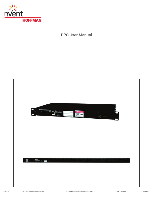
DPC User ManualDescriptionThe DPC Series consist of Power Distribution Units and Outlet Control and Monitoring with a built in web server in a self−contained unit. Web pages, including graphs, are generated from the unit, and monitor power and environmental conditions within the cabinet. No software other than a web browser is required, and several data formats are available. Built in sensors include Voltage, Current, and calculated Power Factor. Optional external sensors and network cameras are available and can be added. Specifications (See Unit Label for Ratings)Networking: HTTP, HTTPS (SSL/TLS), SMTP, POP3, ICMP, DHCP, TCP/IP, NTP, FTP.Data Formats: HTML, SNMP, CSV/Plain Text, Telnet, WAP, PDA formatted HTML, XML.EMC Verification: Class A digital device. This device complies with part 15 of the FCC Rules. Operation is subject to the following two conditions: (1) This device may not cause harmful interference, and (2) this device must accept any interference received, including interference that may cause undesired operation.Warning! Changes or modifications to this unit not expressly approved by the party responsible for compliance could void the user’s authority to operate this equipment. FCC requirements: The ferrite core shipped with the unit must be placed around the Ethernet cable close to the PDU.Receptacle Ratings: NEMA 5−15R 125 Volts, 15 AmpsNEMA 5−20R 125 Volts, 20 AmpsNEMA 6−20R 250 Volts, 20 AmpsModel OptionsInstallation1. Using appropriate hardware, mount PDU in rack or cabinet.2. Plug PDU into an appropriately rated and protected branch circuit receptacle.3. Connect PDU to network using Ethernet connection.4. Connect any External Sensors (Optional) to the unit.5. Plug in devices to be powered by PDU.6. Power on devices to be powered by PDU. Sequential power up is recommended to avoid high inrush current. Service and MaintenanceNo service or maintenance is required. Do not attempt to open the PDU, warranty will be void. No userserviceable parts insideSetting an IP AddressThe DPC units have a permanent IP address for initial setup and access to the unit if you forget the address you assign to it.The Configuration page allows you to assign the network properties or use DHCP to connect to your network. Access to the unit requires the IP address to be known, so use of a Static IP or reserved DHCP is recommended. The permanent address is shown on the front of the unit.192.168.123.123I PAddress:Net Mask: 255.255.255.0Gateway: 192.168.123.1First Time Setup:1. Connect the DPC to your computer using a crossover cable or a hub.2. On your computer, go to ”Start > Settings > Control Panel > Network and Dial Up Connections”3. Right Click on ”Local Area Connection” and select ”Properties”4. Select the option to “Use the following IP address” and enter:192.168.123.1I Paddress:Subnet mask: 255.255.255.0Default gateway: Not Needed5. Click ”OK” twice6. You can now access the unit using your web browser at the permanent IP address, http://192.168.123.123CardSettingsNetworkT ypicalfor PC or Laptop to connect tobackup IP address. Note thata Default Gateway is not needednor recommended.Remote Outlet Switching/Monitoring ConfigurationThe DPC is equipped with individually switchable outlets. Total current for each group of outlets is available on the Sensors page and on the Control page.The unit will list all available outlets under “DPC Configuration” on the Control page. Each outlet has five fields associated with it:1. Name: A friendly name to easily identify what is plugged into the outlet, for example “Mail Server.”2. URL: Enter a URL associated with the equipment plugged into the outlet. This URL will appear as a clickablelink at the top of the Control Page next to the outlet status information.3. Power−On Delay: Delay from the time the “On – Delayed” action is executed until the outlet will turn on.4. Power−Off Delay: Delay from the time the “Off – Delayed” action is executed until the outlet will turn off.5. Reboot Delay: Delay from the time the “Reboot” action is executed and all selected outlets have turned offuntil the outlet will turn back on.The Max Group Amps (MGA) setting is a protective feature designed to help eliminate downtime due to overloading of a power strip. The unit will not allow any more outlets in the same group to turn on once the MGA threshold has been reached. For example, if MGA is set at 10A, there are 3 outlets enabled in Group A and the total draw for Group A is 9A, the unit will allow a fourth outlet to turn on. However, if after enabling the fourth outlet, the current draw were to rise to 11A, no more outlets in Group A would be allowed to turn on. If the total draw drops below 10A, another outlet will be allowed to turn on.NOTE: DPC will not shut off any outlet automatically, even if the MGA has been exceeded. It is still possible to overload the strip if the load on any outlet is increased after the outlet is turned on. It is advisable to set an alarm on each group based on the MGA as an additional warning of potential problems.Remote Outlet Switching ControlThere are six possible actions for any given outlet, available from the “Action” drop down box on the Control page:1. On – Immediate: Turns on all checked outlets immediately.2. On – Delayed: Turns on all checked outlets subject to the “Power On” delays entered at the bottom of theControl page.3. Off – Immediate: Turns off all checked outlets immediately.4. Off – Delayed: Turns off all checked outlets subject to the “Power Off” delays entered at the bottom of theControl page.5. Reboot: Turns off all checked outlets immediately and turns them back on subject to the “Reboot” delaysentered at the bottom of the Control page.6. Cancel Actions: Cancels any actions currently in progress on the selected outlets.To perform an action, select the check box next to the outlets needing attention, select an action from the drop down box and click the “Execute” button. A dialog box will appear asking for confirmation of the selected actions. Click OK to allow the action to proceed or click Cancel to make changes.Internal SensorsAll internal sensors are measured every 5 seconds. External sensors are measured every 10 to 30 seconds depending on the #of devices connected. Sensor data collected by the Hoffman Smart unit gives useful trend analysis data. While all values are not absolute in relation to a known unit, trend analysis of the data allows users to view changes in data value over time. Analysis of the change in value of the data can lead the user to useful conclusions about what is happening in the monitored environment. Volts – Measures instantaneous RMS voltage.Volts (Peak) – Reports the highest reported voltage since the last time the data was updated, typically every 5 seconds.Amps – Measures instantaneous RMS current.Amps (Peak) – Reports the highest reported current since the last time the data on the screen was updated, typically every 5 seconds. Real Power – Average of instantaneous voltage and current over the last 1.5 seconds.Apparent Power – The product of instantaneous RMS Voltage and RMS Current. This is the value used by circuit breakers. Power Factor – The ratio of Real Power to Apparent Power.Amps Group – Reports the group SUM of individual receptacle readings.Connecting Optional RJ Remote SensorsPlug and Play Remote Sensors may be attached to the unit and in some cases splitters may be required to add additional sensors. Each sensor has a unique address and is automatically discovered and added to the webpage. Note: the display order of the sensors on the web page is determined by the internal ID of each sensor, a customizable friendly name is available for each on the Display page.The supplied wires can be extended or shortened using Cat 3 wire and RJ12 connectors. Note: the sensor wire has six conductors, wiring must be straight−through: reverse polarity will temporarily disable all sensors until corrected. The sensors use a serial communication and are subject to network signaling constraints dependent on shielding, environmental noise, and length of wire. Typical installations should allow runs of up to 600 feet of sensor wire.Optional RJ Remote SensorsDST TemperatureDSTA Temperature / AirflowDSTAH Temperature / Airflow / Humidity******************************************************************************Graphing and Displaying DataAll data collected by the unit can be graphed. The Log page allows the user to select graphed content and sampling rate, selected items will be displayed on LCD (on units where it is present, or optional Remote Display). The amount of data and sample rate determine the graph time span. This period is calculated and displayed on the Log page. When the onboard memory fills up,old data will be deleted, making room for new data. All settings are stored in case of a power loss or reboot. A sample rate of30 seconds or longer is recommended to allow the unit to gather all sensor data before graphing. Sampling rates of 60 to 120 seconds should provide ample resolution for most situations.Setting AlarmsFor all data collected by the unit, the user can set high and low limits. When these limits are exceeded the user has the option of sending an email, SNMP trap, activate the audible alarm (on units where it is present), or any combination of the three. The SNMP traps can be sent to 4 IP addresses. Some analysis of each unit is recommended before setting alarm limits. Once each unit has been operating in the environment under normal, steady state conditions for several hours, alarm set points may be chosen. By allowing the unit to come to steady state before setting alarm set−points, the user may make more informed decisions about the normal variation in conditions and choose alarm set points that will inform when conditions are truly changing without triggering numerous false alarms. Aside from using historical graphs to make alarm set−point decisions, the user may choose to download raw log data from the logs page to see specific historical data records and use this data to help set useful alarm set−points. Note: Changes in settings are processed less frequently and depending on the number of attached devices may take several minutes to respond. Rapidly resetting alarm values may not provide desired results. Allow up to 2 minutes after making a setting change before modifying. Test alarms can be sent for each measured value via the Alarms page.Optional DRD Remote DisplayThis small module can be mounted in an accessible spot inside or outside the rack or cabinet. A LCD display scrolls values of items selected on the Logs page. The connection to the unit is made with a 10’ handset type 4−conductor cable. The buzzer can be activated for alarm states to identify problems. An alarm reset is located next to the display to silence the buzzer when the problem is located. The LED indicator stays on in alarm state even after the buzzer has been silenced.Optional IP−Enabled Web CameraThe unit has been designed to allow up to 4 IP Network Cameras to interface with the webpage. To enable this feature the camera must be set to allow anonymous access. The unit Configuration page allows you to add the IP address of the camera and specify the model. This live image will appear on the Sensors page and will update with the webpage. Clicking on the picture itself will take you to the IP address of the camera. Each device currently supports up to 4 cameras simultaneously.Supported Cameras: Axis 205/206, D−Link DCS−900, D−Link DCS−950/G, D−Link DCS−5300/GOther Formats• PDA Displays data in a small screen format for a PDA.• WAP Wireless Application Protocol, displays text values for wireless clients such as mobile phones and some PDAs.• XML Extensible Markup Language, displays values in XML format.• MIB Management Information Base, downloads the MIB to be used for SNMP applications.Accounts, Passwords and SecurityThe unit is accessible via a standard, unencrypted HTTP connection as well as an encrypted HTTPS (SSL) connection. The user may opt to enable access via HTTP, HTTPS, or both HTTP and HTTPS. It is not possible to disable the web interface completely. The unit has a View−Only account, a Control Access account, and an Administrator account. When activated the Administrator account limits access to any web pages with configuration settings. When left blank no username or password is required to adjust the configuration. When activated, the View−Only account requires a username and password to view sensor data. The Control Access account allows access to the Control page, allowing configuration of attached switch−able power distribution units. The Administrator account must be password protected to activate the View−Only and Control Access accounts. The user may choose any name for the Administrator, Control Access, and View−Only accounts consisting of alphanumeric characters, spaces, and underscores, except for “root” and “admin”. These account names are disabled for security reasons and cannot be re−enabled.WARNING! Record your password. Loss of password will require the unit serial number and contact of customer serviceto be recovered.Setting Time and DateThe unit comes preconfigured with the IP addresses of two military NTP servers and set to the Central Time Zone (−500 GMT). Should a local time server be preferred, enter its IP address into the box and click the “Save Changes” button. Should the user need to revert back to the military time servers, simply clearing the time server addresses and clicking “Save Changes” will set the time servers back to the defaults. The unit attempts to contact the timeservers while booting up. If a timeserver is unavailable, all log time stamps will present time as the number of seconds since the unit was powered up. Note: that the time and date are not adjusted for daylight savings time. Setting the time zone offset forward and backward an hour will cause a gap or overwriting of logs, respectively.TelnetWhen using Telnet to connect to the unit, the Administrator username and password from the Configuration page will be required. If the Administrator user is not configured, the Telnet server will be enabled, but logins will be impossible. The Telnet server can be disabled on the Configuration page. Available Telnet commands can be found by using the command “help”. The following are some commonly used Telnet commands:Airflowset – Resets the internal airflow sensor such that the current flow is measured as ‘20’.Exit – Terminates the Telnet connection.Reboot – Reboots the controller board remotely. Power distribution is not affected.Report – Displays a report of all connected sensors and their current values.Time – Displays the current date and time according to the unit if the unit has contacted an NTP server.System info – Displays general information about the unit, including: Unit type, Software version and MAC address.SNMPThe unit is accessible via SNMP and can be configured to send out SNMP traps to a maximum of 4 IP addresses when alarm conditions are met. The community string defaults to “public,” but is user−customizable on the Configuration page. The MIBis downloadable via a link at the top of the web interface. The MIB is walk−able via any SNMP browser, but will have to be imported before doing so. The SNMP service can be disabled via the Configuration page. A test SNMP trap can be sent from the Configuration page.E−MailThe unit is capable of sending e−mail to a maximum of 5 e−mail addresses when alarm conditions are met. E−mail settings are on the Configuration page. An SMTP server, a “From” address and a “To” address are required to send email alerts. Some e−mail servers are password protected and will require a POP server, username and password for validation. In most cases, the username does not have to match the “From” address, but does need to be a valid user on the POP server. Microsoft Exchange servers will have to be set to allow SMTP relay from the IP address of the unit. A local network administrator will have to change this setting.A test email can be sent from the Configuration page.Daily AffirmationDaily Affirmation allows the users to choose a frequency with which the unit will forward a full status report to their e−mail. This status report can come hourly, every 2, 4, 8, or 12 hours, or once daily (24 hours). This feature allows you to know that everything is still running, and gives you an update on all attached devices as well. Set−up of this feature is on the Configuration page under ”Status Reports”.Owner Contact InformationOwner contact information can be entered on the Configuration page and will display at the bottom of the web interface. Firmware Upgrades and Additional InformationNew firmware upgrades and additional information is available at /pdu。
Profibus-DP使用手册c

'5,9(6352),%86 '3 6/$9(&20081,&$7,216,17(5)$&()RU 63URGXFW 0DQXDO© &RS\ULJKW (XURWKHUP 'ULYHV /LPLWHGAll rights strictly reserved. No part of this document may be stored in a retrieval system, or transmittedin any form or by means to persons not employed by a Eurotherm group company without written permision from Eurotherm Drives Lt d.Although every effort has been taken to ensure the accuracy of this document it may be necessary,without notice, to make amendments or correct omissions. Eurotherm Drives cannot accept responsibilityfor damage, injury, or expenses resulting therefrom.&RQWHQWV&KDSWHU 3URGXFW &RGH&KDSWHU 3URGXFW )HDWXUHV &KDSWHU ,QVWDOODWLRQ&KDSWHU &RQQHFWLRQ 7(50,1$/6%86 7(50,1$7,21 5(3($7(5 &KDSWHU 'ULYH 6HW 8S 35272&2/ 237,21 $''5(66 237,21 9(56,21 &KDSWHU &RQILJXUDWLRQ ,'(17,),&$7,21 180%(5 ,'(17B180%(5 &21),*85$7,21 '$7$ &)*B'$7$ 86(5 3$5$0(7(5 '$7$ 865B350B'$7$ &KDSWHU 'HPDQG 'DWD 3URWRFRO &KDSWHU 3HUIRUPDQFH &KDSWHU 7URXEOHVKRRWLQJ 67$786 /('6 (;7(51$/ &20081,&$7,216 )$8/7 &21),*85$7,21 )$8/7 ,17(51$/ &20081,&$7,216 )$8/7 $33(1',; $ 'HYLFH 'DWD %DVH ''% )LOH$ $33(1',; % 6LHPHQV &20 (7 &RQILJXUDWLRQ )LOH% $33(1',; & 'HFLPDO WR +H[DGHFLPDO &RQYHUVLRQ&&KDSWHU 3URGXFW &RGH&KDSWHU 3URGXFW &RGHThe Profibus Option may either be purchased with a drive, or separately.With 584S:584S/xxxx/xxx/xxxx/xx/xxx/PR00/xxx/xx/xxx/xxxWith 590:590/xxxx/x/x/x/x/x/2/xxxx/xxx/xxx/xxx/x/xx/xx/xx/xx/xxxWithout Drive:AH389918U001&KDSWHU 3URGXFW )HDWXUHV &KDSWHU 3URGXFW )HDWXUHVPROFIBUS-DP (DIN 19245 - 3) compliance tested.Connection using shielded twisted -pair.Auto-Baud search 9.6/19.2/93.75/187.5/500/1500kBaud.Maximum of 12 Process Data parameters, selected from any of the Drives’ parameters.Process Data parameters selected by PROFIBUS-DP-Master.Demand Data protocol to provide random access to any parameter within the Drive.LEDs to indicate board and communications status.Suitable for use with:584S software V5.1 onwards590software V4.2 onwards&KDSWHU ,QVWDOODWLRQ&KDSWHU ,QVWDOODWLRQThe PROFIBUS-DP-SLAVE Option Board is fitted on the site at the bottom right-hand corner of the Drive Control Board. Note that this option board is fitted instead of the Serial Link Option Board.WARNING - DO NOT INSTALL OR REMOVE THE OPTION BOARD WITHTHE DRIVE POWERED.&KDSWHU &RQQHFWLRQ&KDSWHU &RQQHFWLRQThe 6-pin Phoenix connector is used to connect to the Profibus network.PROFIBUS-DP_SLAVE OPTION BOARD1 623 457(50,1$/63LQ 5HIHUHQFH0HDQLQJ*1'H[W 3URWHFWLYH JURXQG IRU 3URILEXV 9'&H[W 9'&H[W P$ VXSSO\ IRU 3URILEXV % %·5HFHLYH 7UDQVPLW 'DWD 3 $ $·5HFHLYH 7UDQVPLW 'DWD 1 576)RU FRQQHFWLQJ UHSHDWHU*1'H[W$V SLQ%867(50,1$7,21The GNDext (1) and +5VDCext (2) terminals are provided to allow the connection of terminatingresistors.390 Ω390 Ω220 ΩGNDext (1)+5VDCext (2)B-B’ (3)A-A’ (4)All resistors \ 5%, min. 1/4 W5(3($7(5Terminal 5 provides a TTL level signal that can be connected to a repeater. Most repeaters automatically switch between transmitting and receiving, so do not need this connection.&KDSWHU 'ULYH 6HW 8S&KDSWHU 'ULYH 6HW 8SThere are three parameters associated with the Profibus Option. These are:PROTOCOLOPTION ADDRESSOPTION VERSIONAll parameters are in the SERIAL LINKS::MAIN PORT (P1) menu of the MMI.35272&2/The PROTOCOL parameter must be set to OPTION.Note - when set to OPTION, the BAUD RATE parameter is ignored.237,21$''5(66The OPTION ADDRESS parameter is used to specify the PROFIBUS-DP-SLAVE address for the Drive.Valid PROFIBUS addresses are in the range 0 to 125.If the OPTION ADDRESS parameter is changed, the Drive must be powered off then on before the Drive will respond to the new address.237,219(56,21The OPTION VERSION parameter is a diagnostic which shows the version number of the PROFIBUS board. If no board is fitted, 0.00 is displayed.&KDSWHU &RQILJXUDWLRQ&KDSWHU &RQILJXUDWLRQAll configuration, other than setting the PROTOCOL and OPTION ADDRESS within the Drive, is done via the Profibus-DP-Master. During the start-up phase, the Profibus-DP-Master will check that the Profibus-DP-Slave at the requested address is of the required type. If it is, Configuration Data and User Parameter Data are downloaded.,'(17,),&$7,21180%(5 ,'(17B180%(5The registered Identification Number for this option board is:0x0533 (1331 decimal)&21),*85$7,21'$7$ &)*B'$7$The Configuration Data (Cfg_Data) is used to specify the number of parameters that are to be read and written as part of the cyclic Data Exchange.The Data Exchange either consists of just Process Data or Demand Data and Process Data. Process Data is the fixed set of parameters that are to be transferred each cycle. Demand Data is 8 reserved bytes (octets) to support a messaging system, allowing random access to any parameter within the drive. This is described in the following chapter.73811ORProcess Data (2 Parameters)Demand DataTo enable the Demand Data feature, the first byte of Cfg_Data is set to 0x73 (115 decimal). The number of Inputs and Outputs in the Process Data is defined by setting bytes to either 0x50 (80decimal) or 0x60 (96 decimal).,QGH[1R 'HPDQG 'DWD,QGH[:LWK 'HPDQG 'DWD,GHQWLILHU %\WH +H[DGHFLPDO$FWLRQ[ (QDEOH 'HPDQG 'DWD[ 5HDG VW 3DUDPHWHU [ :ULWH VW 3DUDPHWHU [ 5HDG QG 3DUDPHWHU [:ULWH QG 3DUDPHWHUHWF HWF HWF HWF[5HDG WK 3DUDPHWHU[ :ULWH WK 3DUDPHWHUFor example:,QGH['DWD0HDQLQJ[ VW 3DUDPHWHU ,QSXW 1R 'HPDQG 'DWD[ QG 3DUDPHWHU ,QSXW[ UG 3DUDPHWHU 2XWSXW[ WK 3DUDPHWHU 2XWSXWThe supported Identifier Byte formats are defined by the Profibus Standard to have the following meaning:,GHQWLILHU,QSXW 2XWSXW/HQJWK)RUPDW&RQVLVWHQF\[ ,QSXW :RUG1RQH[ 2XWSXW :RUG1RQH[ ,Q DQG 2XW :RUG1RQHNote - all parameter values are transferred as Words (2 octets).86(53$5$0(7(5'$7$ 865B350B'$7$The User_Prm_Data is used to specify the Tag numbers of the parameters that are to be read or written as Process Data. Each parameter is represented by 2 bytes in the User_Prm_Data, these specify the Tag number in High-Byte/Low-Byte order.The User_Prm_Data must always be 24 Bytes long. If less than 12 parameters are to be included in the Process Data then the terminating Tag number must be 0 (Zero).The number of Tags must match the number of Inputs and Output that are declared to be in the Process Data by the Cfg_data.,QGH['DWD3DUDPHWHU+LJK %\WH VW/RZ %\WH+LJK %\WH QG/RZ %\WH+LJK %\WH UG/RZ %\WHHWF HWF HWF+LJK %\WH WK/RZ %\WH&KDSWHU &RQILJXUDWLRQ352),%86 '3 6/$9( &20081,&$7,216 ,17(5)$&(For example:,QGH['DWD +H[DGHFLPDO3DUDPHWHU [ 7DJ 1XPEHU [ [ 7DJ 1XPEHU [ [ 7DJ 1XPEHU[ [ 7HUPLQDWH[&KDSWHU 3URGXFW &RGH352),%86 '3 6/$9( &20081,&$7,216 ,17(5)$&(&KDSWHU 'HPDQG 'DWD 3URWRFRODemand Data is a sub-protocol using the first 8 bytes (octets) in both the request and response message of the cyclic Data Exchange. It allows random read/write access to any parameter within the Drive. It is enabled by the Profibus-DP- Master setting the first byte of the Cfg_Data to 0x73. (See Chapter 6,Configuration.)The sub-protocol consists of 3 parts:CommandParameter reference (Tag Number)Parameter value or error code Byte1234567Reserved Cmd / Tag Value10111215BitReservedCommandParameter Tag Number&RPPDQGThe command field in the request message selects the required operation. This is either None, Read or Write.The command field in the response message either confirms that no operation has been requested,indicates that a Read or Write request has been completed successfully or indicates that a Read or Write request has failed.Valid values for the command field are:&RPPDQG5HTXHVW 0DVWHU WR 6ODYH5HVSRQVH 6ODYH WR 0DVWHU 1R &RPPDQG $FNQRZOHGJH 1R &RPPDQG 5HDG 5HTXHVW $FNQRZOHGJH 7UDQVIHU:ULWH 5HTXHVW5HMHFW 5HTXHVW&KDSWHU 3URGXFW &RGH352),%86 '3 6/$9( &20081,&$7,216 ,17(5)$&(The valid Request/Response command pairs are:5HTXHVW &RPPDQG5HVSRQVH &RPPDQGRURU3DUDPHWHU 7DJ 1XPEHUThe Parameter Tag Number is the unique reference to a parameter within the Drive. These are listed in the 590 and 584S Product Manuals.9DOXH (UURU &RGHThe Value/Error Code field is used to receive a Read value, send a Write value or receive an error code.The Value is a signed or unsigned 16-bit integer. The scaling for each parameter is described in the Product Manual for the host Drive.If the Response Command is 7, i.e. the request has been rejected, this field contains the error code.These are:(UURU &RGH 0HDQLQJ,QYDOLG 7DJ 1XPEHU 5HDG 2QO\ 3DUDPHWHU 9DOXH 8QGHU 2YHU 5DQJH&KDSWHU 3HUIRUPDQFH352),%86 '3 6/$9( &20081,&$7,216 ,17(5)$&(&KDSWHU 3HUIRUPDQFHThe Eurotherm implementation of Profibus for existing products uses an internal (serial)communications link between the Profibus Communications Interface processor and the main Drive processor. This introduces additional delays in the reading and writing of parameters. The refresh rate between the processors are summarised in this section. These delays are independent from the Profibus communications cycle time which is controlled by the Profibus Master.The refresh rate of parameters depends upon the number of parameters being read and written using the cyclic Data Exchange. For each parameter being read or written the refresh cycle is extended by 8ms (15ms for 584S). If a Demand Data command is active, the refresh cycle time is extended by an additional 16ms (30ms for 584S).1XPEHU RI 3DUDPHWHUV&\FOH 7LPH PV &\FOH 7LPH PV 'HPDQG 'DWD $FWLYH 6 6&KDSWHU 7URXEOHVKRRWLQJ352),%86 '3 6/$9( &20081,&$7,216 ,17(5)$&(&KDSWHU7URXEOHVKRRWLQJ67$786/('6The PROFIBUS option board has two LEDs to indicate status.5HG /(' /HIW*UHHQ /(' 5LJKW 0HDQLQJ2II)ODVKLQJ +] 1RUPDO RSHUDWLRQ 'DWD EHLQJ ([FKDQJHGZLWK '3 0DVWHU2Q )ODVKLQJ +] ([WHUQDO &RPPXQLFDWLRQV )DXOW VHH EHORZRU&RQILJXUDWLRQ IDXOW2Q )ODVKLQJ +],QWHUQDO &RPPXQLFDWLRQV )DXOW VHH EHORZ2II2II1R SRZHU RU PDMRU IDXOW(;7(51$/&20081,&$7,216)$8/7•Check the terminal connections. (See Chapter 4, Connection).•Check that the Profibus-DP Master is communicating at 1.5Mbaud or less.•Check that the OPTION ADDRESS parameter contains the correct Profibus-DP Slave address. (See Chapter 5, Drive Set-Up).•Check that no other Profibus-DP Slave or Master has the same address.&21),*85$7,21)$8/7•Check that the Usr_Prm_Data has been declared correctly in the Profibus-DP Master, (See Chapter 6, Configuration).•Check that the Cfg_Data has been declared correctly in the Profibus-DP Master. (See Chapter 6,Configuration).• If possible, read the DP-Slave diagnostic information into the DP-Master. The station status bytes will probably indicate where the problem is.,17(51$/&20081,&$7,216)$8/7•Check that the PROTOCOL parameter is set to OPTION. (See Chapter 5, Drive Set-Up).•Check that the OPTION ADDRESS parameter is set to a value between 0 and 125$33(1',; $ 'HYLFH 'DWD %DVH ''% )LOH352),%86 '3 6/$9( &20081,&$7,216 ,17(5)$&($$33(1',; $ 'HYLFH 'DWD %DVH ''% )LOHThe Device Data Base File (EURO0533.GSD) for the Eurotherm Profibus-DP Option is as follows:......................................................................................................................................................#Profibus_DPVendor_Name = “EUROTHERM”Model_Name = “584S/590”Revision = “Revision_1”Ident_Number = 0x0533Protocol_Ident = 0;PROFIBUS DP Station_Type = 0;DP-Slave FMS_supp = 0Hardware_Release = “HW_V2.0”Software_Release = “SW_V5.0”9.6_supp = 119.2_supp = 193.75_supp = 1187.5_supp = 1500_supp = 11.5M_supp = 1MaxTsdr_9.6 = 60MaxTsdr_19.2 = 60MaxTsdr_93.75 = 60MaxTsdr_187.5 = 60MaxTsdr_500 = 100MaxTsdr_1.5M = 150Redundancy = 0Repeater_Ctrl_Sig = 2 ;TTL 24V_Pins = 0Freeze_Mode_supp = 1Sync_Mode_supp = 1Auto_Baud_supp = 1Set_Slave_Add_supp = 0Min_Slave_Intervall = 20;User_Prm_DataUser_Prm_data_Len = 0x18 ;maximum 12 valuesUser_Prm_Data = 0x00,0x00,0x00,0x00,0x00,0x00,0x00,0x00,\ 0x00,0x00,0x00,0x00,0x00,0x00,0x00,0x00,\ 0x00,0x00,0x00,0x00,0x00,0x00,0x00,0x00;Diag_DataMax_Diag_Data_Len = 0x06;Exchange_DataModular_Station = 1Max_Module = 0x0d Max_Input_Len = 0x20Max_Output_Len = 0x20Max_Data_Len = 0x0040Module = “Demand-Data” 0x73EndModuleModule = “Process-Data-Input” 0x50EndModuleModule = “Process-Data-Output” 0x60EndModule..........................................................................................................................................$33(1',; % 6LHPHQV &20 (7 &RQILJXUDWLRQ )LOH% 352),%86 '3 6/$9( &20081,&$7,216 ,17(5)$&($33(1',; % 6LHPHQV &20 (7 &RQILJXUDWLRQ )LOHThe following data file is required when using the Siemens ET200 Parameterisation Software. It describes the Eurotherm Profibus-DP Slave Type.The file has a different name depending upon the language required:EU0533TE.200- English Version EU0533TD.200- German Version EU0533TF.200- French Version EU0533TS.200- Spanish Version EU0533TI.200- Italian VersionNote - the field widths are critical, so ensure that the correct number of spaces are included before theterminator (;)........................................................................................................................................................Typbeschreibungsdatei DP-Normslave V4.0;EUROTHERM 584/590;EUROTHERM ;SONSTIGE ;ET200 ;DPS/CLASS1 ;1331 ;N;J;N;N;N;N;N;N;N;n;n;n;n;n;00020;0001011111;032;032;032;016;031;PV000;PSL000;KV000;SY;DKM000;...........................................................................................................................................&KDSWHU & 'HFLPDO WR +H[DGHFLPDO &RQYHUVLRQ$33(1',; & 'HFLPDO 7R +H[DGHFLPDO &RQYHUVLRQSome Profibus Master configuration tools require data to be entered in hexadecimal. The Tag numbers given in the 590 and 584S Product manuals are in decimal. The following table is provided for quick conversion.01234567890012345678910A B C D E F10111213201415161718191A1B1C1D301E1F20212223242526274028292A2B2C2D2E2F30315032333435363738393A3B603C3D3E3F40414243444570464748494A4B4C4D4E4F8050515253545556575859905A5B5C5D5E5F606162631006465666768696A6B6C6D1106E6F707172737475767712078797A7B7C7D7E7F808113082838485868788898A8B1408C8D8E8F909192939495150969798999A9B9C9D9E9F160A0A1A2A3A4A5A6A7A8A9170AA AB AC AD AE AF B0B1B2B3180B4B5B6B7B8B9BA BB BC BD190BE BF C0C1C2C3C4C5C6C7200C8C9CA CB CC CD CE CF D0D1210D2D3D4D5D6D7D8D9DA DB220DC DD DE DF E0E1E2E3E4E5230E6E7E8E9EA EB EC ED EE EF240F0F1F2F3F4F5F6F7F8F9250FA FB FC FD FE FF10010110210326010410510610710810910A10B10C10D27010E10F11011111211311411511611728011811911A11B11C11D11E11F12012129012212312412512612712812912A12B30012C12D12E12F13013113213313413531013613713813913A13B13C13D13E13F32014014114214314414514614714814933014A14B14C14D14E14F15015115215334015415515615715815915A15B15C15D35015E15F16016116216316416516616736016816916A16B16C16D16E16F17017137017217317417517617717817917A17B38017C17D17E17F18018118218318418539018618718818918A18B18C18D18E18F40019019119219319419519619719819941019A19B19C19D19E19F1A01A11A21A34201A41A51A61A71A81A91AA1AB1AC1AD 352),%86 '3 6/$9( &20081,&$7,216 ,17(5)$&( &&KDSWHU & 'HFLPDO WR +H[DGHFLPDO &RQYHUVLRQ 01234567894301AE1AF1B01B11B21B31B41B51B61B74401B81B91BA1BB1BC1BD1BE1BF1C01C14501C21C31C41C51C61C71C81C91CA1CB4601CC1CD1CE1CF1D01D11D21D31D41D54701D61D71D81D91DA1DB1DC1DD1DE1DF4801E01E11E21E31E41E51E61E71E81E94901EA1EB1EC1ED1EE1EF1F01F11F21F35001F41F51F61F71F81F91FA1Fb1FC1FD5101FE1FF20020120220320420520620752020820920A20B20C20D20E20F21021153021221321421521621721821921A21B54021C21D21E21F22022122222322422555022622722822922A22B22C22D22E22F& 352),%86 '3 6/$9( &20081,&$7,216 ,17(5)$&(,66 02',),&$7,21(&11R '$7('5$:1&+. ',QLWLDO ,VVXH RI +$ .:-$)/),56786('2102',),&$7,21 5(&25'3URILEXV '3 6ODYH &RPPXQLFDWLRQV ,QWHUIDFH3URGXFW 0DQXDO(8527+(50 '5,9(6'5$:,1* 180%(5==6+7 2)SALES AND SERVICE Eurotherm Drives a division of the Eurotherm PLC and provides sales and service capability world-wide through Eurotherm Drives Companies,Eurotherm Group Companies and Agents.Head OfficeEurotherm Drives LimitedNew Courtwick LaneLittlehamptonWest Sussex BN17 7PDENGLANDTel:Fax: Web Site:+44 (0) 1903 721311 +44 (0) 1903 723938 。
双区压力控制器DPC的中文名字说明书

Key Benefits•Complete backside wafer cooling subsystem in a compact package•Tunable response for fast time to set pointwithout overshootN T INUE DPerformanceAccuracy Pressure TransducerMass Flow Meter • ±0.5% Reading 1• ±1.0% Full Scale 2 Leak Integrity Internal to ExternalThrough Closed Control Valve • <10-9 scc/sec He • <1% Full Scale Pressure Control RangeStability at Set Point Control Time to Set Point • 10-100% Full Scale • <0.1% set point• <2.0 seconds, typical Temperature CoefficientZero SpanPressure<0.02% Full Scale/°C <0.04% Reading/°C Flow<0.05% Full Scale/°C <0.08% Reading/°CWarm Up Time1 hourMechanicalMaximum Inlet Pressure 45 psia 3Dimensions (L x W x H) 10.46 in (incl. fittings) x 3.36 in x 5.35 in26.56 cm (incl. fittings) x 8.53 cm x 13.59 cm FittingsSwagelok ® 4 VCR ® male compatibleOverpressure Limit45 psia or 200% Full Scale, whichever is greater Full Scale Ranges PressureFlow • 10, 20, 50, 100 Torr • 10, 20, 50, 100 sccmPressure Transducer Absolute pressure capacitance manometer Surface Finish Ra <10 µinches, electropolished Weight10.5 lbs. (4.8 Kg)Wetted Materials316L Stainless Steel, Inconel ®, Nickel, Elgiloy ®, Viton ®Electrical - Analog DPCInput Power±15 VDC ±5%, 500 mA, maximum during first five seconds at start up, 400 mA at steady stateElectrical Connectors15 pin D male (one per channel)Output Signals FlowPressure • 0 to 5 VDC • 0 to 10 VDC Pressure Set Point Input0 to 10 VDC Control Adjustments IntegralProportional • 10 positions (0 through 9)• 10 positions (0 through 9)Maximum Cable Length100 ftElectrical - DeviceNet ™ DPCInput Power11-25 VDCElectrical ConnectorMAC ID’s • 5-pin sealed microconnector with DeviceNet pin assignments • 2, one for each pressure control channel (4 MAC ID switches)Baud Rate (user selectable) • 125 Kbps (Network Length 500m) • 250 Kbps (Network Length 250m) • 500 Kbps (Network Length 100m)• PGM (Programmable over the network)Digital Functions• Read Pressure • Read Flow• Set Control Loop PID• Select Units • Set ZeroVisual Indicators• LED Network Status (green/red)• LED Module Status (green/red)EnvironmentalAmbient Operating Temperature15° to 50°C (59° to 122°F)RangeStorage Temperature RangeStorage -20° to 80°C (-4° to 176°F)Humidity Range0 to 95% Relative Humidity, non-condensing1Includes controller error, linearity, hysteresis and repeatability 2 Includes linearity, hysteresis and repeatability 3 Consistent with the overpressure limit of the transducerDI SC ONT IN UE DMKS products provided subject to the US Export Regulations. Export, re-export, diversion or transfer contrary to US law (and local country law) is prohibited. Some Baratron ® capacitance manometer products may not be exported or re-exported to many countries without both US and local government export licenses under ECCN 2B230. mksinst ™ is a trademark and Mass-Flo ® and Baratron ® are registered trademarks of MKS Instruments, Inc. or a subsidiary of MKS Instruments, Inc. All other trademarks cited herein are the property of their respective owners.DPC - 12/21©2006-2021 MKS Instruments, Inc.Specifications are subject to change without notice..99”.88”3.38”.39”10.46”1.75”.80”.23”1.2”1.08”8.17”8.65” 1.83”.54” 6.43”Ordering Code: DPCA12T51CB00CodeConfigurationModelDPC Dual-Zone Pressure Controller DPCA DPCAFull Scale Pressure Range (XXT)10 Torr*20 Torr 50 Torr 100 Torr11T 21T 51T 12T 12TFull Scale Flow Rate (He equivalent) (YYC)10 sccm 20 sccm 50 sccm 100 sccm11C 21C 51C 12C 51CUnit Configuration (Z)15 pin D Analog5 pin DeviceNet DigitalB 6BFirmware Revision (AA)Analog VersionDeviceNet Version (Current firmware revision is 1.82)0013001.68”.60”8.17”.80”1.75”.50”1.2”.23”1.08”.47”3.36”1.68”.92”2.10”8.65”10.46”1.83”.39”3.74”.88”1.6”.99”(*10 Torr/50 sccm combination not available - consult factory)Analog Dimensional DrawingUnless otherwise specified, dimensions are nominal values in inches (mm referenced).DeviceNet ™ Dimensional DrawingUnless otherwise specified, dimensions are nominal values in inches (mm referenced).DI SC ONT I NUE D。
Dpc10p说明书

DP系列保护—DPC-10P用户手册目录一.概述 (2)二.技术条件 (3)2.1. 运行环境 (3)2.2. 电源 (3)2.3. 额定参数 (3)2.4. 过载能力 (4)2.5. 继电器基本参数 (4)2.6. 其它技术数据 (4)三.基本工作原理 (5)3.1. 装置构成 (5)3.2. 主要保护工作原理 (5)3.2.1.过流保护 (5)3.2.2.定时限零序过压保护 (6)3.2.3. 定时限零序过流保护 (6)3.2.4. 定时限过压保护 (6)3.2.5. 定时限低压保护 (7)3.2.6. 横差过电流保护 (7)3.2.7. 电容器自动投切 (7)3.2.8. 电压回路断线监视回路 (7)四.辅助功能 (8)4.1. 测量 (8)4.2. 对开关的控制 (8)4.3. 事件记录 (8)4.4. 故障录波 (8)五.整定与操作 (9)5.1. 面板布置 (9)5.2. 键盘操作 (9)5.3. 信息读取 (10)5.4. 控制操作 (23)5.5. 定值整定 (23)六.安装与对外接线 (28)6.1.开箱与安装 (28)6.2. 连接 (30)1DP系列保护—DPC-10P用户手册DPC-10P型分布式微机电容器保护装置一. 概述DPC-10P型分布式微机电容器保护装置是DP系列保护中的一种,可独立构成电力电容器的完整保护。
DP系列的保护在开发时借鉴了当前国内外同类产品的成熟经验,并根据我国电力系统运行的实际要求,以及数字式保护今后的发展趋势,在制定设计方案时要求做到:1. 满足变电站综合自动化的要求,有按标准规约制定的网络接口,所有保护的运行数据能够在数据总线上交流,配合监控软件可以组成变电站自动化系统。
2.保护原理先进,配置合理、完善,既能满足大网的运行要求,也能适应小网特别是小水电网的要求。
3.结构可靠密封好,具有良好的抗干扰和防尘能力。
4.减小安装尺寸。
分布式安装时可直接装于开关柜上,集中组屏时可减少屏数,降低造价。
OMEGA DPC10 Series Ratemeter Totalizer产品说明书

BATTERY POWERED RATE/TOTAL METERSDPC10 Series£78Totalizer RatemeterRatemeter/Totalizer Up/Down Counter (SS Input)Up/Down Counter (Contact Input)Quadrature TotalizerThe DPC10 Series includes a selection of battery operatedratemeters, totalizers, quadrature meters, and a unique combination of ratemeter/totalizers housed in a compact DIN size and NEMA 4X (IP66) enclosure. The DPC10 Series offers the largest LCD [11 mm (0.43")]available in this compact size,along with an easy-to-read display.Setup and scaling are easily accomplished via the two front-panel pushbuttons. These versatile counters offer the latest technology and ease of use you have come to expect from OMEGA.SPECIFICATIONSGeneralPhysical SpecificationsDisplay Type:Seven-segment LCD Character Height:11 mm (0.43")PackageMaterial:Cycolac X-17Mounting:Panel mount (mounting clips and gasket provided)Connections:Screw terminalsEnvironmentalStorage Temp:-20 to 70ºC (-4 to 158ºF)Operating Temp:0 to 55º C (32 to 131ºF)Operating Humidity:90%, non-condensingFront Panel Design:Enclosure protected to IP65 standard when mounted with gasket providedDimensionalDimensions:40 H x 75 W x 32mm D (1.57 x 2.95 x 1.25")Panel Cutout:33 H x 68 W (1.3 x 2.7")OperationalTotalizer and Quadrature:Models DPC10-TL, DPC10-CS, DPC10-CC,DPC10-QT, DPC10-RTNo. of Decades:8 up, all models; 7 down with minus sign, models DPC10-RM, DPC10-CC, DPC10-QTDecimal Point:4 places or nonedisplayed. Model DPC10-TL does not have a decimal pointScaler Range:0.0001 to 99.9999.Entering 0.0000 scales/100.0000Count Modes:High = 10 kHz, Low = 20 Hz,Selectable High or Low:DPC10-TL,DPC10-RM, DPC10-RTHigh Only:DPC10-CS, DPC10-QT Low Only:DPC10-CCRate Indicator (Models DPC10-RM,DPC10-RT)No. of Decades:4 calculated; 5 displayed with fixed 0 in least significant digitDecimal Point:4 positions or none displayedScaler Range:0.001 to 9999Method of Calculation:1/Tau Accuracy:±0.2%Update Time:0.7 seconds minimum Zero Time:10 seconds fixedElectricalPower Source:User-replaceable 3V lithium battery, includedBattery Life:Approximately 5 years (depending on application)Weight:198 g (7 oz)DPC10-RM ratemeter (1/τau) as shown, £78DPC10-CS up/down counter (solid state input) as shown, £78Shown actual sizeMDPC10-RM,ratemeter, £78InputsContact:Models DPC10-TL,DPC10-CC, DPC10-RM, DPC10-RT Input Required:Sinking, for use with a contact closure to ground Debounce Circuitry:Standard Max. Input Speed:20 HzMinimum Low Time:10 msec Minimum High Time: 40 msec Signal Required:<0.4 Vdc Low,>2.0 Vdc HighInput Impedance:100 k Ωto +3 Vdc Solid State:Models DPC10-TL, DPC10-CS,DPC10-QT, DPC10-RM,DPC10-RTInput Required:External voltage source required for use with devices having open collector/transistor outputs Maximum Input speed:10 kHz Minimum Low Time:80 µsecMinimum High Time:20 µsec Maximum Input Voltage:28 Vdc Signal Required:<1.2 Vdc Low 2.0 Vdc to 28 Vdc HighInput Impedance:2 k Ωabove 5 Vdc RESET—Dry Contact Closure Minimum Low (closed contact):0.25 to 1.0 secSolid State Signal Required:<0.4 V Low >2.0 Vdc HighDPC10-CC, £78DPC10-RT, £78DPC10-CS,£78DPC10-QT,£78DPC10-TL, £78CANADA www.omega.ca Laval(Quebec)1-800-TC-OMEGA UNITEDKINGDOM Manchester,England0800-488-488GERMANY www.omega.deDeckenpfronn,Germany************FRANCE www.omega.fr 088-466-342BENELUX www.omega.nl 0800-099-33-44UNITED STATES 1-800-TC-OMEGA Stamford,CT.CZECH REPUBLIC www.omegaeng.cz Karviná,Czech Republic596-311-899TemperatureCalibrators, Connectors, General Test and Measurement Instruments, Handheld Instruments for Temperature Measurement, Ice Point References, Indicating Labels,Crayons, Cements and Lacquers, Infrared Temperature Measurement Instruments, Recorders, Relative Humidity Measurement Instruments, PT100 Probes, PT100 Elements,Temperature & Process Meters, Timers and Counters,Temperature and Process Controllers and Power Switching Devices, Thermistor Elements, Probes and Assemblies,Thermocouples, Thermowells and Head and WellAssemblies, Transmitters, Thermocouple Wire, RTD ProbesPressure,Strain and ForceDisplacement Transducers, Dynamic Measurement Force Sensors, Instrumentation for Pressure and StrainMeasurements, Load Cells, Pressure Gauges, PressureReference Section, Pressure Switches, Pressure Transducers,Proximity Transducers, Regulators, Pressure Transmitters,Strain Gauges, Torque Transducers, ValvespH and ConductivityConductivity Instrumentation,Dissolved OxygenInstrumentation,Environmental Instrumentation,pH Electrodes and Instruments,Water and Soil Analysis InstrumentationHeatersBand Heaters,Cartridge Heaters,Circulation Heaters,Comfort Heaters,Controllers,Meters and SwitchingDevices,Flexible Heaters,General Test and Measurement Instruments,Heater Hook-up Wire,Heating Cable Systems,Immersion Heaters,Process Air and Duct,Heaters,Radiant Heaters,Strip Heaters,Tubular HeatersFlow and LevelAir Velocity Indicators,Doppler Flowmeters,LevelMeasurement,Magnetic Flowmeters,Mass Flowmeters,Pitot Tubes,Pumps,Rotameters,Turbine and Paddle Wheel Flowmeters,Ultrasonic Flowmeters,Valves,Variable Area Flowmeters,Vortex Shedding FlowmetersData AcquisitionAuto-Dialers and Alarm Monitoring Systems,Communication Products and Converters,Data Acquisition and Analysis Software,Data LoggersPlug-in Cards,Signal Conditioners,USB,RS232,RS485and Parallel Port Data Acquisition Systems,Wireless Transmitters and Receivers。
Siemens S7-300 DP Compact Station 操作手册说明书

9 100 m; without repeaters 50 m; with 2 repeaters: 1100 m; with 10 repeaters in series: 9100 m; via fiber optic cable: 23.8 km (with star hubs or OLMs)
2. Interface Functionality ● PROFIBUS DP master ● PROFIBUS DP slave DP master ● Transmission rate, max. ● Number of DP slaves, max. User data per DP slave — User data per DP slave, max.
Data sheet
6ES7633-2BF02-0AE3
*** SPARE PART*** SIMATIC C7-633 DP, COMP.STATION WITH INTEGRATED COMPONENTS: S7-300 CPU 315-2DP, SIMATIC OP7 AND IM 360, WITH INTEGRATED PROFIBUS DP INTERFACE
03/31/2017
Subject to change without notice © Copyright Siemens
FC ● Number, max.
OB ● Number, max. ● Number of free cycle OBs ● Number of time alarm OBs ● Number of cyclic interrupt OBs ● Number of process alarm OBs ● Number of startup OBs ● Number of asynchronous error OBs
- 1、下载文档前请自行甄别文档内容的完整性,平台不提供额外的编辑、内容补充、找答案等附加服务。
- 2、"仅部分预览"的文档,不可在线预览部分如存在完整性等问题,可反馈申请退款(可完整预览的文档不适用该条件!)。
- 3、如文档侵犯您的权益,请联系客服反馈,我们会尽快为您处理(人工客服工作时间:9:00-18:30)。
打印日期:10/21/2018 数据准备客户端系统
DPC使用手册
广州江南科友科技股份有限公司
2013-09-09
文档修改记录
目录
1 文档说明 (4)
1.1文档范围 (4)
1.2系统简介 (4)
2 设备清单 (5)
2.1设备清单 (5)
3 系统网络架构 (6)
4 系统配置 (7)
4.1数据准备DPC系统配置 (7)
4.2加密机配置 (13)
4.3DPC客户端配置 (13)
5 制卡管理员使用手册 (15)
5.1用DPC客户端登陆DPC系统 (15)
5.2密码机管理 (16)
5.3密码机正常状态 (17)
5.4如何删除加密机组....................................................................................... 错误!未定义书签。
5.5如何在密码机组里增加加密机 (18)
5.6如何删除加密机组里的加密机 (19)
5.7如何查询并修改加密机信息 (19)
5.8密钥状态监测 (20)
5.8.1 密钥导入异常问题 (21)
5.8.2 数据准备密钥明细 (22)
5.8.3 数据准备失败密钥明细 (23)
5.8.4 批次数据准备任务完成状态 (23)
6 常见异常问题处理 (24)
6.1密钥导入异常问题 (24)
6.2加密机异常 (25)
6.3制卡脚本获取不到DPC制卡密钥 .............................................................. 错误!未定义书签。
1 文档说明
1.1 文档范围
本文档主要介绍和说明科友卫生厅数据准备系统DPC系统,以及DPC客户端的详细操作。
面向的对象为系统的制卡管理员。
1.2 系统简介
数据准备系统是一套软件系统,关键算法运算和操作通过硬件密码设备来实现。
该产品借鉴了国内外同类产品设计的先进思想,采用配置化管理,满足用户多应用多业务密钥管理需求,并且具有良好的人机管理操作界面。
在安全管理上,具有完善的人员认证、安全控制、运维监控及审计机制,并且支持双机热备工作模式,大大增强了系统的可靠性。
本系统是接收DPS根据IC片ATR离散生成卡片级密钥,卡商直接通过本系统DPC 调取卡片级密钥完成个人化,大大提高居民健康卡IC卡发卡的效率和安全性。
2 设备清单
2.1 设备清单
使用说明书一本
220V交流电源
IC卡一套
串口线一根
3 系统网络架构
DPC客户端,DPC服务器,密码机需要保证正常的网络通信;
注:dpc服务器的ip ,要加入密码机白名单中。
4 系统配置
4.1 数据准备DPC系统配置
启动DPC服务器,通过KVM或其它终端设置DPC服务器IP地址.
(用户名:root 密码root ;上线后客户自行更改新密码)
4.1.1 利用Network Card 给DPC服务器分配ip
(1)系统右下角选择Computer->Network Card ,出现图4.1.1-1
图4.1.1-1
(2)选择Network Card出现出现图4.1.1-2
图4.1.1-2 (3)选择下一步出现图4.1.1-3
图4.1.1-3
(4)选择编辑出现图4.1.1-4,选择静态地址设置192.168.1.128,子网掩码为本网段实际子网掩码
图4.1.1-4
(5)选择路由选择出现如图4.1.1.5,设置实际网关例如:192.168.1.1选择确定完成。
图4.1.1.5
(6)选择完成,完成DPC系统ip设置如图:4.1.1.6
图:4.1.1.6
图:4.1.1.7
4.2 启动DPC系统服务:
4.2.1 登陆DPC用户
4.2.2 在终端执行start.x。
或通过SSH连接DPC 服务器执
行操作。
例如:分配的给服务器ip为192.168.1.128。
4.3 加密机配置
详见加密机的配置,(主要设置加密机的ip,消息头,dpc服务器的ip ,加入密码机白名单中,增加健康卡初始主控密钥)
制卡管理人员:详细介绍了针对安全人员的数据准备系统主要功能,包括卡商管理、数据准备任务管理、个人信息管理。
因为登陆系统的是制卡管理人员较频繁此文档着重介绍制卡管理员登陆系统相关配置说明
4.4 DPC客户端配置
在PC客户端双击客户端安装路径下的tool.exe文件,如下图4.2-1所示:
图4.2-1
弹出如些图4.3-2所示对话框:
图4.3-2
单击“服务器配置”子菜单,如上图所示填写上DPC服务器ip地址,点击“保存”按钮,确定退出。
5 制卡管理员使用手册
5.1 用DPC客户端登陆DPC系统
为了方便DPC系统是通过DPC客户端操作登陆的,DPC客户端在windows系统运行,双击科友的数据准备系统图标,弹出如图4.3-1的登录窗口:
图5.1-1 登录窗口
输入由系统管理员分配的用户名和用户密码,登录后系统界面如图2.1-2所示:制卡管理员的用户名为:admin1,密码:admin1。
登陆后界面如下:5-1-2
图5-1-2
5.2 密码机管理
选择菜单“密码机管理->密码机设备管理”,消息头设置界面,进行进行设置。
图5-2-1
选择菜单“密码机管理->密码机设备管理->查询修改”后,弹出如下图5..2-1对话框:
图5.2.1.
增加密码机分组对话框相关数据说明如下表5.2.2
表5.2.2
输入完成后,单击“增加”即可。
5.3 密码机正常状态
选择菜单“密码机管理->密码设备管理”,确认密码机状态,当密码机状态为正常的时候才能正常工作。
图5-3-1
5.4 如何在密码机组里增加加密机
单击“密码机管理”菜单下的“密码机分组管理”子菜单,在右侧的列表中选中
需要增加加密机的密码机组号,单击列表下方的按钮,弹出如图5.5.1所示的对话框:
图5.4.1
填写增加密码机设备相关数据说明如下表5.5.2
表5.5.2
输入完成后,单击“增加”即可在指定的密码机组里增加密码机。
5.5 如何删除加密机组里的加密机
单击【密码机管理】菜单下的“密码机设备管理”子菜单,在右侧的列表中选中要
删除的密码机,单击下方的按钮即可。
如图4.4.2.5-1所示:
图5.6.1
5.6 如何查询并修改加密机信息
单击【密码机管理】菜单下的“密码机设备管理”子菜单,在右侧的列表中选中要
修改的密码机,单击列表下方的按钮,弹出如下图 4.4.2.6-1的对话框:
图5.7.1
设置密码机相关数据说明,见表5.7.2
表5.7.2
输入完成后,单击“修改”即可。
5.7 密钥状态监测
单击【数据准备任务管理】菜单下的“数据准备任务管理”子菜单,查看DPC中批次密钥数据导入状态,界面如图5.8.所示:
图5.8.-1
5.7.1 密钥导入异常问题
在数据准备任务管理子菜单下,请选中失败批次任务,点击下方按钮排查错误原因。
如图5..8.1 -1所示:
图5.8.1-1
点击按钮查看详细错误信息,如图5.8.1-2所示:
图5.8.1-2
5.7.2 数据准备密钥明细
单击【数据准备任务管理】菜单下的“数据准备密钥明细”子菜单,可查询每张卡片的密钥导入状态。
界面如图5.8.2 -1所示:
图5.8.2 -1
5.7.3 数据准备失败密钥明细
点击【数据准备任务管理】菜单下的“数据准备失败密钥明细”子菜单,可查询导入失败的卡片密钥。
界面如图5.8.3-1所示:
图5.8.3-1
5.7.4 批次数据准备任务完成状态
单击【数据准备任务管理】菜单下的“卡商密钥数据”可以查询批次数据准备任务完成状态。
界面如图5.8.4-1所示:
6 常见异常问题处理
6.1 密钥导入异常问题
在数据准备任务管理子菜单下,请选中失败批次任务,点击下方按钮排查错误原因。
如图6.1-1所示:
图6.1-1
点击按钮查看详细错误信息,如图6..1-2所示:
图6..1-2 6.2 加密机异常
如图所示在加密机异常的情况下:
处理情况:
(1)检查网络通信情况,
(2)客户端ip 是否在白名单
(3)修改参数后重启DPC系统:stop.x, start.x。