摄像头S013 power
莫比特x s15d双摄像头手册说明书
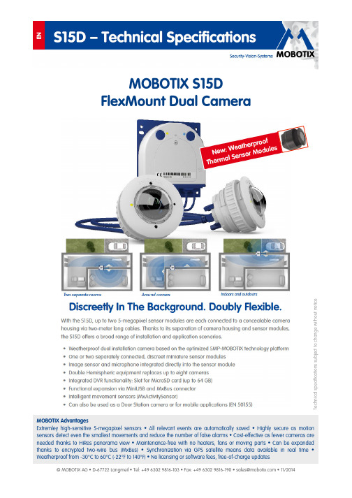
MOBOTIX S15DFlexMount Dual CameraMOBOTIX AdvantagesExtremley high-sensitive 5-megapixel sensors • All relevant events are automatically saved • Highly secure as motion sensors detect even the smallest movements and reduce the number of false alarms • Cost-effective as fewer cameras are needed thanks to HiRes panorama view • Maintenance-free with no heaters, fans or moving parts • Can be expanded thanks to encrypted two-wire bus (MxBus) • Synchronization via GPS satellite means data available in real time • Weatherproof from -30°C to 60°C (-22°F to 140°F) • No licensing or software fees, free-of-charge updatesT e c h n i c a l s p e c i fic a t i o n s s u b j e c t t o c h a n g e w i t h o u t n o t i ceFor more information on the entire range of MOBOTIX accessories and additional information on the S15D, such as prices, manuals, video management software for computers and iOS devices, etc., please go to > Products. Or - if you would like to talk to us on the phone to get advice with our products, please call +49 06302 9816-103.Camera Model S15D-Sec Lenses, Sensors (Optical, Sensor Modules And BlockFlexMount Sensor Modules)Hemispheric 12 mm (180° x 160°)L12Super Wide-Angle 25 mm (82° x 61°)L25Wide-Angle 38 mm (55° x 41°)L38Wide-Angle 51 mm (40° x 30°)L51Tele 76 mm (27° x 20°)L76Tele 160 mm (13° x 10°)L160Tele 320 mm (7° x 5°)BlockFlexMount only CSVario 28 – 63 mm (28° – 58°)BlockFlexMount only Image sensor with individual exposure zones (B/W sensor modules also available with integrated Long Pass Filter)Color, B/W (any combination)Sensor sensitivity in lux at 1/60 s /1 sColor: 0,25/0,013 B/W: 0,005/0,0025Image sensor resolution (each color or B/W sensor)5MP (2592 x 1944) Thermal Sensor Modules For S15D see pages 7 to 9Hardware FunctionsProtection class (camera body)IP65 Temperature range -30 to +60°C/-22 to +140°F•Temporary internal DVR64 MB Internal DVR, ex works 4 GB (MicroSD) Microphone (in sensor modules)/speaker•/–Passive infrared sensor (PIR)–Integrated temperature sensor•Shock detector•Power consumption (typical) with one/two sensor module(s, not with thermal sensor modules< 4,5 watts/< 5 watts Variable PoE class (factory default: class 3, with thermal sensor module class 3 always necessary) 2 or 3 Image Formats, Frame Rates, Image StorageMaximum image format (per sensor)5MP (2592 x 1944) Maximum frame rate (MxPEG, max. resolution)10 fps (5MP) CIF images with 4 GB MicroSD DVR250,000VGA images with 4 GB MicroSD DVR125,000HD images with 4 GB MicroSD DVR40,000 QXGA images with 4 GB MicroSD DVR20,000• available ex works– not availableCamera Model S15D-Sec General FuncrionsDigital zoom (continous) with panning•Codecs: Motion-JPEG/MxPEG/H.264 for SIP•/•/•Programmable exposure zones•Snapshot recording (pre/post-alarm images)50 Terabyte ring buffer storage (internal/network)•Continous recording with sound (0.2 to 30 fps)•Event recording with sound•Time and event control/flexible event logic•/•Weekly schedules/holidays•Web functionality (FTP, email)•Playback/QuadView and MultiView•/•Bidirectional sound in browser – extra speaker needed*•Logo generator, animated•Master/Slave arming•Several scheduled privacy zones•Customized voice messages – extra speaker needed*•VoIP telephony (audio/video, alert) – extra speaker needed*•Remote alarm notification (network message)•Signal inputs/outputs and RS232 via MX-232-IO-Box Programming interface (HTTP API)•Security Features•(HTTPS/SL, IP-based access control, IEEE 802.1X network authentification)Video AnalysisVideo motion detector•MxAnalytics–MxActivitySensor•Video Management SoftwareMxEasy (Windows/Mac OS X)•MxControlCenter (Windows)•MOBOTIX App (iOS)•* Niote: No integrated microphone in a thermal sensor moduleS15D Core (Basis odul )1.11.111.8 1.71.61.31.41.101.91.21.5M.6M.3M.2M.1M.7M.8M.5M.4M.10M.9(Excerpt from the technical documentation: > Support > Manuals)54.0130.039.0Ø5.517.3100.0100.08.5Ø7.033.510.0115.016.0Ø19.030.0110.0106.047.515.037.05.019.124.544.0103.0Ø5.5Ø4.0BottomSideTopFrontExample with L12 Sensor, ceiling mount.Each extension gives you 40mm more space.You can use more than one on every sensor.Ø45.0Ø45.0Ø45.0+ 2x 40m m = 85+ 40m m = 45m a x 5m m(Excerpt from technical drawings and 3D views: > Support > Image Database)Delivered Parts S15D Core (Basis Module)Pressure compen-sationBase plateRLLEDs MicroSD cardKeysTriple cable retainerBayonet catch S15D housing cover Sensor modulesMiniUSBEthernet patch cableEthernet installation cable or MxBus, microphone, speakerMOBOTIX-RJ45 or MxBus, microphone,speakerLSA+ terminal Ethernet Installationcable Screw terminals MxBus, microphone,speaker(S15D – Camera housing and connectors, excerpt from the technical documenation)Thermal Sensor Modules For The S15DThe world’s first flexible dual thermal cameraThe thermal sensor modules measure the thermal radiation ofobjects, so that they can function in absolute darkness. Togetherwith the MxActivitySensor, they can reliably detect motion inimages at night. Only changes in position trigger a signal. Objectsmoving on the spot do not trigger a signal. The thermal sensormodules also have an advantage during the day since they candetect moving objects in shadows, semi-darkness, smoke, orbehind bushes.The MOBOTIX thermal sensor modules are designed for around-the-clock operation in industrial conditions and are certified asweatherproof according to IP66. Just like for the daylight modules,there are different focal lengths available for the thermal modules:•MX-SM-Thermal-L43 with a horizontal image angle of 45°•MX-SM-Thermal-L65 with a horizontal image angle of 25°•MX-SM-Thermal-L135 with a horizontal image angle of 17°The S15D with thermal sensor module(s) in a weatherproof aluminum housing is the world’s first flexible dual thermal camera. This is because, as is typical for the S15D, the new thermal sensor modules are also flexibly connected with the familiar, max. two-meter-long sensor cables to the camera housing, which makes efficient installations and customer-specific special installations very easy.Figure: One camera secures two surveillance areas, for example 90° around a corner, indoor and outdoor areas, two areas with different focal lengths, left/right side.The following thermal sensor module combinations are possible with the S15D:A. Mixed operation (1 x thermal sensor module, 1 x 5 MP sensor module):The advantages of an S15D with a thermal sensor module and simultaneous daylight sensor lie in theandinthehoursandduringtwilightdayofcombinationbothimages:5-megapixelbrilliantimagesreliable motion detection at night.B. Dual thermal operation (2 x thermal sensor module – only possible with the S15D, not with the M15D-Thermal):Two thermal images of two different image areas with just one cameraC. Single thermal operation (1 x thermal sensor module):One thermal image, thermal sensor module with flexible mountingB. C.A.Retrofit or upgrade with thermal technology is possible at any timeIn combination with the camera firmware version 4.2.1.43 or higher, every S15D can operate with thermal sensor modules and be converted into a high-end thermographic camera.Maximum spacing between surveillance camera and detected object with the thermal sensor modules L43 to L135: Recognition criteria according to EN 50132-7L43 / 45°L65 / 25°L135 / 17°Monitoring of humans52 m95 m144 mDetection of humans26 m47 m72 mMonitoring of cars150 m275 m400 mDetection of cars58 m140 m200 mHighly sensitive thermal sensor with NETD typically 50 mK (visualizes temperature differences starting at 0.05°C/0.09 °F)Unlike cameras with 5 MP image sensors, one of the decisive quality criteria for a thermal camera is not the image resolution, measured in pixels, but rather the camera’s ability to capture the slightest differences in temperatureand to produce an image that displays these differences in colors. The sensitivity of a thermal sensor is measuredin millikelvin by the NETD, or Noise Equivalent Temperature Difference. MOBOTIX thermal cameras offer a sensorvalue of 50 mK, which places them in the top range.Warehouse:Thanks to an NETD of 50 mK,the MOBOTIX thermal image(left) shows more details thana less powerful thermographiccamera with an NETD of 100mK (right)T echnical data - Thermal sensor modules for S15DModel versionsMX-SM-Thermal-L43/L65/L135, dual operation with an additional thermal sensor or MX sensor module (5 MP) possible on the S15D Lens options for thermal image sensor L43: 45°, L65: 25°, L135: 17° (horizontal image angle)Sensitivity - thermal image sensor NETD typically 50 mK (equivalent to 0.05 °C/0.09 °F), < 79 mK Image sensor for thermal image sensor Uncooled microbolometer with 336 x 252 pixelsTemperature measurement range -40 °C to +550 °C/-40 °F to +1022 °F (temperature of objects to be detected)Spectral range7.5 to 13.5 μmMaximum image size for thermal image sensorScalable up to 2592 x 1944 (5MP), automatically scaled to the image size of the MX sensor module with dual imagesMaximum frame rate for thermal image sensor9 fps (the camera’s overall frame rate is reduced to a maximum of 9 fps when an MX sensor module and a thermal image sensor are displayed simultaneously)Software functions for thermal image sensor (certain features only available with firmware version 4.2.1.43 and higher)Optional off-color or black and white image, image mirroring, obscure image area, PTZ commands (pan, tilt, zoom), text and logo options, show event/action symbols, level displays in bars or diagrams, temperature control windowPower consumption for S15D with one/two thermal sensor module(s)Typically 1.5 W per thermal sensor module; however, can only be used together with an S15D camera housing (versions A to C):A. Mixed operation (1 x thermal, 1 x optical): typically 6.5 W (7.5 W possible over the short term)B. Dual thermal operation (2 x thermal): typically 7 W (8 W possible over the short term)C. Single thermal operation (1 x thermal): typically 5.5 W (6.5 W possible over the short term)Operating conditions IP66, -30 °C to +60 °CMaterialModule housing: black anodized aluminum; pressure plate: V2A stainless steel; lens and protective glass lens: germaniumWeight / length / installationdimensions Thermal sensor modulesWeight: < 330 g (one thermal sensor module without sensor cable); total length: 78 mm; diameter of front panel: 57 mm; diameter of stainless steel pressure plate: 63 mm; bore diameter: 48 – 53 mm; maximum wall thickness for installation: 14 mm; alternativemounting with six screw threads on the side of the module for M4 screws, 4 mm thread depthDelivered partsThermal sensor module, 3 mm Allen wrench used to install the pressure plate, QuickInstall guide - the S15D camera housing (S15D-FlexMount Core) and sensor cable must be ordered separately!NOTE: An S15D with one or two thermal sensor modules always requires PoE class 3 (factory default).Attention – Special Export Regulations For Thermal Cameras Apply!Cameras with thermographic image sensors (“thermal cameras”) are subject to the specialexport regulations of the U.S.A. and the ITAR (International Traffic in Arms Regulation):• According to the currently applicable export regulations of the U.S.A. and the ITAR, cameras with thermographic image sensors or parts thereof must not be exported to countries embargoed by the U.S.A. or the ITAR. At present, this applies to the following countries: Syria, Iran, Cuba, North Korea and Sudan. The same export ban applies to all persons and institutions listed in “The Denied Persons List” (see , “Policy Guidance > Lists of Parties of Concern”).• Under no circumstances can the camera itself or its thermographic image sensors be used in the design, the development or in the production of nuclear, biological or chemical weapons or in the weapons themselves.。
Panasonic WV-S1131 高质量的自动对焦摄像头说明书
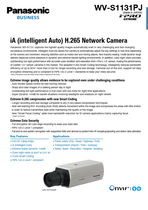
Lens not includedPanasonic WV-S1131 captures the highest quality images automatically even in very challenging and fast-changingsurveillance environments. Intelligent Auto (iA) allows the camera to automatically adjust the key settings in real-time depending on the scenery and movement, reducing distortion such as motion blur and moving objects. New industry-leading 144dB dynamic range delivers balanced scene exposure in dynamic and extreme-backlit lighting environments. In addition, color night vision provides outstanding low-light performance with accurate color rendition and saturation from i-Pro's 1/3" sensor, rivaling the performance of costlier 1/2" sensor cameras in the market. The adopted H.265 Smart Coding technology, intelligently reduces bandwidth efficiency of up to 95%* more than H.264 for longer recording and less storage. Cameras out-of-the-box, support full data encryption streaming and is compliant to FIPS 140-2 Level 1 standards to keep your video secured.*Value in Advanced mode with Smart Facial Coding. It depends on the scene.Extreme image quality allows evidence to be captured even under challenging conditions-Auto Shutter speed control for fast moving vehicles -Sharp and clear images of a walking person day & night-Outstanding low light performance in true color with low noise for night time applications-Super Dynamic 144dB for backlit situations involving headlights and shadows on night streetsExtreme H.265 compression with new Smart Coding-Longer recording and less storage compared to any H.264 based compression techniques-New self-learning ROI* encoding (Auto VIQS) detects movement within the image and compresses the areas with little motion in order to reduce transmitted data while maintaining the quality of the image.-New “Smart Facial Coding” adds more bandwidth reduction for ID camera applications mainly capturing faces*Region of InterestExtreme Data Security-Full encryption SD card edge recording to keep your data safe -FIPS 140-2 Level 1 compliant-Full end-to-end system encryption with supported VMS and devices to protect from IP snooping/spoofing and detect data alterationiA (intelligent Auto) H.265 Network Camera•Full HD 1080p 60fps •iA (intelligent Auto)•Extreme Super Dynamic 144dB •Color night vision (0.0007 to 0.01 lx)•H.265 Smart Coding•FIPS 140-2 Level 1 compliantKey Features•Public safety (City / Road / Highway / Port)•Transportation (Airport / Train / Subway)•Retail / Bank / Education / Hospital / BuildingApplicationsWV-S1131PJ(Made in JAPAN)DISTRIBUTED BY :https:///PanasonicNetworkCamera(2A-170DA)Trademarks and registered trademarks– iPad and iPhone are registered trademarks of Apple Inc.– Android is a trademark of Google Inc.– ONVIF and the ONVIF logo are trademarks or registered trademarks of ONVIF Inc.– All other trademarks identified herein are the property of their respective owners.• Masses and dimensions are approximate. • Specifications are subject to change without notice.Important– Safety Precaution : Carefully read the Important Information, Installation Guide and operating instructions before using this product.– Panasonic cannot be responsible for the performance of the network and/or other manufacturers' products used on the network.Specifications*2 Super Dynamic function is automatically set off on 60 fps mode.*3 Stabilizer, Smart Facial Coding, i-VMD can not be used at the same time.*4 When “3 mega pixel [4 : 3](30fps mode)” is selected for “Image capture mode”, “90 °” and “270 °” cannot be selected.*5 Used by super resolution techniques*6 Transmission for 4 streams can be individually set.*7 Only use AAC-LC (Advanced Audio Coding - Low Complexity) when recording audio on an SD memory card.*8 Including alarms from Plug-in SoftwareAppearanceOptional AccessoryUnit : mm (inches)Notification sent to the monitoring screen。
波士顿安全DINION IP Starlight 8000 MP摄像头说明书

The DINION IP starlight 8000 MP camera provides clear images 24/7 – even at night or under low-light conditions.High sensitivity in color (0.022 lx at 5MP and even0.013 lx at 1080p) enables this camera to work with a minimum of ambient light. This exceptional light sensitivity combined with Content-Based Imaging Technology (C-BIT) ensures crisp, clear, detailed images in all lighting conditions.System overviewCompared to HD cameras, the DINION IPstarlight 8000 MP offers much higher resolution, best-in-class sensitivity, highest frame rates for MP camerasin the industry, and highly usable images even in low-light and HDR scenes. And yet the camera is bandwidth efficient due to the state-of-the-art sensor, the intelligent noise reduction and advanced compressor.FunctionsExceptional low-light performanceThe latest sensor technology combined with the sophisticated noise suppression results in a sensitivity of 0.022 lx at full 5MP resolution in color. The low-light performance. In IVA versions, the intelligent Automatic Exposure (iAE) technology, for example, allows you to view moving objects in bright and dark areas of a scene.iDNR reduces bandwidth and storage requirements The camera uses intelligent Dynamic Noise Reduction (iDNR) which actively analyzes the contents of a scene and reduces noise artifacts accordingly.The low-noise image and the efficient H.264 compression technology provide clear images while reducing bandwidth and storage by up to 30% compared to other H.264 cameras. This results inreduced-bandwidth streams that still retain a high image quality and smooth motion. The cameraprovides the most usable image possible by cleverly optimizing the detail-to-bandwidth ratio.Area-based encoding is another feature which reduces bandwidth. Compression parameters for up to eight user-definable regions can be set. This allowsuninteresting regions to be highly compressed, leaving more bandwidth for important parts of the scene.allows fast and easy configuration. Nine configurable user modes are provided with the best settings for a variety of applications:•Indoor – general day-to-night changes without sun highlights and street lighting (e.g. office environments)•Outdoor – general day-to-night changes with sun highlights and street lighting•Night optimized –optimized for sufficient details at low light (at the cost of a lower frame rate and more motion judder)•Low bit rate – optimized bandwidth (at the cost of reduced contrast, less detail and less sharpness)•Intelligent AE – optimized for scenes with moving objects against bright lights (this mode will switch to BLC if no IVA is available)•Vibrant – similar to Indoor mode with enhanced contrast, sharpness and saturation (at the cost of a higher bit rate and less details visible in darker areas)•Sports and Gambling – enhanced color and sharpness (for use in casinos)•Traffic – for monitoring traffic movement at roads,Cloud-based servicesThe camera supports time-based or alarm-based JPEG posting to four different accounts. These accounts can address FTP servers or cloud-based storage facilities (for example, Dropbox). Video clips or JPEG images can also be exported to these accounts.Alarms can be set up to trigger an e-mail or SMS notification so you are always aware of abnormal events.Access securityPassword protection with three levels and 802.1x authentication is supported. To secure Web browser access, use HTTPS with a SSL certificate stored in the camera. The video and audio communication channels can be independently AES encrypted with 128-bit keys by installing the optional encryption site plete viewing softwarelighting conditions.Easy installationPower for the camera can be supplied via a Power-over-Ethernet compliant network cable connection.With this configuration, only a single cable connection is required to view, power, and control the ing PoE makes installation easier and more cost-effective, as cameras do not require a local power source.The camera can also be supplied with power from +12 VDC power supplies. To increase system reliability, the camera can be simultaneously connected to both PoE and +12 VDC supplies.Additionally, uninterruptible power supplies (UPS) can be used, which will allow continuous operation, evenduring a power failure. For trouble free network cabling, the cameras support Auto-MDIX.Varifocal SR Megapixel LensRugged varifocal SR megapixel IR corrected lens.1/1.8” sensor; CS-mount; 4-pin SR-iris; 5MP;4.1 to 9 mm; F1.6 to F2.4Order number LVF-5005C-S4109AccessoriesMonitor Cable SMB 0.3MAnalog monitor cable SMB (female) to BNC (female).0.3 meterOrder number NBN-MCSMB-03MMonitor Cable SMB 3.0MAnalog monitor cable SMB (female) to BNC (male).3 meterRepresented by:Americas:Europe, Middle East, Africa:Asia-Pacific:China:America Latina:Bosch Security Systems, Inc. 130 Perinton Parkway Fairport, New York, 14450, USA Phone: +1 800 289 0096 Fax: +1 585 223 9180***********************.com Bosch Security Systems B.V.P.O. Box 800025617 BA Eindhoven, The NetherlandsPhone: + 31 40 2577 284Fax: +31 40 2577 330******************************Robert Bosch (SEA) Pte Ltd, SecuritySystems11 Bishan Street 21Singapore 573943Phone: +65 6571 2808Fax: +65 6571 2699*****************************Bosch (Shanghai) Security Systems Ltd.201 Building, No. 333 Fuquan RoadNorth IBPChangning District, Shanghai200335 ChinaPhone +86 21 22181111Fax: +86 21 22182398Robert Bosch Ltda Security Systems DivisionVia Anhanguera, Km 98CEP 13065-900Campinas, Sao Paulo, BrazilPhone: +55 19 2103 2860Fax: +55 19 2103 2862*****************************© Bosch Security Systems 2014 | Data subject to change without notice 12535909643 | en, V1, 29. Jan 2014。
马歇尔1.3叁兆像素摄像头说明书

Features, specifications, pricing, and dimensions are subject to change without notice. Physical appearance of products may vary slightly from images shown on this document. Please visit our website for updates and information.
13. PoE+
MEGAPIXEL
POWER OVER ETHERNET VANDAL -PROOF
......
IR IP66
.....
......
......
INGRESS PROTECTIO N ILLUMINATION SUPER LOW LIGHT
• 1.3 Megapixel 1/3” Progressive Scan Panasonic CMOS • Max. 30fps @ 1280 x 1024 • Min. 0.03Lux(color), 0.02Lux(B/W) • Auto Iris varifocal lens (f=3 ~ 9mm, F1.4) built-in • Mechanical IR cut filter for True Day & Night (ICR) • HSBLC (Highlight Suppression Backlight Compensation) • Superior Low Light Performance • Powerful Demist (anti-fog Algorithm) • 3D Noise reduction • Privacy Masking • Dual Streaming (H.264/H.264, H.264/MJPEG) • PoE (Power over Ethernet): 802.3af • Composite Video Output • 3-Axis internal camera bracket • SD/SDHC slot for local storage • Compliant with ONVIF, PSIA • Excellent low light performance
博顺 MIC IP dynamic 7000 HD 监控摄像头说明书

u强度和坚固性非常优异,适用于室外、工业或商业监控应用场合u 宽动态范围 (HDR),同时呈现亮区和暗区细节u可选、现场安装的组合照明灯(红外灯/白光)使您最多可探测到 175 米(575 英尺) 远的物体u使用了新的铰链式 DCA 安装附件和新型缆线设计,安装极为简单u符合 ONVIF 标准;与其它符合该标准的系统具有互操作性。
MIC IP dynamic 7000 HD 摄像机具有先进的 PTZ 平台,此平台采用博世在材料工程、机械设计、智能成像和视频流方面的专业领域知识设计而成。
该摄像机符合某些严格的业界标准(例如,IP68、NEMA 6P 和 IK10),具有相当出色的机械强度和耐久性。
该摄像机采用智能成像和视频流方面的全新技术设计而成。
凭借智能编码和基于内容的成像技术(CBIT),即使在比特率非常低、光照条件极具挑战性的情况下,高清模块也能提供高清晰度视频。
功能结实耐用的设计,适用于极端应用场合该摄像机被设计为可在传统定位系统的机械性能无法应付的监控应用场合中持续使用。
整个金属机身经过精心设计,能承受高强度冲击或持续的低频振动。
该摄像机型号在耐冲击性方面符合IK10标准,在抗震动和撞击方面符合IEC 60068标准。
该摄像机具有-40°C 至 +60°C (-40°F 至 +140°F )的温度范围,专门设计用于世界各地的极端环境。
该摄像机在材料工程和涂层方面受益于博世所在领域的知识。
因此,专业的冶金技术和涂层为摄像机提供了强大的防腐蚀保护。
摄像机已经过2000小时的盐雾测试(按照ASTM B117标准)。
Intelligent Defog用户可以将模式配置为连续处于活动状态,也可以配置为在摄像机中的视频分析功能检测到雾时自动激活该模式并向视频图像添加光度(当雾散去或场景变化时,随即停用该模式)。
集成刮水器凭借集成的长寿命硅胶刮水器,无论天气冷热,MIC 摄像机一年四季均能捕获高品质的图像。
MD-013 GNSS(GPS、GLONASS、Galileo) disciplined oscil

MD-013GNSS (GPS, GLONASS, Galileo) Disciplined Oscillator ModuleThe MD-013 is a Microchip standard platform module that provides 1 pps TTL,10 MHz sine wave and 10 MHz square wave outputs that aredisciplined to an embedded 72 channel GNSS Receiver. In addition, an external reference input can override the internal receiver as thereference. Internal to the module is a Microchip digitally corrected OCXO.• Embedded GNSS Receiver - GPS, GLONASS, Galileo • 1pps TTL output signal• 10MHz sinewave and square wave output • Other RF output frequencies available• Adaptive aging correction during holdover • Barometric pressure correction • Evaluation kit with software• Serial Communications Interface • NMEA 0183 V4.1• Basestation Communication • Digital Video Broadcast • E911 Location Systems• General Timing and Synchronization • Military Radio • Radar SystemsFeaturesBlock DiagramApplicationsQuartz Oscillator(OCXO)Processor/ControllerOutput Frequency GenerationAntenna Input1PPS OutputRF Output(10 MHz standard - other frequencies available)SerialFigure 1. Functional Block DiagramOutput Locked Module OKGNSS ReceiverHardwareResetManual Holdover External ReferenceInputSpecificationsGPS AntennaParameter Min Typical Max Units Condition Antenna Bias Voltage 4.0 4.8 5.1VDCAntenna Current620100mARF Output Waveform Characteristics (via MCX)Parameter Min Typical Max Units Condition Waveform SinewaveOutput Power+3.0+9.0+11.0dBm50 Ohm Harmonics-30dBc50 Ohm Spurious-70dBc50 OhmRF Output Waveform Characteristics (via pin 8)Waveform HCMOSHigh Level Output Voltage (VOH ) 4.0 5.0VDC<-0.5mA LoadLow Level Output Voltage (VOL )0.00.4VDC<0.5mA LoadRise/Fall Time35nSec15 pFDuty Cycle405060%15 pF1pps Output Characteristics (via MCX and pin 2)Parameter Min Typical Max Units ConditionWaveform TTLHigh-level output voltage (VOH) 3.0 5.0V DC50 OhmsLow-level output voltage (VOL)0.00.4V DC50 Ohms Pulse Width9.91010.1uSec default setting, user programmableExternal 1PPS Reference Input (Pin 1)Waveform TTLHigh-Level Output Voltage (VOH) 2.0 5.0V DC50 Ohms input impedanceLow-Level Output Voltage (VOL)0.00.4V DCPulse width10uSecNotes:• RF and 1pps input and output connectors are MCX type (SMA, SMB, MMCX connectors require additional part numbers).• Keyed connector is Samtec FTSH-108-01LDVK type.• Dimensions: mm• Module height in part number is the sum of oscillator height, board, and clearancePackage OutlineAlthough ESD protection circuitry has been designed into the MD-013 proper precautions should be taken when handling and mounting.Microchip employs a human body model (HBM) and a charged-device model (CDM) for ESD susceptibility testing and design protectionReliabilityMicrochip qualification includes aging various extreme temperatures, shock and vibration, temperature cycling, and IR reflow simulation. The MD-013 family is capable of meeting the following qualification tests:J3J9Ordering Information InstructionsCustomization to unique customer requirements is available and is common for this level of integration. Common customizations include alternate output frequencies, temperature ranges, differing values and methods of hold over specification, and holdover optimization in the frequency domain. The table below lists exisiting combinations available as of the date of publication of this data sheet. Please contact the factory for additional options.Ordering InformationMD - 013 3 - B X E - 15E7 - 10M0000000Product FamilyMD: Precision ModulesPackage 65x115mm Height 3: 19.5 mmSupply Voltage B: +12VHold Over15E7: 1.5 µs hold over option 40E7: 4.0 µs hold over optionFrequencyRF Output Code X: standard outputs per specificationTemperature Range E: -40°C to +85°C1) Holdover and aging performance is after 7 days of power-on time. Temperature and aging rates are whendevice is not locked. Performance measured in still air.2) After customer applies correct offset using cable delay command while locked, after 24 hours of locked opera-tion3) ADEV at t =86400s while locked to GPS, after 24 hours of locked operation4) The status locked indicator is intended to indicate when the module is fully locked to a reference.5) The Hardware OK indicator is intended to indicate when the module is operating properly without any failures, including hardware, software or parameter out of range.6) Antenna over current flag will be set if maximum current is exceeded. Circuit has overcurrent protection.7) The Rx pin is the serial interface input and the Tx pin is the serial interface output. The serial interface shall operate at 115,200 baud with eight (8) data bits, one (1) stop bit and no parity.USA:100 Watts StreetMt Holly Springs, PA 17065Tel: 1.717.486.3411Fax: 1.717.486.5920Europe:Landstrasse74924 NeckarbischofsheimGermanyTel: +49 (0) 7268.801.0Fax: +49 (0) 7268.801.281Information contained in this publication regarding device applications and the like is provided only for your convenience and may be superseded by updates. It is your reasonability to ensure that your application meets with your specifications. MICRO-CHIP MAKES NO REPRESENTATION OR WARRANTIES OF ANY KIND WHETHER EXPRESS OR IMPLIED, WRITTEN OR ORAL, STATUTORY OR OTHERWISE, RELATED TO THE INFORMATION INCLUDING, BUT NOT LIMITED TO ITS CONDITION, QUALITY, PERFORMANCE, MERCHANTABILITY OR FITNESS FOR PURPOSE. Microchip disclaims all liability arising from this information and its use. Use of Microchip devices in life support and/or safety applications is entirely at the buyer’s risk, and the buyer agrees to defend, indemnify and hold harmless Microchip from any and all damages, claims, suits, or expenses resulting from such use. No licenses are conveyed, implicitly, or otherwise, under any Microchip intellectual property rights unless otherwise stated.。
SEN012DG;SEN013DG;SEN012DG-TL;SEN013DG-TL;中文规格书,Datasheet资料
SEN012-013SENZero Family November 2010Zero 1 Loss High Voltage Sense Signal Disconnect IC®Product HighlightsFeatures and Performance• Eliminates significant standby losses• Disconnects unnecessary circuit blocks during standby, remote-off, or light-load conditions• Ultra low leakage (maximum 1 m A) 650 V MOSFETs • <0.5 mW per channel during standby• Single component provides remote disconnect functionality• No external components or additional bias supply needed for remote-off• Integrates multiple disconnect MOSFETs, gate drive, and protection• Minimal component count provides higher reliability• Protection features to help production/manufacturing yields • Pin-to-pin fault and ESD protection• Triggerable via remote-off signal or load conditions• Integrated gate pull down circuit protects against loss of trigger signal fault• Green package technology• RoHS compliant and halogen free• Withstands high differential surge conditions• S1, S2 and S3 interface with controller pins up to 6.5 V above system ground EcoSmart ® – Energy Efficient• <3 mW loss at 230 VAC in Off/standby modeApplications• ACDC converters with high-voltage resistive signal paths • Ideal for all very low standby systems such as those meeting EuP Lot 6 and similar energy efficiency standardsDescriptionSENZero is a compact low cost solution to eliminate losses in resistive signal paths connected between high-voltage rails and switching power supply controller(s). Examples include feed-forward or feedback signal paths connected to boost controllers in power factor corrected systems and feedforward signal paths in two switch forward / LLC / half and full bridge converters.The device is available in 2 (SEN012) and 3 (SEN013) channel versions according to the application’s requirements. The internal gate drive and protection circuitry provides gate drive signals to the internal 650 V MOSFETs in response to the voltage applied to the VCC pin. This simple configuration provides easy integration into existing systems by using the system V CC rail as an input to the SENZero.The SENZero family uses a low cost compact SO-8 package to reduce PCB area while the pin configuration is designed to meet pin-pin fault conditions.Figure 2.Typical Application SEN013.Figure 1.Typical Application SEN012.PI-5812-032510V CC SignalTo Controller(s)Sense PinsPI-5813-032510V CC SignalTo Controller(s)Sense PinsComponent Selection TableProduct2Integrated DisconnectMOSFETs230 VACPower Consumptionin StandbySEN012DG 2<1 mW SEN013DG3<1.5 mWTable 1. Component Selection Table. Notes:1. IEC 62301 clause 4.5 rounds standby power use below 5 mW to zero.2. Package: D: SO-8.Rev. B 11/05/10Figure 3. SENZero Functional Block DiagramFigure 4. Pin Configuration.Figure 5. Typical R DS(ON) as a Function of V CC -V S Voltage.Figure 6. Typical R DS(ON) as a Function of V S Voltage.Pin Functional DescriptionSOURCE (S1, S2, S3) Pins :Internally connect to the SOURCEs of MOSFETs 1, 2 and 3 respectively.DRAIN (D1, D2, D3) Pins :Internally connect to the DRAINs of MOSFETs 1, 2 and 3 respectively.VOLTAGE SUPPLY (VCC) pinThe internal MOSFETs are fully turned on when the VCC pin voltage is V CC(ON) (see parameter table) or more greater than their SOURCE voltage relative to GROUND. VCC pin should be connected to GROUND to turn the MOSFETs off.GROUND (G) Pin:This is the ground reference for all the SENZero pin voltages.4671110859V CC -V S (V)R D S (O N ) (Ω)65060055050045040035030001347625V S (V)R D S (O N ) (Ω)550500450400350Rev. B 11/05/10Applications ConsiderationsThe maximum voltage that the device can sustain across the VCC and G pin is 16 V. The maximum voltage that any of the source channels can be at with respect to the ground terminal is 6.5 V. SENZero has a typical on state resistance of approxi-mately 500 W at room temperature. The device is therefore typically used in series with high ohmic value resistors where this on resistance is a small percentage of the total series impedance.It is not necessary to provide a local bypass capacitor on the VCC pin.Operating Configurations for the SENZeroOne configuration to power up the SENZero is shown in Figure 7. In this circuit, SENZero is powered up from an unregulated bias winding through a simple series pass regulator formed by Q1, R B and V Z . This configuration ensures the VCC voltage is limited even if the maximum bias voltage exceeds 16 V. During power down, as soon as the bias voltage falls below V Z , SENZero will turn off.The series pass transistor Q1 is necessary only if the bias winding voltage regulation is not tight enough (unregulated). If the voltage on the bias winding is regulated or is such that the voltage on the VCC pin can be maintained in the range 6 V < VCC < 16 V, then the series pass transistor (Q1, R B and V Z ) can be eliminated.Figure 7. SENZero Powered from an Unregulated Bias Winding Through a Series Pass Regulator. Device is Enabled When Bias Voltage is Present.A configuration that can be used to trigger remote-off functionality is shown in Figure 8. In this configuration, a regulated auxiliary output is used to power the IC. Transistor Q1 serves as the ON/OFF switch which is commanded by the Enable/Disable signal at its base.Figure 8. SENZero Powered From a Regulated Auxiliary Winding.An alternative remote-off configuration is shown in Figure 9 where an unregulated bias voltage supplies the SENZero through a series pass regulator similar to the one shown in Figure 7. However the circuit of Figure 9 includes an ON/OFF transistor Q2. In other versions of this circuit Q2 can bereplaced by an optocoupler allowing the ON/OFF disable signal to be communicated from a secondary of the power supply such as in PC power supplies.Figure 9.A Modified Version of an Unregulated Bias Winding Supplying Power Through a Series Pass Regulator. Transistor Q2 Provides Remote-Off Functionality.Rev. B 11/05/10Application ExampleSENZero in PFC Bus Voltage Feedback Network Commercial PFC IC’s typically has a pin dedicated for sensing the output voltage of the PFC Stage. The information on this pin is typically used by the PFC IC for various major functions.1. Output regulation – input to the non-inverting input of theerror amplifier2. OVP detection - input to the OVP comparator3. Open loop protection – used to detect open loop conditions The last 2 functions were used for protecting the bus from overvoltage condition.Figure 10. PFC Bus Voltage Sense Network.The SENZero objective is to eliminate the losses associated with the sense resistors without affecting the functionality of the circuit. To keep the operation of the PFC IC unaffected, SENZero and PFC on and off event must follow the required timing sequence during power-up, power-down, remote-on, and remote-off event.PI-6205-102510PS PI-6206-102510Figure 11. Timing between PFC IC and SENZzero during Power-up and Power-Down.In case of shared VCC Connection, it must be ensure that SENZero have a lower turn-on and turn-off threshold voltage compared to the PFC IC.Figure 12. Timing between PFC IC and SENZero with PS (ON) Signal.From off-state to on-state, SENZero must turn-on ahead of the PFC. From on-state to off-state, PFC must shutdown ahead of the SENZero. This is to ensure that whenever PFC is operating (switching), SENZero is invincible to the PFC. SENZero only disconnects the sense resistors when PFC is in off-condition and thus eliminates its associated losses during standby condition.Rev. B 11/05/10Figure 13. Typical Connection with PS (ON) Signal.The figure above shows a typical VCC arrangement to satisfy timing requirements.Transistor QA is enabled during remote on condition. Capacitor C2 will charge through D1 while C1 is charged through R1. SENZero will turn on ahead of PFC IC. Diode D2 makes C2 voltage tracks C1 voltage. Capacitor C2 can be increased to ensure that during turn-off, PFC turns-off first before SENZero.Capacitors C1 and C2 can be 100 nF standard decoupling capacitors. However, C1 needs to be ≥C2.Rev. B 11/05/10NotesA. This is the minimum voltage difference required between V CC and the highest of voltages V S1, V S2 and V S3 to achieve the R DS(ON)specification in the parameter table. As an example, if S1 externally connects to a controller pin having a voltage of 4 V relative to G pin, V CC(ON) of 5 V will be achieved by having at least (5 V + 4 V) = 9 V applied to the SENZero VOLTAGE SUPPLY (VCC) pin relative to the G pin.B. Per channel.C. Between Ground and Drain of individual MOSFET under test.D. Guaranteed by design.Absolute Maximum Ratings (1)DRAIN Pin Voltage (D1, D2, D3) ..............................-0.3 V to 650 V VCC Pin Voltage ...................................................-0.3 V to 16 V Voltage on S1, S2, S3 Pins ..................................-0.3 V to 6.5 V Storage Temperature ......................................-65 °C to 150 °C Operating Junction Temperature ......................-40 °C to 125 °C Lead Temperature (2) .........................................................260 °CNotes:1. All voltages referenced to Ground, T A = 25 °C.2. 1/16 in. from case for 5 seconds.Rev. B 11/05/10Part Ordering Information• SENZero Product Family • SENZero Series Number • Package IdentifierD Plastic SO-8• Package MaterialG GREEN: Halogen Free and RoHS Compliant • Tape & Reel and Other OptionsBlankStandard Configurations TLTape & ReelSEN 012 D G - TLPart Number Options Quantity SEN012DG Tube 98SEN012DG-TL Tape and Reel 2500SEN013DGTube98SEN013DG-TL Tape and Reel2500For the latest updates, visit our website: Power Integrations reserves the right to make changes to its products at any time to improve reliability or manufacturability. Power Integrations does not assume any liability arising from the use of any device or circuit described herein. POWER INTEGRATIONS MAKES NO WARRANTY HEREIN AND SPECIFICALLY DISCLAIMS ALL WARRANTIES INCLUDING, WITHOUT LIMITATION, THE IMPLIED WARRANTIES OF MERCHANTABILITY, FITNESS FOR A PARTICULAR PURPOSE, AND NON-INFRINGEMENT OF THIRD PARTY RIGHTS. Patent InformationThe products and applications illustrated herein (including transformer construction and circuits external to the products) may be covered by one or more U.S. and foreign patents, or potentially by pending U.S. and foreign patent applications assigned to Power Integrations. A complete list of Power Integrations patents may be found at . Power Integrations grants its customers a license under certain patent rights as set forth at /ip.htm.Life Support PolicyPOWER INTEGRATIONS PRODUCTS ARE NOT AUTHORIZED FOR USE AS CRITICAL COMPONENTS IN LIFE SUPPORT DEVICES OR SYSTEMS WITHOUT THE EXPRESS WRITTEN APPROVAL OF THE PRESIDENT OF POWER INTEGRATIONS. As used herein:1. A Life support device or system is one which, (i) is intended for surgical implant into the body, or (ii) supports or sustains life, and (iii)whose failure to perform, when properly used in accordance with instructions for use, can be reasonably expected to result in significant injury or death to the user.2. A critical component is any component of a life support device or system whose failure to perform can be reasonably expected to causethe failure of the life support device or system, or to affect its safety or effectiveness.The PI logo, TOPSwitch, TinySwitch, LinkSwitch, DPA-Switch, PeakSwitch, CPAZero, SENZero, EcoSmart, Clampless, E-Shield, Filterfuse, StakFET, PI Expert and PI FACTS are trademarks of Power Integrations, Inc. Other trademarks are property of their respective companies. ©2010, Power Integrations, Inc.Power Integrations Worldwide Sales Support LocationsWorld Headquarters5245 Hellyer AvenueSan Jose, CA 95138, USA. Main: +1-408-414-9200 Customer Service:Phone: +1-408-414-9665 Fax: +1-408-414-9765e-mail: usasales@China (Shanghai)Room 1601/1610, Tower 1 Kerry Everbright CityNo. 218 Tianmu Road West Shanghai, P.R.C. 200070 Phone: +86-21-6354-6323 Fax: +86-21-6354-6325e-mail: chinasales@China (Shenzhen)Rm A, B & C 4th Floor, Block C, Electronics Science and Technology Bldg., 2070 Shennan Zhong Rd, Shenzhen, Guangdong, China, 518031Phone: +86-755-8379-3243 Fax: +86-755-8379-5828e-mail: chinasales@ GermanyRueckertstrasse 3D-80336, MunichGermanyPhone: +49-89-5527-3910Fax: +49-89-5527-3920e-mail: eurosales@India#1, 14th Main RoadVasanthanagarBangalore-560052 IndiaPhone: +91-80-4113-8020Fax: +91-80-4113-8023e-mail: indiasales@ItalyVia De Amicis 220091 Bresso MIItalyPhone: +39-028-928-6000Fax: +39-028-928-6009e-mail: eurosales@JapanKosei Dai-3 Bldg.2-12-11, Shin-Yokohama,Kohoku-kuYokohama-shi Kanagwan222-0033 JapanPhone: +81-45-471-1021Fax: +81-45-471-3717e-mail: japansales@KoreaRM 602, 6FLKorea City Air T erminal B/D, 159-6Samsung-Dong, Kangnam-Gu,Seoul, 135-728, KoreaPhone: +82-2-2016-6610Fax: +82-2-2016-6630e-mail: koreasales@Singapore51 Newton Road#19-01/05 Goldhill PlazaSingapore, 308900Phone: +65-6358-2160Fax: +65-6358-2015e-mail: singaporesales@Taiwan5F, No. 318, Nei Hu Rd., Sec. 1Nei Hu Dist.Taipei, Taiwan 114, R.O.C.Phone: +886-2-2659-4570Fax: +886-2-2659-4550e-mail: taiwansales@Europe HQ1st Floor, St. James’s HouseEast Street, FarnhamSurrey GU9 7TJUnited KingdomPhone: +44 (0) 1252-730-141Fax: +44 (0) 1252-727-689e-mail: eurosales@Applications HotlineWorld Wide +1-408-414-9660Applications FaxWorld Wide +1-408-414-9760Revision Notes DateA Initial Release08/18/10B Added Applications Example section, updated Figure 911/05/10分销商库存信息:POWER-INTEGRATIONSSEN012DG SEN013DG SEN012DG-TL SEN013DG-TL。
达华N53AF5Z星光技术低光环境摄像头说明书
Lite Series | N53AF5ZStarlight TechnologyFor challenging low-light applications, Dahua's Starlight Ultra-low LightTechnology offers best-in-class light sensitivity, capturing color detailsin low light conditions. The camera uses a set of optical features tobalance light throughout the scene, resulting in clear images in darkenvironments.Smart H.265Smart H.265+ is the optimized implementation of the H.265 codec thatuses a scene-adaptive encoding strategy, dynamic GOP, dynamic ROI,flexible multi-frame reference structure and intelligent noise reduction todeliver high-quality video without straining the network. Smart H.265+technology reduces bit rate and storage requirements by up to 70%when compared to standard H.265 video compression.Wide Dynamic RangeThe camera achieves vivid images, even in the most intense contrastlighting conditions, using industry-leading wide dynamic range (WDR)technology. For applications with both bright and low lighting conditionsthat change quickly, True WDR (120 dB) optimizes both the bright anddark areas of a scene at the same time to provide usable video.EnvironmentalSubjected to rigorous dust and water immersion tests and certified to theIP67 Ingress Protection rating makes it suitable for demanding outdoorapplications. The camera offers a wide voltage range, with a 30% inputvoltage tolerance, suitable for external applications with unstable powersources.•1/2.7 in. 5 MP Progressive-scan CMOS Sensor•Triple-stream Encoding•Smart H.265+ and Smart H.264+ Dual Codec•5 MP (2592 x 1944) at 20 fps•2.7 mm to 13.5 mm Motorized Vari-focal Lens•Starlight Technology for Low-light Applications•Analytics+ Function – Perimeter Protection and Smart MotionDetection•True Wide Dynamic Range (120 dB) and Day/Night IR Cut Filter•Maximum IR LED Distance 60 m (196.85 ft)•ArcticPro Series Camera - Operational down to –40° C (–40° F)•IP67 Ingress Protection•Five-year Warranty*System OverviewThe Dahua 5 MP Starlight camera offers Smart Motion Detection forimproved alarm accuracy from intrusion and tripwire functions. Thecamera is ideal for a host of diverse applications — Starlight, True WideDynamic Range, and IR illumination allow the camera to operate in anylighting condition. The camera is a component of the Dahua ArcticProseries and is rated to IP67 allowing the camera to deliver high-qualityand reliable video in the harshest environments.FunctionsPerimeter ProtectionDahua Analytics+ includes Tripwire and Intrusion functions that offercustom tripwires based on object type for automation in limited accessareas. Perimeter Protection requires less pixels to detect an object todeliver improved accuracy and decreased false alarms due to lights,weather, trees, or animals.Smart Motion DetectionSmart Motion Detection, a component of Dahua's Analytics+ technology,improves alarm accuracy and decreases the number of false alarms. Theadvanced SMD algorithm analyzes a scene for human or vehicle motion,while filtering out other motion due to trees, leaves, animals, weather,and triggers an alarm when detected. SMD also saves time whensearching recorded video by filtering false alarms and allowing quickretrieval of an alarm due to a person or vehicle.ArcticProThe Dahua ArcticPro Series of extreme-environment cameras combinetemperature-tolerant components with a waterproof enclosure toensure flawless operation in temperatures as low as –40° C (–40° F)without the need for an internal heater. The lack of a heater reduces thecamera’s power consumption and saves operating costs. For applicationsthat demand high-resolution video with advanced features in extremelycold environments, the Dahua ArcticPro Series offers a camera to satisfythe most demanding requirements.5Mp H.265+Starlight Perimeter1. The DORI distance is a measure of the general proximity for a specific classification to help pinpoint theright camera for your needs. The DORI distance is calculated based on sensor specifications and lab test results according to EN 62676-4, the standard that defines the criteria for the Detect, Observe, Recognizeand Identify classifications.PFA130-EWaterproofJunction BoxPFA152-EPole MountPFA151Corner MountDH-PFM321D-US12 VDC, 1 APower Adapterfunction can be used at a time. In addition, the Smart H.265+ and the Smart H.264+ Codec cannot be usedsimultaneously with either an Analytics+ or an IVS feature.3. Pair a Smart Motion Detection camera with a Dahua recording device that also offers SMD functionality totake advantage of SMD alarm filtering and object classification when searching and playing back recordedvideo.Rev 001.002© 2020 Dahua Technology USA. All rights reserved. Design and specifications are subject to change without notice.。
S013交叉配血试验标准化操作规程(盐水法)
S013交叉配血试验标准化操作规程(盐水法).docS013交叉配血试验标准化操作规程(盐水法)1. 引言本文档旨在提供交叉配血试验(盐水法)的标准化操作规程,确保试验的准确性和一致性,保障患者输血安全。
2. 目的规范交叉配血试验的操作方法。
确保试验结果的准确性和可靠性。
为临床输血提供科学依据。
3. 适用范围本规程适用于医疗机构中进行交叉配血试验的所有工作人员。
4. 术语和定义交叉配血试验:指在输血前,对献血者和受血者的血液进行相容性测试的过程。
盐水法:一种常用的交叉配血试验方法,通过盐水介质检测红细胞凝集反应。
5. 试验原理简述盐水法交叉配血试验的基本原理,包括红细胞凝集反应和抗体检测等。
6. 试验材料和设备6.1 试验材料新鲜抗凝血(EDTA或肝素)生理盐水标准血清学试剂6.2 试验设备离心机显微镜试管和试管架移液器和吸头7. 操作步骤7.1 样本准备收集献血者和受血者的血液样本。
离心分离血浆和红细胞。
7.2 盐水介质制备按照标准比例制备生理盐水介质。
7.3 主侧试验将受血者血清与献血者红细胞混合。
离心观察是否有凝集反应。
7.4 次侧试验将献血者血清与受血者红细胞混合。
离心观察是否有凝集反应。
7.5 结果判断根据凝集反应的有无和强度判断试验结果。
8. 结果记录和报告详细记录试验过程和结果。
按照规定格式编写试验报告。
9. 安全和质量控制9.1 安全措施遵守实验室安全规程。
采取必要的个人防护措施。
9.2 质量控制定期进行试验方法的验证和评估。
记录和分析试验误差。
10. 附录10.1 试验操作流程图提供交叉配血试验操作的流程图。
10.2 试验记录表格提供试验记录的示例表格。
10.3 试验报告模板提供试验报告的示例模板。
11. 结论本规程为交叉配血试验(盐水法)提供了一套标准化的操作流程,有助于提高试验的准确性和一致性,确保患者输血安全。
S013交叉配血试验标准化操作规程(盐水法)
落石出交叉配血试验标准化操作规程(盐水法)一、目的为保证临床输血的相容性,确保临床输血安全,对全血、红细胞悬液、洗涤红细胞、浓缩红细胞、少白细胞红细胞、冰冻红细胞、机采浓缩白细胞悬液等血液成分进行交叉配血试验。
二、方法采用盐水介质试管法;三、原理交叉配血试验也称配合性试验,只是检查不配合性,使受、供者血液间没有可测的不相配合的抗原、抗体成分。
盐水介质交叉配血试验常称立即离心配血试验,将人红细胞血型抗原与相应的抗体发生的凝集反应在盐水介质中进行,只有在任何步骤中不产生溶液血或凝集时方可将供血者的血液或血液成分给受血者输注。
试验通常包括:主侧交叉配血试验:受血者血清对供血者红细胞,是检测受血者血清中是否存在与供血者红细胞发生反应的抗体;次侧交叉配血试验:受血者红细胞对供血者血清,是检测供血者血清中是否存在与受血者红细胞发生反应的抗体;自身对照试验:受血者红细胞对受血者血清,是检测受血者血清中是否存在抗自身红细胞抗体、直接抗球蛋白试验阳性及红细胞缗钱状假阳性的存在。
四、适用范围适用于输血前需进行交叉配血试验的血液及血液成分。
五、仪器设备普通离心机;血型专用离心机;六、试剂1、试剂名称:0.9%氯化钠注射液2、试剂生产厂家:湖南科伦制药有限公司;3、批准文号:国药准字H2005006143020455;4、包装规格:500ml/瓶;5、贮藏条件;18-25℃避光保存。
6、有效期:自检定合格之日起二年;七、检测样本要求1、标本类型:静脉血(EDTA抗凝剂:血液=1:10)。
2、标本采集:见输血科标本管理标准化操作规程。
3、标本储存和运输:新鲜血2~8℃贮存时间不超过72小时。
4、标本拒收状态:标识不准确、标本稀释、细菌污染,严重溶血等不能测定。
八、操作步骤1、将受血者与献血者的红细胞血清分离;2、分别配制受血者与献血者红细胞配成2%盐水悬液;3、取洁净小试管(10mmx60mm)2支,1支标明主侧:受血者血清(PS)+供血者细胞(DC);另1支标明次侧:供血者血清(DS)+受血者细胞(PC)。