多功能行程限位器说明书
NKX101 多功能行程限位器 说明书
E 3.1 环境温度3.1.1 周围空气温度为-5℃~+40℃;24h的平均温度不超过+35℃(特殊申明除外)。
3.2 海拔高度3.2.1 安装地点海拔不超过2000m。
3.3 大气条件3.3.1 大气相对湿度在周围空气温度为+40℃时不超过50%,在较低温度下可以有较高的相对湿度,最湿月 的月平均湿度不超过90%,同时该月平均最低温度不超过+25℃。
对由于温度变化偶尔产生的凝露 应采取特殊的措施。
3.3.2 污染等级:3级。
3.3.3 安装类别:Ⅱ。
3.3.4 外壳防护等级:IP52。
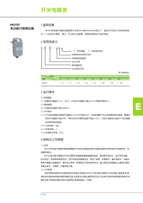
NKX101多功能行程限位器N KX 101-□/□ □“S”带传感器,“F”非标准传动比标准传动比序号(见表1)标准控制回路数设计代号限位器型号企业特征代号中。
广泛应用于建筑、港口、矿山等行业起重、传输机械空间三坐标控制。
NKX101多功能行程限位器适用于交流50Hz(或60Hz)380V及以下,直流220V及以下的控制电路表1 标准传动比 1∶131∶171∶461∶601∶781∶2101∶2741∶960NKX101 4.1 结构NKX101多功能行程限位器由高精度的大传动比减速机构和与其输出轴同步的机械记忆控制机构、传感器等组成。
NKX101多功能行程限位开关主要零件由高强度耐高温塑料制成,具有零件数目少,动作灵活可靠、快分快合、机械寿命高等特点。
它的外壳采用增强尼龙,保证了强度、抗震要求;触头系统中,动触头具有与静触头接触良好,零件加工简单,容易保证产品性能的特点。
触头系统采用铜触头与银氧化隔合金触头配对,抗熔焊、抗磨损能力强。
4.2 工作原理与被控制机构同步的位移信号经外接挂轮变速后与NKX101多功能行程限位开关的输入轴联接,经减速机构变速转换成输出轴的角度位移,从而驱动与输出轴同步的记忆凸轮使与控制电路连接的微动开关瞬时切换,实现被控制机构的行程控制以及极限限位。
(见图1)4 结构与工作原理1 适用范围2 型号及含义3 运行条件输入轴传感器记忆凸轮微动开关控制电路减速机构位移信号5.1 额定工作电压:AC380V DC220V5.2 额定工作电流:AC0.79A DC0.14A5.3 重复定位精度:记忆凸轮的转角误差不大于0.005rad5.4 控制回路数:标准控制回路数为1~4个,根据客户要求可以增到6个5.5 最大有效转角:320°6.1 开关外形及安装尺寸见图二。
大汉塔机QTZ80(6010)说明书
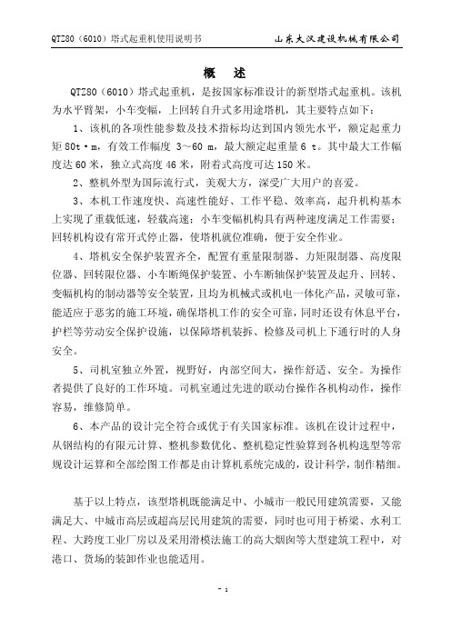
概 述QTZ80(6010)塔式起重机,是按国家标准设计的新型塔式起重机。
该机为水平臂架,小车变幅,上回转自升式多用途塔机,其主要特点如下:1、该机的各项性能参数及技术指标均达到国内领先水平,额定起重力矩80t·m,有效工作幅度 3~60 m,最大额定起重量6 t。
其中最大工作幅度达60米,独立式高度46米,附着式高度可达150米。
2、整机外型为国际流行式,美观大方,深受广大用户的喜爱。
3、本机工作速度快、高速性能好、工作平稳、效率高,起升机构基本上实现了重载低速,轻载高速;小车变幅机构具有两种速度满足工作需要;回转机构设有常开式停止器,使塔机就位准确,便于安全作业。
4、塔机安全保护装置齐全,配置有重量限制器、力矩限制器、高度限位器、回转限位器、小车断绳保护装置、小车断轴保护装置及起升、回转、变幅机构的制动器等安全装置,且均为机械式或机电一体化产品,灵敏可靠,能适应于恶劣的施工环境,确保塔机工作的安全可靠,同时还设有休息平台,护栏等劳动安全保护设施,以保障塔机装拆、检修及司机上下通行时的人身安全。
5、司机室独立外置,视野好,内部空间大,操作舒适、安全。
为操作者提供了良好的工作环境。
司机室通过先进的联动台操作各机构动作,操作容易,维修简单。
6、本产品的设计完全符合或优于有关国家标准。
该机在设计过程中,从钢结构的有限元计算、整机参数优化、整机稳定性验算到各机构选型等常规设计运算和全部绘图工作都是由计算机系统完成的,设计科学,制作精细。
基于以上特点,该型塔机既能满足中、小城市一般民用建筑需要,又能满足大、中城市高层或超高层民用建筑的需要,同时也可用于桥梁、水利工程、大跨度工业厂房以及采用滑模法施工的高大烟囱等大型建筑工程中,对港口、货场的装卸作业也能适用。
1.整机外形尺寸及技术性能1.1整机外形尺寸1.1.1独立式1.1.2附着式1.2起重特性 1.2.1起重特性表60米起重性能表幅 度(m ) 3~11 12 14 16 18 20 22 24 26 28 30 32 34 二倍 率 30002850 2620 24202240吊重kg四 倍 率 6000 5440476042203780341031002830 2600 23902210幅 度(m )36 38 40 42 44 46 48 50 52 54 56 58 60 二 倍 率 2080 1940 1810 1690159014901400132012501180 1110 10501000吊 重 kg四 倍 率2050 1910 1780 1670156014601380129012201150 1090 103097055米起重性能表50米起重性能表起重力矩曲线图1.3整机技术性能起重机技术参数表利用等U5 安装、拆卸、顶升或降节时最大安装高度处的风级≤4级 载荷状Q2 工作状态风级 ≤6级 工作级A5非工作状态风级 ≤11级参数名称单位 设计值 额定起重力矩 t.m 80 最大额定起重量 t 6 工作幅度m 3-60 最大幅度处额定起重量 t 1.0 独立式 m 46 二倍率m 150 高 度附着式 四倍率 m 75倍 率/ α=2α=4速 度 m/min 8.540 80 4.25 20 40起升速度相应最大起重量 t 331.5663电机型号 / YZTD225L 2-4/8/32功率kW 24/24/5.4 起升机构 转速 r/min 1383/699/141回转速度 r/min 0.6 电机型号 / YZR132M 2-6 功率 kW 2×3.7 回转机构 转速 r/min 908 变幅速度 m/min 48/24 电机型号 / YDEZ132S-4/8 功率 kW 2.2/3.3 变幅机构转速 r/min 1390/710 顶升速度m/min 0.55 液压系统额定工作压力 MPa 25 电机型号 / Y132M-4 功率kW 5.5 顶 升 机构 转速 r/min 1440 尾部回转半径 m 12.96 平衡重t 14.7 整机自重(不含平衡重) t 36.02 总功率kW40.21.4主要外购件及其技术指标型号/ YZTD225L 2-4/8/32功率 kW 24/24/5.4 电动机转速 r/min 1383/699/141 型号 / YWZ 3-315/45 制动器 制动力矩 N·m315-630 型号 / QTJ63 减速机速比/ i=15.07 钢丝绳/ φ132倍率 4倍率起升速度 m/min 8.540 80 4.25 2040 起 升 机 构 最大起重量t331.5663型号/ YZR132M 2-6 功率 KW 2×3.7 电动机 转速r/min 908 制动器/内置 回 转机 构 行星齿轮减速机减速比 / i=180型号/ YDEZ132S-4/8 功率 KW 2.2/3.3 电动机 转速r/min 1390/710 减速机 / 行星齿轮减速机变 幅 机 构 钢丝绳/φ7.7 型号/ Y132M-4 功率 kW 5.5 电动机转速r/min 1440 流量 L/min 10 液压泵站额定压力 MPa 25 液压油缸 型号/ HSGK-160/110E顶升机构行程mm16002.塔机主要构造及特点2.1总体布置2.1.1独立式独立高度46米,可采用二倍率或四倍率钢丝绳起升,塔身下部通过预埋支腿或井字架与基础相连,上部通过回转总成(下支座、回转支承、上支座)与回转塔身相连,司机室侧置于上支座,前方是吊臂,后方是平衡臂,起升机构设在平衡臂尾部,回转机构对称置于上转台侧边,变幅小车由变幅机构牵引,沿臂架来回作水平运动,起重臂、平衡臂均用刚性拉杆与塔帽连接。
MAXSTI STI 智能定位器 FT 系列 说明书

P081968 2008 年制造
为了使设备处于安全的环境下,并确保其安全运行,请仔细阅读并遵守各章节中各自符号标志的说 明。
当无法保证安全运行的情况下,必须关闭设备并确保已受到可靠的保护以避免无意的重新启动。无 法保证安全运行的原因可能是:
配件 1 供应/输出仪表 2 用供应/输出仪表的锁定装置 3 特制的
大连万讯电力仪表有限公司 TEL:0411-39759181 FAX:0411-39759180 WEB:
1.3 制造商标牌
FT为每一台远程定位器命名: 并镀上了其序列号。 序列号的前两位表示制造日期 (*).
2.6 气动安全
•遵守H&S组织的事故预防规则。 •遵守所使用的气动执行器的安全指示。
注意
•采取适当的预防措施,以确保即使在出现故障的情况下也没有超过远程定位器的最大允许工作压 力。否则,远程定位器和/或执行器可能被损坏。
•给远程定位器提供的仪表空气必须是无油、无水和无灰尘的,并且根据ISO 8573-1可达到3级。 纯度:最大微粒粒径5µm,最大粒子密度5mg/m3 油含量:最大浓度1mg/m3 压力露点:在工作温度下最高值10K。 当将液体而非空气用于此产品,并应用于其他非工业用途时,必须先咨询STI。
警告 •不要使用易燃气体,氧气或含氧量高气体作为气压介质。 •使用的电缆和接线口的工作温度要分别比最高允许的工作温度高10K,比最低允许的工作温
度低10K。
大连万讯电力仪表有限公司 TEL:0411-39759181 FAX:0411-39759180 WEB:
• 输入 模拟:可配置分程的 4-20 mA – Hart 协议。 开关:2 进制数字量输入(光耦合器 24VDC )。
APL系列限位开关说明书

L I M I T S W I T C H E S1APL 2 SeriesCSA Approved, Type 4XValve Position MonitorsAPL 5 SeriesCSA Approved Type 4X/6Class I, Div 1, Grps B, C, D T6Class II, Div 1, Grps E, F , G Class IIICUSNEW:APL-9 Series Stainless Steel Type 4X, IP 67T riac ®APL Series Limit Switches The Triac APL Series Limit Switches feature high quality, easy to use multiple option switch boxes for rotary actuators. Their die cast aluminum housings are powder coated for corrosion resistance and feature red/ green visual indicators, quick-set cams and easy access terminal strips. These economical switch boxes offer numerous switch, sensor and transmitter options to handle most applications found in today’s process• Solid and compact design• Dome visual indicator (3-way available)• Dual 1/2” NPT conduit entries, 8 pts. on terminal strip • Quick-set spring loaded cam• Captive cover bolts• NAMUR low profile brackets• Available Switches 10, 18, 20 & 23• Ambient temperature range -20°C to 80°C (-4°F to 176°F)APL-210APL-218Simple device for intrinsicallysafe applicationsC US262375NEW: APL-9 Series Stainless SteelType 4X, IP 67304 Stainless Steel enclosureStainless Steel shaft & captive cover boltsDome visual indicatorDual 1/2” NPT conduit entries, 8 pts. on terminal stripQuick-set spring loaded camNAMUR stainless steel bracketMultiple options - up to four switches, intrinsically safe,reed type sensors (See options 12, 20, and 30 on page 7)Ambient temperature range -20°C to 80°C (-4°F to 176°F)2L I M I T S W I T C H E S3APL-3 SeriesAPL-4 SeriesAPL-5 Series• CSA Approved, Type 4X• Die-cast aluminum powder coated enclosure• Rugged and flexible design• Dome visual indicator (3-way available)• Dual 1/2” NPT conduit entries, 8 pts. on terminal strip • Quick-set spring loaded cam • Captive cover bolts • NAMUR brackets• Multiple options - up to four switches, various mechanical, proximity and reed type sensors, feedback potentiometers and 4-20mA transmittersAmbient temperature range -20°C to 80°C (-4°F to 176°F)CSA Approved, Class I, Division 1, Groups C & D T6 Class I, Zone 1, AEx d IIB, T6, Ex d IIB, T6, Type 4X/6, IP 66/67/68ATEX/IECEx rating available: Ex d IIB T6 Gb(*Use ATEX suffix to denote this option. Ex: APL-410N-ATEX)• Dome visual indicator (3-way available)• Dual 3/4” NPT conduit entries, 8 pts. on terminal strip Quick-set spring loaded cam Captive cover bolts NAMUR bracketsMultiple options - up to four switches, various mechanical, proximity and reed type sensors, feedback potentiometers and 4-20mA transmittersAmbient temperature range -20°C to 60°C (-4°F to 140°F)•CSA Approved: Type 4X/6, IP 66/67Class I, Division 1, Group B, C & D T6; Class II, Division 1, Group E, F, G; Class III Class I, Zone 1, AEx d IIC, T6;Class II, Zone 21, AEx tb IIIC T65°C DbEx d IIC, T6; Ex tb T65°C DbATEX/IECEx rating available:Ex d IIC T6 Gb; Ex tb IIIC T85°C Db, IP67(*Use ATEX suffix to denote this option. Ex: APL-510N-ATEX)Dome visual indicator (3-way available)Dual 3/4” NPT conduit entries, 8 pts. on terminal strip Quick-set spring loaded camScrew on enclosure lid with spring loaded cover bolts - unique design to hold bolts inside cover NAMUR bracketsproximity and reed type sensors, feedback potentiometers and 4-20mA transmitters• Ambient temperature range -20°C to 60°C (-4°F to 140°F)•Low temp option down to -50°C (-58°F) with C1, C3 switches onlyC US 262375C US 262375CUS2623754APL-2 SeriesAPL-3 SeriesAPL-4 SeriesAPL-5 SeriesL I M I T S W I T C H E S5(2) DPDT SWITCHES(2) SPDT SWITCHES 5K OHM POTENTIOMETER(2) SPDT SWITCHES 4-20mA TRANSMITTER (2) P&F NJ2-V3-N SOLID STATE SENSORS12GROUND5349786121110RED BLACK NCWHITE BROWN YELLOW C BLUE RED BLACK NONC CNC NO WHITE BROWN NOC NCNOYELLOW TOP SWITCHSWITCHBOTTOM CBLUE OPENCLOSE 13EXT14VALVESOLENOID 3CLOSE12BLUE YELLOW RED BLACK NC NO COPEN56798WHITE BROWNCNO123GROUNDNC 4TOP SWITCHSWITCHBOTTOM POTENTIOMETER111210VALVESOLENOID EXTR-I CONVERTERGROUND12VALVESOLENOID CCNONONC 321SWITCHBOTTOM POTENTIOMETER-+1CLOSE RED BLACK BLUE OPENBROWNWHITE YELLOW NCSWITCHTOP 658971110342+-BROWNBLUESWITCH MODEL:NJ2-V3-N-V5TYPE:PROXIMITY SWITCHS VOLTAGE: 5V--30V DCNOTEGROUNDWiring Schematics(2) SPDT SWITCHESNCNO CBOTTOM SWITCHGREENNOREDNCTOP SWITCHCLOSE BLACK OPEN BROWNGROUND7EXT86YELLOW BLUE WHITE C5423VALVESOLENOID RED 1(4) SPDT SWITCHES12GROUND5349786121110RED BLACK NCWHITE BROWN YELLOW C BLUE RED BLACK NONC CNC NOWHITE BROWN NOCNC NO YELLOW CBLUE BOTTOM SWITCHGREENREDGREENREDTOP SWITCHCLOSEOPEN CLOSE OPEN 13EXT14VALVESOLENOIDSolenoid Valve Integration:APL-5 Series & ASCO Solenoid3-Way Solenoid+EF8320G184+EV8320G202+EV8316G381V-D244-Way Solenoid+EF8342G001+EV8342G701Triac Cobra Limit Switches:The Triac Cobra hermetically sealed proximity switcheshave a patent pending design for high (C1) and low(C3) current applications. This design has the currentcapability of a mechanical switch with the reliability ofsolid state sensors with up to 10,000,000 cycles.We recommend using our Cobra C3 (Gold Bifurcated)limit switch for low current and intrinsically safeapplications.C1 HermeticallySealed Proximity Switch Silver Oxide SPDT Contacts Contact Rating5 A resistive, 3 A inductive, 28VDC 5 A resistive or inductive. 250VAC C3 HermeticallySealed Proximity SwitchGold Bifurcated SPDT Contacts Contact Rating1 A resistive, 0.5 A inductive, 28VDC 1 A resistive or inductive. 125VACNOTES: • entry must be closed with appropriate conduit plug.†is required during installation.8TriacEX Series Limit Switches The TriacEX Series hazardous location Limit Switch provides a compact design and low cost for both visual and remote electrical indication of rotary valve/actuator position. The heavy duty design and wide variety of options make the EX Series the ideal multi-purpose Limit Switch for use in NEMA 4, 4X, 7 and 9 applications.Features:• Aluminum Housing: Polyester Powder Coating• Twin Shaft Body Design: The primary shaft is located in the housing base and connects to a mating shaft located in the housing cover. This twin shaft feature allows easy and accurate housingassembly by eliminating the blind-hole configuration associated with competitive switch boxes.• Multiple Switch Options: Wide variety of mechanical, proximity and inductive switch options provide the most effective andeconomical choice for each specific application.• Visual Position Indication: The 3D rotor provides high visibility confirmation of valve/actuator position. The splined retainer allows adjustment to coincide with the exact valve position.• “Easy-Set” Cams: Splined, spring loaded and independently adjustable. This design offers tool-free calibration and positivevibration resistant engagement.• Multiple Cable Entries: Standard with two ½” NPT cable entries with option for third ½” or ¾” NPT cable entry.• Standardized Mounting: ISO F05 mounting pattern and VDI/ VDE3845 shaft• Options: AS-i digital communication interface card, 3-position dribble control, 4-20mA feedback transmitter, special terminal strips,NAMUR mounting brackets.L I MIT S W I T C H E S9Triac : UL Listed and Explosion Proof Limit Switches• Available in Aluminum (EC) or 316SST (ES)Housing• UL Listed NEMA 4, 4X, Weather Proof • Visual indicator options• Dual threaded conduit entries with extra terminals • High Resolution Splined Cam• Temperature Range: -40˚F (-40˚C) to 176˚F (80˚C)• ISO F05 mounting pattern and VDI/VDE3845 shaft Available with 3-way Pneumatic valveMultiple options - up to three switches, variousmechanical, proximity and reed type sensors,feedback potentiometers and 4-20mA transmitters, AS-i interface• Low Copper Aluminum Housing• UL Listed NEMA 4, 4X, 7 & 9, Explosion Proof & Weather ProofClass I, Division 1, Groups B, C & D Class II, Division 1, Groups E, F & G • Visual indicator with twin shaft design• Up to four conduit entries with extra terminal options • High Resolution Splined Cam• Temperature Range: -40˚F (-40˚C) to 176˚F (80˚C) (T6)• Low Temperature rating down to -76˚F (-60˚C) available onrequest (available with 1D Switch option only)• ISO F05 mounting pattern and VDI/VDE3845 shaft• Multiple options - up to six switches, various mechanical,proximity and reed type sensors, feedback potentiometers and 4-20mA transmitters• 316 Stainless Steel Housing• UL Listed NEMA 4, 4X, 7 & 9, Explosion Proof & Weather ProofClass I, Division 1, Groups B, C & D Class II, Division 1, Groups E, F & G• Visual indicator options with twin shaft design• Up to four conduit entries with extra terminal options • High Resolution Splined Cam• Temperature Range: -40˚F (-40˚C) to 176˚F (80˚C) (T6)• request (available with 1D Switch option only)• ISO F05 mounting pattern and VDI/VDE3845 shaft • Multiple options - up to six switches, variousmechanical, proximity and reed type sensors, feedback potentiometers and 4-20mA transmittersEY SeriesEW SeriesEC/ES Series10How To OrderUL Listed and Explosion Proof Limit SwitchesNOTES:*Gold plated switches are suitable for intrinsically safe applictions and also hazardous locations.*Conduit plugs supplied with the switch box are for transit purposes only. To ensure Type 4, 4X, 7 & 9 protection, any unused conduit entry must be closed with appropriate conduit plug.NOTE #1:EX series has the following approval:• Enclosure Approvals: UL and cUL, Type 4, 4X, 7 & 9, (ML FILE NO. E236166)• Class I, Division 1 Groups C & D • Class II, Division 1, Groups E, F & G NOTE #2:EY & EW series have the following approval:• Enclosure Approvals: UL and cUL, Type 4, 4X, 7 & 9, (ML FILE NO. E236166)• Class I, Division 1 Groups B, C, & D • Class II, Division 1, Groups E, F & G NOTE #3:EC, ES, EX, EY & EW series have the following approvals:• Enclosure Approvals: UL and cUL, Type 4, 4X, (ML FILE NO. E336774)• Switch Approvals: UL and cUL (ML FILE NO. E236166) (Proximity Reed and Solid State Sensors only)• Class I, Division 2, Groups A, B, C & D • Class II, Division 2, Groups F & G NOTE #4:The recommended minimum load for switch type “0A”, “0E”, & “N1” is 50mA. All other switch types are suitable for applica-tions as low as 1mA.NOTE #5:EW enclosure with 1D switch is the only combination rated to low temp applications (-76°F/-60°C).EX 1 0A 2 S BK N-20Series IndicationSwitch Type Switch Quantity Mounting BracketLimitSwitches-20190823Copyright 2013 A-T Controls, Inc.LIT00229955 International Blvd.Cincinnati, Ohio PHONE (513) 247-5465FAX (513) 247-5462********************。
多功能行程限位器选型标准

多功能行程限位器选型标准
多功能行程限位器的选型标准主要包括以下几个方面:
1. 限位器的类型:根据实际需求选择常开型、常闭型、一开闭型等。
2. 额定电流和电压:根据实际使用环境和设备,选择符合要求的电流和电压范围。
3. 应用环境:根据现场环境,如温度、湿度、腐蚀、特殊气体等,选择耐高温、耐低温、耐水、耐油、防腐蚀、防爆等适合的限位器。
4. 产品的动作模式:根据实际需求选择摇杆式、柱塞式、万能式等。
5. 尺寸:根据机械设备的类型和结构,以及限位器本身的尺寸和性能,选择合适的限位器尺寸。
同时需要考虑工作环境的温度、湿度等因素。
6. 材料:根据工作环境的条件选择合适的材料,以保障限位器的性能和使用寿命。
7. 灵敏度:选择高灵敏度或常规灵敏度的限位器,以满足对精度和安全性的要求。
8. 其他特性:如是否需要带公共端子、普通端子等,也需要根据实际需求进行选择。
总之,在选择多功能行程限位器时,需要根据实际需求和应用环境进行综合考虑,选择适合的类型、规格和性能参数,以确保机械设备的安全性和运行精度。
DXZ系列行程限位器
选用机械行程限位器时,最重要的指标就是传动比, 由于机械原件在加工上不可避免的存在一定误差,因此,为了保证客户的使用精度, 选择合适的传动比就显得尤为重量, 如何选择呢? 基本原则是, 卷扬工作的全过程应该小于行程限位器中记忆突轮转动的一周. 例如: 卷扬工作全过程需要转动10圈, 也就是输入轴转动10圈, 行程限位器内部的突轮最多只能转一圈, 根据选型手册, 我们可以选择传动比为1:13的, 但如果卷扬工作全过程中转动了4圈, 而依旧选传动比为1:13的行程限位器, 那么在实际使用中会产生较大的控制误差, 因此, 应选择与实际转动相接近的传动比.
DXZ系列行程限位器是一种机械式行程限位器, 因此具有体积小、结构紧凑、抗扰、 限位可调、通用性强、安装和维护方便等特点。
其结构主要是由: 变速齿轮, 记忆突轮以及微动开关等几部分主成, 具体工作如下: 将行程限位器安装在与卷扬同轴的位置, 通过输入轴,将卷扬的转速同步输入到行程限位器内部的变速齿轮上, 通过变速齿轮的不同传动比, 可以带动记忆突轮的旋转, 每当记忆突轮到达设定的位置时,会顶起微动开关的触点, 将原常闭触点断开,从而达到机械限位的功能.
/dgnxcxwq
限位开关产品说明书

91 Flexible rod steel
Iso 20 1/2" NPT
Type
Order code
LS43M11B11 1SBV011611R1211
LS45M11B11 1SBV013111R1211
LS43M13B11 1SBV011613R1211
LS45M13B11 1SBV013113R1211
Head type
Cable inlet
11 Plain plunger steel
Iso 20 1/2" NPT
13 Roller plunger steel
Iso 20 1/2" NPT
41 Roller lever plastic
Iso 20 1/2" NPT
51 Adjustable Iso 20 roller lever plastic 1/2" NPT
LS33M51B11 1SBV013851R1211
LS35M51B11 1SBV013751R1211
LS32M91B11 1SBV011991R1211
LS33M91B11 1SBV013891R1211
LS35M91B11 1SBV013791R1211
Width 40 mm
Plastic casing - Double insulation - IP65
1SBC141159L0201_Printed version (07.2016 PDF) Copyright© 2016 ABB - All rights reserved.
A simple core range selection covering 80% of the applications…
H 310 - 行程计数器说明书
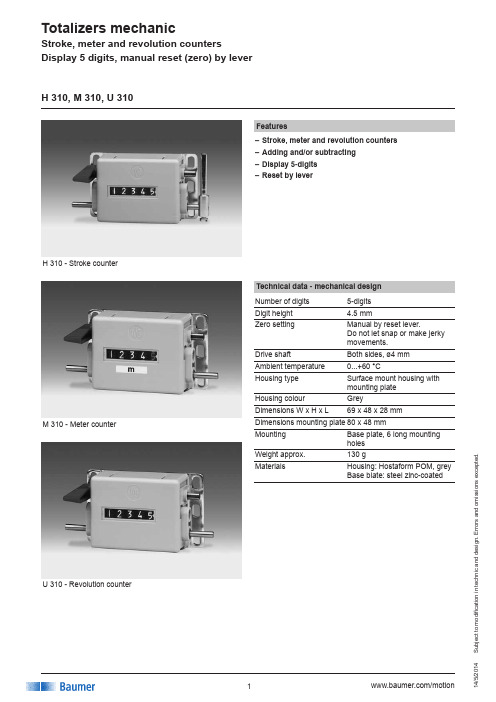
u b j e c t t o m o d i fi c a t i o n i n t e c h n i c a n d d e s i g n . E r r o r s a n d o m i s s i o n s e x c e p t e d .H 310 - Stroke counterFeatures–Stroke, meter and revolution counters –Adding and/or subtracting –Display 5-digits –Reset by leverH 310, M 310, U 310Technical data - mechanical design Number of digits 5-digits Digit height 4.5 mmZero settingManual by reset lever.Do not let snap or make jerky movements.Drive shaftBoth sides, ø4 mm Ambient temperature 0...+60 °CHousing type Surface mount housing with mounting plate Housing colour GreyDimensions W x H x L69 x 48 x 28 mmDimensions mounting plate 80 x 48 mmMounting Base plate, 6 long mounting holesWeight approx.130 gMaterialsHousing: Hostaform POM, grey Base blate: steel zinc-coatedM 310 - Meter counterU 310 - Revolution counteru b j e c t t o m o d i fi c a t i o n i n t e c h n i c a n d d e s i g n . E r r o r s a n d o m i s s i o n s e x c e p t e d .H 310, M 310, U 310Away from userToward userSense of rotation or Sense of rotation or stroke direction I stroke direction IIDirection of strokes and rotation Technical data - mechanical design H 310Function Stroke counterDisplay White numbers on black Count mode Adding in a stroke direction to be indicated. 1 stroke = 1 count Stroke >38° to <60°Stroke leverTo be positioned on shaft at will. Stroke lever relocatesautomatically to start position.Stroke frequency ≤500 strokes/min Measuring range 99 999M 310Function Meter counterDisplay White numbers on black Decimal digits in redCount modeAdding in a rotational direction to be indicated, subtractingin reverse direction. 5 revs. = 10 countsMeasuring speed <200 m/min (measuring wheel)Measuring accuracy 1 dm Measuring range 9999.9 mU 310Function Revolution counter Display White numbers on black Count modeAdding in a rotational direction to be indicated, subtracting in reverse direction. 1 rev. = 1 count Operating speed ≤3000 rpm Measuring range99 999AccessoriesMeasuring wheels for M 310MR211.04A Circumf. 20 cm, knurled aluminium MR241.04D Circumf. 20 cm, smooth Hytrel TPE-E MR261.04A Circumf. 20 cm, knopped rubber NBR Nitril MR291.04D Circumf. 20 cm, grooved Hytrel TPE-Eu b j e c t t o m o d i fi c a t i o n i n t e c h n i c a n d d e s i g n . E r r o r s a n d o m i s s i o n s e x c e p t e d .H 310, M 310, U 310Part number H 310.010A01Display / direction of stroke A 5 digits 99 999 / I B 5 digits 99 999 / IICount mode / drive011 stroke = 1 digit / drive shaft onboth sidesHousingA Surface mount housing, greyZero setting010With reset lever M 310.010A06Display / direction of rotation C 5 digits 9999.9 / I D 5 digits 9999.9 / IICount mode / drive06 5 revolutions = 10 digits =1.0 m / drive shaft on both sidesHousingA Surface mount housing, greyZero setting010With reset leverU 310.010A01Display / direction of rotation A 5 digits 99 999 / I B 5 digits 99 999 / IICount mode / drive011 revolution = 1 digit / drive shaft onboth sidesHousingA Surface mount housing, greyZero setting010With reset leverStroke counter Meter counterRevolution counteru b j e c t t o m o d i fi c a t i o n i n t e c h n i c a n d d e s i g n . E r r o r s a n d o m i s s i o n s e x c e p t e d .DimensionsH 310, M 310, U 310。
- 1、下载文档前请自行甄别文档内容的完整性,平台不提供额外的编辑、内容补充、找答案等附加服务。
- 2、"仅部分预览"的文档,不可在线预览部分如存在完整性等问题,可反馈申请退款(可完整预览的文档不适用该条件!)。
- 3、如文档侵犯您的权益,请联系客服反馈,我们会尽快为您处理(人工客服工作时间:9:00-18:30)。
正天科技
DXZ型多功能行程限位器使用说明书
徐州正天科技有限公司
一、概述
DXZ型多功能行程限位器(简称限位器)系引进法国波坦茵(POTAIN)公司产品国产化设计生产。
DXZ型多功能行程限位器的各性能指标均达法国波坦茵(POTAIN)公司产品技术要求。
1.1 DXZ型多功能行程限位器用途及适用范围
DXZ型多功能行程限位器可广泛应用于建筑、港口、矿山等行业的起重、传输机械的空间三坐标的控制和限位,DXZ型多功能行程限位器具有体积小、功能多、精度高、限位可调、通用性强及维护安装和使用调整方便等特点。
1.2 DXZ型多功能行程限位器的主要技术参数
a、DXZ型多功能行程限位器工作环境
环境温度:233-328K (-40-- +55℃)
相对湿度:不大于90%
b、DXZ型多功能行程限位器
传动比:1:13-----1:960
c、DXZ型多功能行程限位器重复定位精度:
记忆凸轮的转角误差不大于0.005rad
d、DXZ型多功能行程限位器额定电压:
AC:125—250V
DC:30V
e、DXZ型多功能行程限位器额定电流:6A
f、DXZ型多功能行程限位器控制回路
标准设计回路为1—4个,可根据用户需要增至5-6个控制回路
2、DXZ型多功能行程限位器结构和工作原理
2.1 DXZ型多功能行程限位器结构
DXZ型多功能行程限位器由高精度的大传动比减速器和与其输出轴同步的机械记忆控制机构、传感器组成。
2.2 DXZ型多功能行程限位器工作原理
2.2.1 DXZ型多功能行程限位器与被控制机构同步的位移信号经外接挂轮变速后与限位器的输入轴联接,经减速器变速转换成输出轴的角位移信号而实现。
3、DXZ型多功能行程限位器安装和调整
DXZ型多功能行程限位器调整轴对应的记忆凸轮及微动开关分别为:1Z—1T—1WK;
2Z—2T—2WK;
3Z—3T—3WK;
4Z—4T—4WK;
DXZ型多功能行程限位器调整程序
a、拆开上罩壳,检查并拧紧2—M3×55螺钉。
b、松开M5螺母。
c、根据需要,将被控机构开至指定位置(空载),这时控制该机构动作对应的微动开关应瞬时切换。
即:调整对应的调整轴(Z)使记忆凸轮(T)压下微动开关(WK)触点。
d、拧紧M5螺母。
(螺母一定要拧紧,否则将产生记忆紊乱)。
e、机构应反复空载运行数次,验证记忆位置是否准确。
(有误时重复上述调整)。
f、确认位置符合要求;紧固M5螺母、装上罩壳。
g、机构正常工作后,应经常核对记忆控制位置是否变动,以便及时修正。
3、用户订货须知
3.1型号的功能
用户根据需要,按以下范例准确提出产品的规格和数量。
标准传动比序号见下表:
例1:DXZ-4/7
即:限位的控制回路数为4个,传动比为1:274。
例2:DXZ-6/F
即:限位的控制回路数为6个,非标;传动比为1:600。
限位器型号。