苏民峰 峰生水起 精读卡全 高清
1-s2.0-S0264127516312965-main
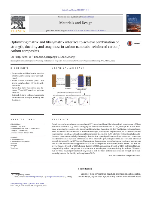
Optimizing matrix and fiber/matrix interface to achieve combination of strength,ductility and toughness in carbon nanotube-reinforced carbon/carbon compositesLei Feng,Kezhi Li ⁎,Bei Xue,Qiangang Fu,Leilei Zhang ⁎State Key Laboratory of Solidi fication Processing,Carbon/Carbon Composites Research Center,Northwestern Polytechnical University,Xi'an,710072,ChinaH I G H L I G H T S•Both matrix and fiber/matrix interface of carbon/carbon composites were opti-mized.•Radial carbon nanotube (CNT)was grown on carbon fibers (CF)to strength-en matrix.•Pyrocarbon layer was introduced be-tween CF and CNT/matrix to optimize interface.•Optimal designs endowed composite with improved strength,ductility and toughness.G R A P H I C A L A B S T R A CTa b s t r a c ta r t i c l e i n f o Article history:Received 2July 2016Received in revised form 2October 2016Accepted 3October 2016Available online 5October 2016The direct attachment of carbon nanotubes (CNTs)on carbon fibers (CFs)always leads to a decrease of fiber-dominated properties (e.g.,flexural strength)and a brittle fracture behavior of C/Cs,although the matrix-domi-nated properties (e.g.,compressive strength and interlaminar shear strength (ILSS))exhibit an obvious enhance-ment.To achieve the combination of mechanical strength,ductility and toughness in C/Cs,in this work,efforts were spent on simultaneously optimizing the matrix and fiber/matrix (F/M)Ts with radial orienta-tion were grown onto the CFs by double-injection chemical vapor deposition to modify the microstructure of ma-trix.Pyrocarbon was deposited on the surface of CFs before CNT growth to protect CFs and to weaken interfacial strength between CFs and CNT/matrix.These optimal designs create strengthening and toughness mechanisms such as crack de flection and long pullout of CFs in the failure process of composites,which endow C/Cs with im-proved flexural strength of 31.5%,flexural ductility of 118%,compressive strength of 81.5%and ILSS of 82%,ac-companied by a clear change from brittle fracture to pseudo-plastic fracture during flexural test.This work may provide a meaningful way to not only enhance both the fiber-and matrix-dominated strength but to sub-stantially improve the ductility and toughness of C/Cs.©2016Elsevier Ltd.All rights reserved.Keywords:Carbon nanotubesCarbon/carbon composites Interface Strength Toughness1.IntroductionDesign of high-performance structural engineering carbon/carbon composites (C/Cs)is driven by optimizing combinations of mechanicalMaterials and Design 113(2017)9–16⁎Corresponding authors.E-mail addresses:likezhi@ (K.Li),zhangleilei@ (L.Zhang)./10.1016/j.matdes.2016.10.0060264-1275/©2016Elsevier Ltd.All rightsreserved.Contents lists available at ScienceDirectMaterials and Designj o u r n a l h o me p a g e :ww w.e l s e v i e r.c o m /l o c a t e /m a t d e sproperties such as strength,ductility,toughness and requirements for stability and non-catastrophic failure during service[1,2].C/Cs exhibits high specific strength and modulus,however,they have weak compres-sion and interlaminar properties,lack ductility and toughness,and al-ways fail in an apparently brittle manner in unconstrained loading geometries[3–5].Recently,the huge interest in incorporating carbon nanotubes (CNTs)into structural composites have been stimulated by virtue of their extraordinary intrinsic properties,such as ultrahigh strength,ex-cellent electrical and thermal conductivities[6,7].These outstanding mechanical and physical properties,in combination with their unique 1D nanostructures with high specific surface areas,allow for efficient tailoring of both matrix microstructure andfiber/matrix(F/M)interface state[8,9].For the incorporation of CNTs into composite structures,the general trend has been focused on in situ-growth of CNTs[10–12]or attaching CNTs to the carbonfibers(CFs)[13–15].Unlike attracting CNTs which trend to lie in the plane offiber surface and thus only pro-vide one-side reinforcement to the C/Cs(just at F/M interface area), growing CNTs on the surface of CFs by catalytic chemical vapor deposi-tion(CVD)has many advantages in terms of controllability of size and orientation of CNTs,particularly a radial orientation that allows for si-multaneous reinforcements to the matrix and F/M interface[16].Excit-ing increases in matrix-dominated properties(e.g.,compressive strength and interlaminar shear strength)of C/Cs have been observed by growing CNTs onto carbonfibers[17–19].Nevertheless,there still exit some critical issues regarding the C/Cs reinforced with CVD-grown CNTs.Firstly,due to the potential damage(dissolution of metal catalysts into carbon,local oxidation and gasification)of the CFs during the growth reaction[20,21],and the difficulty of controlling the orienta-tion and uniformity of the grafted CNTs on CFs[16,22,23],the studies on the enhancements both infiber-and matrix-dominated strengths of C/ Cs have rarely been reported.Secondly and more importantly,the direct attachment of CNTs onto CF surface always result in strong F/M interfa-cial bonding and thus obstructs the crack deflection along the axis of CFs [17,23–25],which leads to the failure offiber pullout as an effective strengthening and toughening mechanism.There will be little or no property enhancement in the ductility and toughness expected in such a mode of composite failure[26,27].If CNT-reinforced C/Cs is to re-place C/Cs in industries,it is necessary to achieve the combination of global strength,ductility and toughness in C/Cs.Over the past few de-cades,however,few efforts have been spent on this issue.To improve the comprehensive mechanical performance of CNT-re-inforced C/Cs,the substantial problem and great challenge are how to moderate the F/M interfacial bonding so that it is neither too strong nor too weak and how to supply effective reinforcements to the carbon matrix without degrading thefiber strength.In this work,a thin pyrocarbon(PyC)interface layer was deposited on the surface of CFs by chemical vapor infiltration(CVI)technique to optimize the F/M in-terfacial bonding,whilst preventing the dissolution of metal catalysts into CFs occurred during the subsequent growth of CNTs.Afterwards, double-injection CVD(DICVD)technique was developed to grow radial-ly-aligned CNTs on PyC-coated CFs.The schematic of this manufacturing process is depicted in Fig.1.The hybridfiber preforms were then desifined by CVI technique to obtain thefinal CNT-reinforced C/Cs. Three-point bending,compression and interlaminar shearing tests were applied to examine the effect of these optimal designs on the me-chanical properties of C/Cs.2.Experimental2.1.Raw materialsCarbon felts(bulk density0.2g/cm3,fiber diameters6–8μm,Yixing Tianniao Co.Ltd.,China)used in this work were fabricated by alterna-tively overlapping layers of randomly oriented shortfiber bundles with needle-punching step-by-step.2.2.Deposition of PyC interface layer on CFs and the growth of CNTsCarbon felts werefirstly deposited with an interface layer of PyC by isothermal CVI technology,which was carried out at1080°C using flowing mixture of CH4(40L/h)and N2(160L/h)under the ambient pressure.The growth of CNTs in carbon felts was conducted by DICVD technique using FeSO4·6H2O as catalyst precursor.Incipient wetness technique was applied to introduce catalysts into felts using distilled water as solvent.Afterwards,they were placed in a CVD reactor and heated to750°C under Arflowing.At the growth temperature,xylene as the hydrocarbon source was injected into the reactor through a thin tube via a syringe.Ethylenediamine as the growth promoter wasfilled in another syringe and was injected separately from the same side for the xylene injection.The ratio of injection rates of xylene and ethylenediamine was8:1.The Ar/H2(2/1)gas mixture was used as the carrier gas with aflow rate of600sccm.The growth time was2h. The direct growth of CNTs in carbon felts without PyC interface layer was also performed by DICVD technique under identical growth condi-tions.The volume fractions of CNTs in carbon felts with and without PyC interface layer were approximately1.3%.posite preparation and mechanical property testsThe densification was carried out by isothermal CVI technique for 150h under the conditions described in section2.2.The C/Cs containing both the PyC interface layer and CNTs were denoted as CNT-PyC-C/Cs, while the C/Cs containing only CNTs were denoted as CNT-C/Cs.The Fig.1.Schematic of depositing PyC interface layer on CFs and followed by growth of radial CNTs by DICVD to maintainfiber strength,optimize F/M interface and strengthen matrix of C/Cs. 10L.Feng et al./Materials and Design113(2017)9–16densities of pure C/Cs,CNT-C/Cs and CNT-PyC-C/Cs were measured in the range of 1.64–1.67g/cm 3.The sizes of samples for bending tests were machined into 50mm ×8mm ×4mm.The support span for bend-ing tests was 40mm.To study the quasi-ductile fracture behavior of the composites,a ductility factor was introduced.It was calculated from the ratio of the secant modulus (the slope of the line from the origin to the stress at failure in the flexural stress-strain curve)to the elastic modulus [28].The samples used for compression test and interlaminar shearing test were machined into the sizes of 5mm ×5mm ×4mm.The numbers of samples for bending,compression and shearing tests were not less than 5.All the tests were carried out on a universal testing machine (CMT5304)at a constant speed of 0.5mm/min.2.4.CharacterizationThe morphologies and microstructures of grafted CNTs were exam-ined by scanning electrical microscopy (SEM,JSM-6700)operated at 15kV and transmission electrical microscopy (TEM,Tecnai F30G 2)op-erated at 200kV,respectively.Microstructure of the matrix PyC was in-vestigated using polarized light microscopy (PLM,Leica DMLP).The Raman spectrum was recorded on a Renishaw Invia RM200using aninVia micro-Raman spectrometer with an Ar ion laser of 514.5nm wavelength at room temperature.3.Results and discussion3.1.Radially-aligned CNTs grafted on CFs with and without PyC coating Fig.2a shows the surface SEM image of the CFs coated with a homog-enous PyC interface layer with a thickness of about 200nm (Fig.2b).After the growth process by DICVD,the CFs without (Fig.2c)and with (Fig.2d)PyC interface layer are uniformly covered with CNTs.The CNTs exhibit radial grafting morphologies,indicating that the DICVD technique has good repeatability for growing radial CNTs on different carbonaceous substrates.These radial nanotubes extend into the space among fibers capability of providing ef ficient reinforcements both to the interlaminar and intralaminar matrix [29].Observation of the cross-section of hybrid fibers presents the detailed information about the CNT length ranging from 4to 7μm (Fig.2e).TEM investigation (Fig.2f)reveals that the products are hollow nanotubes with smooth walls and a typical outer diameter of about 300nm.And the inner diam-eter and tube-wall thickness are about 200nm and 50nm,respectively.Fig.2.SEM images:(a)surface and (b)cross-section of PyC-coated CFs;(c)surface of radially-aligned CNTs grafted on CFs;(d)surface and (e)cross-section of radially-aligned CNTs grafted on PyC-coated CFs.(f)TEM image of an individual CNT and its high resolution TEM image (inset of f).11L.Feng et al./Materials and Design 113(2017)9–16High resolution TEM image (Fig.2f inset)presents that the CNTs have multi-walled structures and the graphitic sheets are parallel to the axial direction,exhibiting a good crystallinity.3.2.Microstructure of compositesThe polished transverse section of the C/Cs,CNT-C/Cs and CNT-PyC-C/Cs viewed by polarized light microscopy is shown in Fig.3.For C/Cs (Fig.3a),the PyC around CFs is in the shape of circular shell and has large grain size,long boundaries between interference colors and pro-nounced homocentric annular cracks.By contrast,PyC in CNT-PyC-C/Cs (Fig.3b)and CNT-C/Cs (Fig.3b inset)demonstrates a different mor-phology.As for the CFs grafted with radial CNTs,the PyC will deposit around the nanotubes rather than directly on the surface of CFs (here,CNTs provide direct reinforcement to the matrix within the reach of nanotubes).Besides,it has been demonstrated in our previous work [30],where the CNTs can also affect the PyC out of the reach of nano-tubes by inducing the formation of spherical or cone-shaped PyC and then restricting their growing up (here,it can be called as “indirect rein-forcement ”).As a result,the consequent PyC is clearly different in mor-phology from that in pure C/Cs.As seen,the PyC in C/Cs containing CNTs exhibits small grain size,short boundaries between interference colors and no annular cracks.In addition,it is interesting to note that CFs in CNT-PyC-C/Cs present white outlines (labeled by arrows in Fig.3b)at-tributed to the presence of PyC interface layers.Fig.3c and d presents the Raman results of C/Cs and CNT-PyC-C/Cs (same with CNT-C/Cs),respectively.Intensity ratio of disorder-inducedD-peak and tangential G-peak is inversely proportional to the level of crystalline order and crystal size L a (in nm)[31].As stated in Table 1,the D:G intensity ratio,I D /I G ,is about 1.85for C/Cs and falls to approxi-mately 1.52for CNT-PyC-C/Cs,suggesting that PyC has a signi ficant im-provement in crystallinity and meanwhile a big increase in L a after introducing radial CNTs.Axisymmetric peak broadening represents for large interplanar spacing d 002of carbon materials [32].As seen,both G-peak and D-peak of interlayer become sharper and more de fined after introducing radial CNTs,which indicates that,the d 002value of PyC in CNT-PyC-C/Cs has a distinct decrease compared with that in C/Cs.As the crystalline order improves and crystal size increases,the bond density within the interlayer increases [33].High bond densities and few defects could lead to a signi ficant increase in mechanical strength of PyC matrix.3.3.Mechanical properties of compositesFig.4presents the stress-strain curves of the three composites re-corded during bending test,compression test and shearing test.The de-tailed results of mechanical tests of three composites are listed in Table pared with C/Cs,CNT-PyC-C/Cs shows obvious improve-ment in flexural strength,flexural ductility,compressive strength and interlaminar shear strength (ILSS):31.5%in flexural strength,118%in flexural ductility,81.5%in compressive strength and 82%in ILSS.How-ever,the flexural strength and flexural ductility of CNT-C/Cs are de-creased by 14.5%and 73%,although the compressive strength and ILSS are increased by 67%and 115%,respectively.From the flexuralstress-Fig.3.PLM images (a,b and inset)and Raman spectra (c,d)of the three composites:(a and c)C/Cs;(inset of b)CNT-C/Cs;(b and d)CNT-PyC-C/Cs (note:red points marked in a and b are the Raman detection positions).Table 1Raman testing data of C/Cs,and CNT-PyC-C/Cs (±values represent standard deviation).Composite FWHM of G-peak (cm −1)FWHM of D-peak (cm −1)I D /I GC/Cs84.41±0.21116.54±0.30 1.85±0.01CNT-PyC-C/Cs78.76±1.8288.62±1.341.52±0.0712L.Feng et al./Materials and Design 113(2017)9–16strain curves (Fig.4a),we can get the information regarding the fracture behavior of the three composites.For C/Cs and CNT-C/Cs,the flexural stress-strain curves can be divided in two segments:linear rise and lin-ear decrease of stress.The stress suddenly drops leading to the cata-strophic failure of the samples as stress goes up to the peak value,which designates brittle fracture occurs in the two composites.By con-trast,CNT-PyC-C/Cs shows pronounced pseudo-plastic fracture behav-ior since the load decreases in a step-style rather than perpendicularly after the peak value.The stress-stain curve can be divided into three segments:linear rise of load,non-linear rise of load and stepped de-crease of load.The different segments correspond to three stages:ma-trix elastic deformation,appearing and propagating of destructive cracks among matrix,interfacial debonding and fiber pullout,respec-tively [34,35].It means that CNT-PyC-C/Cs does not rupture completely but only fractures partly,avoiding the catastrophic failure as the loading stress reaches to the maximum value,which indicates a signi ficant im-provement in the fracture toughness [36,37].The observation from the compressive and shear stress-strain curves (Fig.4b and c)is that the compressive strength and ILSS of C/Cs can be signi ficantly increased by grafting radial CNTs onto CFs,no matter whether the PyC interface layer is presented or not.From these results it is suggested that if we want to improve the global mechanical strength,ductility and tough-ness of C/Cs,it is necessary to simultaneously optimize both the matrix and F/M interface.When the flexural stress is loaded on the composite samples,the strength of the composites is mainly depended on the strength of CFs.Fig.5shows the SEM images of flexural fracture surfaces of the three composites.In Fig.5a,the fracture surface of C/Cs shows plenty of step-wise fractured PyC and very limited fiber pullout.These fracture steps result from the annular cracks that supply the paths for the spreading and link up of destructive cracks and then lead to the formation of step-wise PyC panels.Besides,the F/M interfacial bonding of C/Cs is loose with obvious gaps between CFs and PyC (Fig.5a inset).According to the observations from Fig.5a,the fracture process in C/Cs during bend-ing test can be described as follows:when the bending stress is loaded on the composite samples,destructive cracks will appear somewhere in matrix at the most critical flaws,and then propagate along the annu-lar cracks leading to the delaminating of PyC;it is hard for the weak ma-trix and poor F/M interface to induce the de flection of destructive cracks to propagate along fiber surface,which leads to the early failure of CFs since the CFs is dif ficult to be hold on by matrix [38];as the stress further increases,these destructive cracks link up with each other and then the failure of composites occurs.The strength of CFs cannot be fully re flected and thus the C/Cs exhibits brittle fracture with low fracture strength.As for CNT-C/Cs,the fracture surface is flat and with nearly ab-sent of fiber pullout (Fig.5b).This fracture surface can be attributed to the strongly-enhanced cohesion in matrix and also the powerful me-chanical interlocking at F/M interface,which lead the destructive cracks to extend into and through the CFs without interfacial debonding (Fig.5b inset).Additionally,the degradation of tensile strength of CFs caused during the CNT growth process is also responsible for the degra-dation of flexural strength of CNT-C/Cs [39].In contrast,CNT-PyC-C/Cs shows a stepwise fracture surface with abundant fiber pullouts (Fig.5c).Enlarged SEM image (Fig.5d)illustrates that the destructive cracks spread along the nano/μ-scale grain boundaries (labeled by red dotted lines).When the destructive cracks extend to the CFs,PyC inter-face layer plays a role in changing their direction and facilitates them spreading along the direction parallel to the fiber axis as much as possi-ble (as shown in Fig.5e,where exposed PyC interface layer on the pulled-out CFs can be clearly observed).The PyC interface layer protects CFs effectively and weakens the interfacial strength between CFs and CNT/PyC,leading to the long pull-out of CFs compared with brittle frac-ture of CFs without PyC interface layer.Therefore,the stress can be ef fi-ciently transferred from the matrix to the CFs through the strengthened matrix and optimized F/M interface.Crack de flection and fiber pullout require a great amount of fractured energy consumption during the fail-ure process [26,27,30,40],which in turn increase the flexural strength and ductility of CNT-PyC-C/Cs and also make the flexural stress release gently,resulting in the sliding region occurred in the flexural stress-strain curve which corresponds to an improved fracture toughness.When the compressive stress is loaded on the composite samples,the compressive strength is mainly depended on the matrix cohesion.Fig.6presents the SEM images of compressive fracture surfaces of the three composites.The fracture surface of C/Cs shows flat and no CFs exist on the surface (Fig.6a),implying that fracture primarily occurs as a typical delamination failure without crack de flection during com-pression test (corresponding failure model is depicted in Fig.6a inset).High degree of matrix delaminating is the dominant mechanism for the delamination failure (Fig.6b).Enlarged SEM image (Fig.6c)clearly shows existing annular cracks provide main channels for the long-dis-tance extending of destructive cracks and then opening the plies.As for CNT-C/Cs (Fig.6d),the strongly-enhanced matrix ef ficiently im-pedes the propagation of destructive cracks in the interlaminar region (corresponding failure mode is shown in Fig.6d inset).The de flected destructive cracks then turn to the intralaminar regions (Fig.6e)and di-rectly pass through the CFs by virtue of strong F/M interfacialbonding,Fig.4.Stress-strain curves of the three composites recorded during different mechanical tests:(a)flexural test;(b)compression test;(c)Shearing test.Table 2Mechanical properties of C/Cs,CNT-C/Cs and CNT-PyC-C/Cs (±values represent standard deviation).Composite Flexural strength (MPa)Flexural ductility Compressive strength (MPa)Shear strength (MPa)C/Cs54±60.11±0.03195±1133±5CNT-C/Cs46±70.03±0.01326±1371±8CNT-PyC-C/Cs71±100.24±0.06354±1660±613L.Feng et al./Materials and Design 113(2017)9–16forming many flat fractured surfaces (Fig.6f).But comparatively,CNT-PyC-C/Cs shows a rugged fracture surface with many exposed CFs (Fig.6g),indicating that the propagation direction of destructive cracks also changes mangy times during compression test (corresponding fail-ure mode is shown in Fig.6g inset).The optimized F/M interface induces the long-distance propagation of destructive cracks along the fiber sur-face rather than directly pass through the CFs occurred in CNT-C/Cs (Fig.6h and i).More energies are dissipated during this course,which in turn could explain the more pronounced increment in the compressive strength for CNT-PyC-C/Cs (that is 81.5%)than that of CNT-C/Cs (that is 67%).When the interlaminar shear stress is loaded on the composite sam-ples,the shear strength is mainly depended on both the matrix cohesion and F/M interfacial bonding strength.Fig.7presents the shearing frac-ture surface of three composites.As seen in Fig.8a,the smooth PyC shearing fracture surface suggests a serious matrix delaminating in C/Cs,which is similar to the failure mode observed in compression test.It can be thus said that for C/Cs the matrix cohesion is lowerthanFig.5.SEM images of the flexural fracture surfaces of the three composites:(a and inset)C/Cs;(b and inset)CNT-C/Cs;(c –e)CNT-PyC-C/Cs.Fig.6.SEM images of the compressive fracture surfaces of the three composites:(a –c)C/Cs;(d –f)CNT-C/Cs;(g –i)CNT-PyC-C/Cs (insets are the failure modes of the composites during compression tests).14L.Feng et al./Materials and Design 113(2017)9–16F/M interfacial bonding strength.As for the CNT-C/Cs (Fig.8b),matrix delaminating is inhibited and abundant damaged CFs can be clearly ob-served in the shearing fracture surface,indicating that the interfacial strength between CFs and CNT/PyC is strong enough to generate a crack de flection from CNT/PyC to CFs and thus leading to the cleaving of CFs.However,for the CNT-C/Cs (Fig.8c),the F/M interfacial bonding seems to be relatively weak compared with the strongly-enhanced ma-trix,according to the long-distance spreading of destructive cracks along CF surface.This observation provides direct evidence that the PyC interface layer weakens the interfacial bonding strength between CFs and CNT/PyC (Fig.8c inset).It also explains the reason why the in-crement in ILSS of CNT-PyC-C/Cs (that is 82%)is lower than that of CNT-C/Cs (that is 115%).In addition,CNT pullout has rarely been found in all the fracture surfaces of composite samples.Therefore,it can be said that the contribution of our CNTs to the high mechanical strengths of composites is mainly re flected in strengthening the matrix.From the above analysis,the schematic modeling of the failure mecha-nisms of the three composites during loading process has been established,as shown in Fig.8.4.ConclusionsPyC deposited on the CF surface following the radial CNT growth en-ables F/M interface optimizing,matrix strengthening and minimum degradation to the fiber strength.SEM morphologies of fracture surfaces of failure composites reveal that the synergistic effects of strongly-en-hanced matrix and optimized F/M interface not only ef ficiently de flects the propagation direction of destructive cracks,but also induces the long-distance spreading of destructive cracks along the surfaces of CFs,which signi ficantly increase the flexural strength,flexural ductility,frac-ture toughness,compressive strength and ILSS of C/Cs.However,the speci fic interfacial bonding strength between CFs and CNT/PyC as well as the effect of thickness of PyC interface layer on the mechanical perfor-mance of CNT-reinforced C/Cs are still unclear.Still and all,this work might open up a possibility to produce CNT-reinforced C/Cs with excel-lent mechanical strength,ductility and toughness to replace traditional C/Cs in industries.AcknowledgementsThis work has been supported by the Fundamental Research Funds for the Central universities under Grant No.3102014JCQ01030and “111”Project of China (B08040),and the Natural Science Foundation of China (Grant Nos.51521061and51502242).Fig.7.SEM images of the shearing fracture surfaces of the three composites:(a)C/Cs;(b)CNT-C/Cs;(c and inset)CNT-PyC-C/Cs.Fig.8.The failure mechanisms of the three composites during loading process (red lines represent propagation paths of the destructive cracks).15L.Feng et al./Materials and Design 113(2017)9–16References[1] E.Fitzer,L.M.Manocha,Carbon Reinforcements and Carbon/Carbon Composites,Christiane,Berlin,1998.[2]T.Windhorst,G.Blount,Carbon-carbon composites:a summary of recent develop-ments and applications,Mater Des.18(1997)11–15.[3]K.Anada,V.Gupta,The effect of processing conditions on the compressive and shearstrength of2-D carbon-carbon laminates,Carbon33(1995)739–748.[4]G.Savage,Carbon/Carbon Composites,Springer,London,1993.[5]X.H.Hou,H.J.Li,S.Y.Zhang,J.Shen,Interface-like fracture mechanism in pyrolyticcarbon matrix-based carbon–carbon composites,Mater.Lett.48(2001)117–120.[6]K.M.Liew,Z.X.Lei,L.W.Zhang,Mechanical analysis of functionally graded carbonnanotube reinforced composites:a review,Compos.Struct.120(2015)90–97. [7]J.N.Coleman,U.Khan,W.J.Blau,Y.K.Gun'Ko,Small but strong:a review of the me-chanical properties of carbon nanotube-polymer composites,Carbon44(2006) 1624–1652.[8]M.Sharma,S.Gao,E.Mäder,H.Sharma,L.Y.Wei,J.Bijwe,Carbonfiber surfaces andcomposite interphases,Compos.Sci.Technol.102(2014)35–50.[9]Q.M.Gong,Z.Li,X.D.Bai,D.Li,J.Liang,The effect of carbon nanotubes on the micro-structure and morphology of pyrolytic carbon matrices of C–C composites obtained by CVI,Compos.Sci.Technol.65(2005)1112–1119.[10] E.T.Thostenson,W.Z.Li,D.Z.Wang,Z.F.Ren,T.W.Chou,Carbon nanotube/carbonfiber hybrid multiscale composites,J.Appl.Phys.91(2002)6034–6037.[11]V.P.Veedu,A.Cao,X.Li,K.Ma,C.Soldano,S.Kar,P.M.Ajayan,M.N.Ghasemi-Nejhad,Multifunctional composites using reinforced laminate with carbon-nanotube for-ests,Nat.Mater.5(2006)457–462.[12]R.Li,chman,P.Florin,H.D.Wagner,B.L.Wardle,Hierarchical carbon nanotubecarbonfiber unidirectional composites with preserved tensile and interfacial prop-erties,Compos.Sci.Technol.117(2015)139–145.[13] A.R.Boccaccini,J.Cho,J.A.Roether,B.J.C.Thomas,E.J.Minay,M.S.P.Shaffer,Electro-phoretic deposition of carbon nanotubes,Carbon44(2006)3149–3160.[14]T.Kamae,L.T.Drzal,Carbonfiber/epoxy composite property enhancement throughincorporation of carbon nanotubes at thefiber-matrix interphase-part I:the devel-opment of carbon nanotube coated carbonfibers and the evaluation of their adhe-sion,Compos Part A-Appl S43(2012)1569–1577.[15]L.Mei,X.He,Y.Li,R.Wang,C.Wang,Q.Peng,Grafting carbon nanotubes onto car-bonfiber by use of dendrimers,Mater.Lett.64(2010)2505–2508.[16]H.Qian,E.S.Greenhalgh,M.S.P.Shaffer,A.Bismarck,Carbon nanotube-based hierar-chical composites:a review,J.Mater.Chem.20(2010)4751–4762.[17]L.Feng,K.Z.Li,Z.S.Si,Q.Song,H.J.Li,J.H.Lu,et al.,Compressive and interlaminarshear properties of carbon/carbon composite laminates reinforced with carbon nanotube-grafted carbonfibers produced by injection chemical vapor deposition, Mater.Sci.Eng.A626(2015)449–457.[18]Q.Song,K.Z.Li,H.L.Li,H.J.Li,C.Ren,Grafting straight carbon nanotube radially ontocarbonfibers and their effect on the mechanical properties of carbon/carbon com-posites,Carbon50(2012)3943–3960.[19]H.Y.Yu,J.H.Lu,Q.Song,K.Z.Li,H.J.Li,Q.G.Fu,et al.,Compressive properties of car-bon/carbon composites reinforced by carbon nanotubes with different orientations and lengths,Vacuum99(2014)76–79.[20]H.Qian,A.Bismarck,E.S.Greenhalgh,G.Kalinka,M.S.P.Shaffer,et al.,Hierarchicalcomposites reinforced with carbon nanotube graftedfibers:the potential assessed at the singlefiber level,Chem.Mater.20(2008)1862–1869.[21]T.R.Pozegic,I.Hamerton,J.V.Anguita,W.Tang,P.Ballocchi,P.Jenkins,et al.,Lowtemperature growth of carbon nanotubes on carbonfibre to create a highly networked fuzzyfibre reinforced composite with superior electrical conductivity, Carbon74(2014)319–328.[22]J.Zhao,L.Liu,Q.Guo,J.Shi,G.Zhai,J.Song,et al.,Growth of carbon nanotubes on thesurface of carbonfibers,Carbon46(2008)380–383.[23]P.Xiao,X.F.Lu,Y.Q.Liu,L.L.He,Effect of in situ grown carbon nanotubes on thestructure and mechanical properties of unidirectional carbon/carbon composites, Mater.Sci.Eng.A528(2011)3056–3061.[24]Y.Y.Li,L.J.Guo,Q.Song,L.Li,J.H.Lu,K.Z.Li,et al.,Simultaneous improvements inflexural strength and ductility of carbon nanotube-doped carbon/carbon composites by depositing a pyrocarbon layer on carbonfibers,Ceram.Int.41(2015) 1943–1949.[25]K.Z.Li,L.Li,H.J.Li,Q.Song,J.H.Lu,Q.G.Fu,Electrophoretic deposition of carbonnanotubes onto carbonfiber felt for production of carbon/carbon composites with improved mechanical and thermal properties,Vacuum104(2014)105–110. [26]M.Sakai,R.Matsuyama,T.Miyajima,The pullout and failure of afiber bundle in acarbonfiber reinforced carbon matrix composite,Carbon38(2000)2123–2131. [27]M.Sakai,T.Miyajima,M.Inagaki,Fracture toughness andfiber bridging of carbonfiber-reinforced carbon matrix composites,Compos.Sci.Technol.40(1991) 231–250.[28] B.Reznik,M.Guellali,D.Gerthsen,Microstructure and mechanical properties of car-bon–carbon composites with multilayered pyrocarbon matrix,Mater.Lett.52 (2002)14–19.[29]S.S.Wicks,R.G.de villoria,B.L.Wardle,Interlaminar and intralaminar reinforcementof composite laminates with aligned carbon nanotubes,Compos.Sci.Technol.70 (2010)20–28.[30]L.Feng,K.Z.Li,Z.G.Zhao,H.J.Li,L.L.Zhang,J.H.Lu,et al.,Three-dimensional carbon/carbon composites with vertically aligned carbon nanotubes:providing direct and indirect reinforcements to the pyrocarbon matrix,Mater.Des.92(2016)120–128.[31]P.Mallet-Ladeira,P.Puech, C.Toulouse,M.Cazayous,N.Ratel-Ramond,P.Weisbecker,et al.,A Raman study to obtain crystallite size of carbon materials:a better alternative to the Tuinstra–Koenig law,Carbon80(2014)629–639.[32] A.Yoshida,Y.Kaburagi,Y.Hishiyama,Full width at half maximum intensity of the Gband in thefirst order Raman spectrum of carbon material as a parameter for graph-itization,Carbon44(2006)2333–2335.[33] C.A.Taylor,M.F.Wayne,W.K.S.Chiu,Heat treatment of thin carbonfilms and the ef-fect on residual stress,modulus,thermal expansion and microstructure,Carbon41 (2003)1867–1875.[34]X.Xiong,Y.L.Wang,Z.K.Chen,G.D.Li,Mechanical properties and fracture behaviorsof C/C composites with PyC/TaC/PyC,PyC/SiC/TaC/PyC multi-interlayers,Solid State Sci.11(2009)1386–1392.[35]H.Hatta,K.Suzuki,T.Shigei,S.Somiya,Y.Sawada,Strength improvement by densi-fication of C/C composites,Carbon39(2001)83–90.[36]H.L.Li,H.J.Li,J.H.Lu,C.Sun,Y.J.Wang,D.J.Yao,et al.,Improvement in toughness ofcarbon/carbon composites using multiple matrixes,Mater.Sci.Eng.A530(2011) 57–62.[37]G.Z.Xu,H.J.Li,R.C.Bai,J.Wei,Y.Q.Zhai,Influence of the matrix texture on the frac-ture behavior of2D carbon/carbon composites,Mater.Sci.Eng.A478(2008) 319–323.[38]J.Chen,P.Xiao,X.Xiong,The mechanical properties and thermal conductivity of car-bon/carbon composites with thefiber/matrix interface modified by silicon carbide nanofibers,Mater.Des.84(2015)285–290.[39]L.Feng,K.Z.Li,J.J.Sun,Y.J.Jia,H.J.Li,L.L.Zhang,Influence of carbon nanotube ex-tending length on pyrocarbon microstructure and mechanical behavior of carbon/ carbon composites,Appl.Surf.Sci.355(2015)1020–1027.[40]R.R.Naslain,The design of thefibre-matrix interfacial zone in ceramic matrix com-posites,Compos.Part A-Appl.S29(1998)1145–1155.16L.Feng et al./Materials and Design113(2017)9–16。
各册插图目录

各册插图目录第一卷第一冊1卷首宋李明仲先生像英葉慈博士營造法式之評論 A—Octagonal Pogoda at Sung Shan(honan) B—Octagonal Reliquary Fig.1—Title-pageFig.2—Traced facsimileof thecolophon-page ofYTFS一九二五年版營造法式材料之來源及所引證之書籍圖表Fig.3—Front page of thefirst folio ofchapter eight of aYTFSbelieved to havebeen thefirst(1103)editionFig.4—The pagerepresented infig.3 as re-cutfor YTFS(1925)Fig.5—Plan to show thesources of YTFS(1925)2第一卷第二冊元大都宮苑圖考元京城圖元大內圖元萬壽山圖元興聖宮圖元隆福宮及西御苑圖元太廟圖元社稷壇圖英葉慈博士以永樂大典本營造法式花草圖式與仿宋重刋本互校之評論永樂大典本營造法式第三十四卷之圖仿宋重刋本營造法式第三十四卷之圖Fig.1—Designs toillustrate theRules for PaintedWorksFig.2—Versions of thesane designs asthose shown inFig.1Fig.3—These,like the designs in Fig.1Fig.4—The 1925 interpretation of designs shown in Fig.33第二卷第一冊卷首萬方安和 圓明園四十景之一(田字殿)當日之燙樣今日之遺跡長春園北部之遠瀛觀(乾隆銅版)下方石欄杆今移在中山公園正門內水池殘毀之現在圓明園文源閣殘石欄拓片 圓明園安佑宮琉璃殘磚拓片之一圓明園安佑宮琉璃殘磚拓片之二乾隆禦題生春詩圖百六三年前北京宮苑城市之鳥瞰4第二卷第二冊卷首熱河普陀宗乘寺誦經亭 仿建之木模型 遺物全形 亭內之一角 藻井 內簷裝修 內簷上部熱河普陀宗乘寺誦經亭工程圖平面圖 上層平面圖 半面正面圖 中央高部斗科木架四分之一平面圖5第二卷第三冊營造算例琉璃瓦料做法墨線圖5幅 6第三卷第一期卷首社長朱桂辛先生六十造像法隆寺與漢六朝建築式樣之關係第一圖 法隆寺建築及玉蟲廚子雲形枓栱與人字形鋪間枓科第二圖 朝鮮高勾麗古墳壁畫及佛國寺基柱第三圖 中國石窟所表現之建築樣式第四圖 朝鮮及中國各種遺物所表現之建築樣式第五圖 四川石闕及天龍山石窟枓栱與鋪間枓科第六圖 四川石闕第七圖 漢六朝明器補圖第一 法隆寺平面圖 補圖第二 金堂正面圖補圖第三 金堂側面圖 補圖第四 法隆寺五重塔 補圖第五 西安大雁塔西面門楣之雕刻補圖第六 燉煌第百二十洞前室之初栱梁架駝峯補圖第七 法隆寺金掌之玉蟲廚子補圖第八 大同下華嚴寺海會殿之直枓補圖第九 燉煌百三十洞壁畫補圖第十 簷端構造(甲) 補圖第十一 簷端構造(乙) 補圖第十二 簷端構造(丙) 補圖第十三 Ontario皇家博物館所藏漢石刻補圖第十四 馮煥石闕補圖第十五 簷端構造(丁) 補圖第十六 簷端構造(戊) 補圖第十七 日本奈良東大寺東門上層栱枓側面圖 補圖第十八 日本奈良東大寺中門下層栱枓補圖第十九 四川漢慕闕之7栱枓補圖第二十 孝堂山石刻第六石之柱上座枓補圖第二十一 武梁祠石刻第三石之柱上座枓補圖第二十二 沈府君闕座枓補圖第二十三 西安大雁西面門楣之雕刻補圖第二十四 Onrtaio皇家博物館所藏之漢代石刻補圖第二十五 應州佛宮寺塔第一層附階枓栱側面圖補圖第二十六 應州佛宮寺第一層栱枓側面圖補圖第二十七 日本奈良唐招提寺枓栱側面圖 補圖第二十八 嵩山少林寺初祖庵栱枓側面圖補圖第二十九 日本法隆寺金堂南北剖面圖補圖第三十 應州佛宮寺塔第一層附階之鋪間栱枓玉蟲廚子之建築價値並補注第一圖 玉蟲廚子基壇之束 第二圖 玉蟲廚子隅柱上部 第三圖 法隆寺金柱上部及雲肘木第四圖玉蟲廚子雲肘木〔據伊東博士圖〕第五圖 法隆寺金堂雲肘木 第六圖 法起寺三重塔軒回 第七圖 玉蟲廚子丸桁受肘木第八圖 法隆寺五重塔丸桁受肘木第九圖 玉蟲廚子軒裹第十圖 玉蟲廚子子鴟尾 棲霞山隋舍利塔下部基座(民國十九年夏掘出)我們所知道的唐代佛寺與宮殿8第一圖 唐大明宮平面想像圖第二圖 燉煌第——七窟左方第四畫的上部 第三圖 燉煌第一一七窟五臺山圖第四圖 日本奈良法隆寺平面配置圖第五圖 日本平城右京西大寺伽藍平面圖第六圖 殿堂壁畫第七圖 日本奈良招提寺 第八圖 西安大雁塔門楣石上刻畫第九圖 壁畫中的亭第十圖 八角亭第十一圖 台的結構第十二圖 隋唐時代石刻中的台(華盛頓富利阿美術館)第十三圖 燉煌壁畫中的城 第十四圖 壁畫中的塔第十五圖 燉煌壁畫中所見佛塔六種第十六圖 西安慈恩寺大雁塔 第十七圖 唐式台基第十八圖 嵩山會善寺淨藏禪師塔的八角柱 第十九圖 燉煌壁畫中所見柱頂石二種第二十圖 燉煌壁畫中所見斗栱第二十一圖 燉煌壁畫第八窟中所見斗栱第二十二圖 燉煌壁畫第十八窟中所見鴟尾第二十三圖 窗第二十四圖 唐宋勾欄比較圖第二十五圖 燉煌彩畫邊飾八種第二十六圖 攢尖亭子內部天花論中國建築之幾個特徵第一圖 木造結構第二圖 枕頭木第三圖 屋頂曲線9第三卷第二期薊縣獨樂寺觀音閣山門考 卷首圖一 觀音閣及山門平面(淸末狀況)卷首圖二 觀音閣南面立面 卷首圖三 觀音閣西面立面 卷首圖四 觀音閣橫斷面 卷首圖五 觀音閣縱斷面 卷首圖六 山門南面及側面立面卷首圖七 山門橫斷面及縱斷面第一圖 薊州城圖第二圖 獨樂寺伽藍配置略圖第三圖 山門第四圖 觀音閣遠望第五圖 韋陀銅像第六圖 後殿及香爐第七圖 鐵鐘第八圖 東院座落正廳第九圖 山門北面第十圖 山門柱頭鋪作及補間鋪作 第十圖 山門柱頭鋪作側樣 第十二圖 山門轉角鋪作並補間鋪作後尾第十三圖 西安大雁塔門楣石柱頭鋪作第十四圖 山門轉角鋪作第十五圖 山門補間鋪作側樣第十六圖 山門大樑柁橔第十七圖 山門侏儒柱第十八圖 山門脊榑與侏儒柱並內簷補間鋪作第十九圖 山門鴟尾第二十圖 山門東間天王塑像第二十一圖 山門西壁天王畫像第二十二圖 山門匾第二十三圖 燉煌壁畫凈土圖第二十四圖 觀音閣南面 第二十五圖 觀音閣三層平面圖第二十六圖 觀音閣暗層內柱頭10第二十七圖 觀音閣下層外簷柱頭及補間鋪作第二十八圖 觀音閣下層外簷柱頭鋪作側樣第二十九圖 觀音閣下層外簷柱頭鋪作之替木第三十圖 觀音閣下層外簷柱頭鋪作及轉角鋪作後尾第三十一圖 觀音閣下層外簷柱頭鋪作及柱頭鋪作第三十二圖 觀音閣西面各層斗栱第三十三圖 觀音閣下層內簷平坐鋪作第三十四圖 觀音閣下層內簷平坐柱頭鋪作側樣第三十五圖 觀音閣外簷平坐柱頭鋪作側樣第三十六圖 觀音閣外簷平坐山面補間鋪作側樣第三十七圖 觀音閣中層內簷柱頭鋪作第三十八圖 觀音閣中層內簷次間補間鋪作及轉角鋪作第三十九圖 觀音閣中層內簷當心間補間鋪作後尾第四十圖 觀音閣中層內簷次間補間鋪作後尾第四十一圖 觀音閣中層內簷抹角補間鋪作第四十二圖 觀音閣上層外簷柱頭鋪作第四十三圖 觀音閣上層外簷柱頭鋪作側樣第四十四圖 觀音閣上層外簷轉角鋪作櫨枓上各栱第四十五圖 觀音閣上層內外簷柱頭及補11間鋪作後尾 第四十六圖 觀音閣上層內簷枓栱第四十七圖 觀音閣上層內簷北面柱頭及當心間補間鋪作第四十八圖 日本奈良興福寺北圓堂內天花第四十九圖 觀音閣梁荷載圖(a)死荷載(b)活荷載第五十圖 遼宋淸梁橫斷面比較第五十一圖 觀音閣中層內部斜柱第五十二圖 觀音閣兩際結構第五十三圖 觀音閣瓦飾 第五十四圖 觀音閣上層外牆結構第五十五圖 觀音閣中層內欄干並下層內簷鋪作第五十六圖 觀音閣上層內欄干束腰紋樣 第五十七圖 觀音閣上層梯口第五十八圖 觀音閣樓梯詳圖第五十九圖 十一面觀世音像第六十圖 東面侍立菩薩像 第六十一圖 觀音閣須彌壇及供桌第六十二圖 觀音閣之匾薊縣觀音寺白塔記第一圖 白塔全影第二圖 塔基南面詳影第三圖 塔基東南面詳影 第四圖 塔前經幢日本古代建築物之保存第一圖 法隆寺五重塔消防試驗第二圖 法隆寺境內防火栓配置圖12第三卷第三期北平智化寺如來殿調查記 第一圖 英宗諭祭王振碑 第二圖 北平智化寺實測平面圖第三圖 英宗頒賜藏經碑 第四圖 如來殿前香爐 第五圖 智化寺山門第六圖 鼓樓第七圖 鼓樓角科第八圖 智化門第九圖 大智殿第十圖 藏殿第十一圖 輪轉藏須彌座 第十二圖 轉輪藏下部第十三圖 轉輪藏上部第十四圖 轉輪藏上部金翅鳥第十五圖 藏殿中央藻井 第十六圖 智化殿第十七圖 智化殿梁架(一) 第十八圖 智化殿梁架(二) 第十九圖 智化殿后部抱廈 第二十圖 大悲堂簾架槅心 第二十一圖 萬法堂第二十二圖 如來殿正面 第二十三圖 北平智化寺如來殿第二十四圖 如來殿槅扇 第二十五圖 如來殿槅扇之菱花槅第二十六圖 如來殿內部槅扇第二十八圖 如來殿天花 第二十七圖 如來殿長方形天花第二十九圖 北平智化寺萬佛閣第三十圖 萬佛閣中央佛壇 第三十二圖 如來殿內側斗科斜天花及挑尖梁童柱 第三十一圖 萬佛閣中央斗八藻井第三十三圖 如來殿掛落 第三十四圖 北平智化寺實測圖第三十五圖 如來殿角科及霸王拳第三十六圖 北平智化寺實13測圖第三十七圖 如來殿天花樓板切斷面圖第三十八圖 萬佛閣北側彎曲順扒梁第三十九圖 萬佛閣南側彎曲順扒梁第四十圖 北平智化寺實測圖第四十一圖 萬佛閣內側斗科第四十二圖 營造法式五鋪作重栱出上昻第四十三圖 營造法式六鋪作重栱出單抄雙下昻第四十四圖 營造法式附錄重翹重昻九彩帶溜金斗科 第四十五圖 如來殿柱頭科 第四十六圖 萬佛閣柱頭科側面第四十七圖 如來殿角科詳圖第四十八圖 萬佛閣角科仰視 第四十九圖 萬佛閣角科內部第五十圖 萬佛閣梁架第五十一圖 萬佛閣屋架計算圖表第五十二圖 自天花仰望太平梁第五十三圖 如來殿側面 第五十四圖 獸吻第五十五圖 北平智化寺實測圖第五十七圖 萬佛閣中央斗八藻井仰視第五十六圖 北平智化寺實測圖第五十八圖 北平智化寺如來殿梁枋彩畫第五十九圖 萬佛閣大柁底部彩畫第六十圖 如來殿佛像第六十一圖 北平智化寺萬佛閣樓梯詳圖第六十二圖 萬佛閣中央佛壇之卷草紋第六十三圖 如來殿經櫥下部(一)14第六十四圖 如來殿經櫥下部(二)第六十五圖 如來殿經櫥上部第六十六圖 如來殿罄架 第六十七圖 萬佛閣佛桌 第六十八圖 萬佛閣扁額詳圖大唐五山諸堂圖考第一圖 天童寺平面略圖 第二圖 靈隱寺平面略圖 第三圖 阿育王寺平面略圖 第四圖 天童寺平面圖第五圖 靈隱寺平面圖第六圖 徑山寺法堂斷面及月梁圖第七圖 徑山寺(?)簷端枓栱圖第八圖 金山寺佛殿及香爐圖第九圖 何山寺鐘樓圖第十圖 天童寺正面詳細圖 第十一圖 靈隱寺皷台及徑山寺法座第十二圖 徑山寺須彌壇圖 第十三圖 靈隱寺椅子及屏風圖大壯室筆記第一圖 天子諸侯左右房圖(自張皋文儀禮圖重撮)第二圖 鄭氏大夫士東房西室圖(自張皋文儀禮圖重撮)第三圖烏頭門(自營造法式重撮)第四圖 吉林東部民舍之門(見滿蒙美觀)第五圖 鄭氏大夫士門塾圖(自張皋文儀禮圖重撮)第六圖 梁安成王墓表之座 第七圖漢長安城圖(自歷史博物館借撮)第八圖 朝鮮景福宮集玉齋之廊(自朝鮮古跡圖譜重撮)第九圖 朝鮮景福宮交泰殿之階(自朝鮮古跡圖譜重撮)15第十圖 朝鮮嵩陽書院講堂之階(自朝鮮古跡圖譜重撮)第十一圖 日本古代寢殿平面圖(自宮殿調度圖解重錄) 第十二圖 櫍16第三卷 第四期寳坻縣廣濟寺三大士殿卷首圖一 寶坻廣濟寺卷首圖二 寶坻廣濟寺平面圖卷首圖三 寶坻廣濟寺三大士殿南面立面卷首圖四 寶坻廣濟寺三大士殿山立面卷首圖五 寶坻廣濟寺三大士殿當心間橫斷面卷首圖六 寶坻廣濟寺三大士殿次間橫斷面卷首圖七 寶坻廣濟寺三大士殿當心間縱斷面第一圖 調查寶坻廣濟寺三大士殿行程圖第二圖 寶坻城圖第三圖 石幢第四圖 天王門第五圖 鐘樓第六圖 寶坻八景之一 瑉碣銀鉤第七圖 大覺寺正殿 第八圖 應縣佛宮寺木塔第九圖 北平智化寺萬佛閣 第十圖 三大士殿南面第十一圖 外簷斗栱第十二圖 轉角鋪作第十三圖 轉角鋪作後尾 第十四圖 轉角鋪作並梢間補間鋪作平面仰視圖第十五圖 補間鋪作後尾 第十六圖 乳栿及剳牽第十七圖 三椽栿第十八圖 平梁第十九圖 平梁及太平梁 第二十圖 順梁第二十一圖 山面內柱斗栱及中平榑第二十二圖 山面內闌額上荷載平面圖第二十三圖 內簷補間鋪作 第二十四圖 三大士殿舉折實測與營造法式舉折方法比較圖第二十五圖 正脊第二十六圖 鴟尾第二十七圖 垂獸17第二十八圖 走獸全部第二十九圖 魚鳯第三十圖 裝修及匾第三十一圖 塑像第三十二圖 當心間大士像 第三十三圖 東次間大士像 第三十四圖 西次間大士像 第三十五圖 西次間脅侍菩薩像第三十六圖 西面衛法神像 第三十七圖 東面衛法神像 第三十八圖 遼太平五年碑開封之鐵塔第一圖 鐵塔平面圖第二圖 鐵塔外觀第三圖 入口第四圖 出簷及平座第五圖 磚之種類第六圖 外壁砌法第七圖 外壁砌法(透視)第八圖 內壁砌法第九圖 門栱廊栱砌法第十圖 出簷詳圖 (立面) 第十一圖 出簷詳圖 (平面) 第十二圖 坐平詳圖 (立面) 第十三圖 坐平詳圖 (平面)故宮交淵閣樓面修理計畫 故宮交淵閣照片第一圖 文淵閣地板平面圖 第二圖 文淵閣水泥梁計畫平郊建築雜錄臥佛寺橋圖錄臥佛寺平面圖略法海寺塔門法海寺門上塔杏子口 北崖石佛龕杏子口 南崖石佛龕西龕東面刻字西龕西面刻字大壯室筆記第一圖 西漢諸陵平面圖 第二圖 渭陵第三圖 古代巴比倫之塔廟 第四圖 東漢魯王墓石像伯希和先生關於燉煌建築的一封信第一圖 初遊千佛洞18第二圖 燉煌千佛洞第一三○窟窟前木廊簷梁架結構梓人遺制第一圖 五明坐車子第二圖 五明坐車子第三圖 圈輦靠背輦第四圖 屏風輦亭子車第五圖 華機子第六圖 華機子分件第七圖 華機子分件第八圖 泛床子第九圖 掉 座第十圖 立機子第十一圖 羅機子第十二圖 小布臥機子19第四卷 第一期卷首故宮本營造法式 文津閣本營造法式 紹興本營造法式 福清兩石塔第一圖 瑞雲塔 第二圖 水南塔 第三圖 瑞雲塔各層簷及平坐 第四圖 瑞雲塔下段 第五圖 水南塔 第六圖 水南塔下層 第七圖 長眉羅漢 第八圖 達摩 第九圖 羅漢 第十圖 門邊雕羅漢像 萬年橋志述略江西南城縣萬年橋 第一圖 邑人餘福壽繪萬年橋圖 第二圖 拆墩圖 第三圖 堰水圖 第四圖 撈石圖 第五圖 爬沙圖 第六圖 裝櫃圖 第七圖 釘椿圖 第八圖 鑲石圖 第九圖 砌墩圖 第十圖 駢飛圖 第十一圖 器物圖 第十二圖 撈石圖 第十三圖 接石船 第十四圖 火船 第十五圖 水櫃 第十六圖 沙囊 第十七圖 鐵錠 鐵絓 第十八圖 重錘 木錘 第十九圖 鐵? 鐵鍾 第二十圖 鐵鑿 石棒頭 第二十一圖 搖錘 鐵鏨 第二十二圖 水車 牌樓算例第一圖 吉林東部民舍之門 第二圖 北平壽安宮屏門 第三圖 營造法式烏頭門 20第四圖 南京明社稷壇石門(背面) 第五圖 曲阜孔廟欞星門 第六圖 北平交道口南育賢坊(廡殿頂) 第七圖 北平國子監前牌樓(懸山頂) 第八圖 北平西交民巷牌樓(懸山頂) 第九圖 北平東長安街牌樓(廡殿頂) 第十圖濱陽黃寺牌樓(歇山頂) 第十一圖 北平北海永安寺前牌樓(廡殿頂)第十二圖 北平北海白塔東牌樓(如意斗栱)第十三圖濟南千佛山牌樓(懸山頂) 第十四圖 鄒懸孟子廟牌樓(明間懸山頂次間廟殿頂) 第十五圖 北平福祜寺牌樓第十六圖 北平大高殿前牌樓 第十七圖 垂花門式牌樓 第十八圖 湯陰縣嶽廟牌樓 第十九圖 易懸清崇陵牌樓(懸山頂) 第十二圖北平前門牌樓(廡殿頂) 第二十一圖 南京明孝陵牌坊 第二十二圖 北平東郊某王墳牌樓 第二十三圖 泰山中天門 第二十四圖 北平東郊某公主墳牌樓 第二十五圖 北平南郊某公主墳牌樓(無雀題梓框) 第二十六圖 北平玉泉山前牌樓(無雲板)第二十七圖 曲阜孔陵內洙水橋牌樓 第二十八圖 北平碧雲寺牌樓 第二十九圖 北平西黃寺牌樓 第三十圖 河北吳橋縣牌樓 21第三十一圖 昌平明十三陵牌樓 第三十二圖 北平北海小西天琉璃牌樓 第三十三圖 三間四柱七樓牌樓術語說明第三十四圖 三間四柱七樓詳部(次間) 第三十五圖 三間四柱九樓詳部(次間) 第三十六圖 三間四柱三樓詳部(明間) 第三十七圖 三間四柱三樓詳部(次間) 第三十八圖 三間四柱三樓詳部(次間) 第三十九圖 如意斗栱之仰視 第四十圖次樓角科(三間四柱三樓) 第四十一圖次樓及雲罐(三間四柱三樓)第四十二圖 夾杆石上部雕刻 第四十三圖 夾杆石上部雕刻 第四十四圖 夾杆石上部雕刻 第四十五圖 夾杆石上部雕刻 第四十六圖 戧木下石座雕刻 第四十七圖 戧木下石座雕刻 第四十八圖 雲墩雀替額枋花板(明十三陵牌樓) 第四十九圖 明間火焰 第五十圖 抱鼓石 第五十一圖 石鼓抱 第五十二圖 須彌座夾杆夾杆石(北海琉璃牌樓)第五十三圖須彌座(頤和園琉璃牌樓) 第五十四圖門券雕刻(北海琉璃牌樓) 第五十五圖門券雕刻(頤和園琉璃牌樓)第五十六圖次樓詳部(北海琉璃牌樓) 第五十七圖 雀替大小額枋花板(北海琉璃牌樓)第五十八圖 北海琉璃牌樓22側面 第五十九圖 北海琉璃牌樓側面詳部 宋石刻牌樓 覆艾克教授論六朝之塔第一圖 杭州保俶塔中心柱 第二圖 北平西郊僧塔 第三圖 法隆寺五重塔中心柱下之穴(剖面圖) 第四圖 法隆寺五重塔之刹 第五圖 法隆寺金堂四天王所持之塔 第六圖 藥師寺東塔之水煙 第七圖 北響堂山第四窟雕刻 第八圖 敦煌壁畫之火珠 第九圖北響堂山第一窟雕刻23第四卷第二期正定調查紀略第一圖 正定龍興寺平面現狀草圖 第二圖 隆興寺摩尼殿南面全景 第四圖 隆興寺摩尼殿四椽栿上構架 第五圖 隆興寺摩尼殿平梁上構架 第六圖 隆興寺摩尼殿乳栿構梁並斗栱 第三圖 正定龍興寺尼殿 第七圖 隆興寺摩尼殿角柱之生起 第八圖 隆興寺摩尼殿南面抱廈下簷轉角鋪作第九圖 隆興寺摩尼殿南面抱廈下簷柱頭鋪作第十圖 隆興寺摩尼殿殿身下簷柱頭鋪作及補間鋪作後尾 第十一圖 隆興寺摩尼殿內槽北壁背面塑像 第十二圖 隆興寺摩尼殿東壁壁畫 第十三圖 隆興寺摩尼殿東抱廈南壁壁畫第十四圖 隆興寺轉輪藏殿東面(面前) 第五十圖 隆興寺轉輪藏殿南面(側面) 第七十圖 隆興寺轉輪藏殿彎梁 第八十圖 隆興寺轉輪藏殿大斜柱 第九十圖 隆興寺轉輪藏殿兩際彎扒梁 第十六圖 正定龍興寺轉輪藏殿 第十二圖 隆興寺轉輪藏殿平梁構架 第二十一圖 隆興寺轉輪藏殿雨搭斗棋 第二十二圖 隆興寺轉輪藏殿平坐斗棋 第二十三圖 隆興寺轉輪藏殿下層斗栱 第二十四圖 隆興寺轉輪藏殿上簷柱頭鋪作 24第二十五圖 隆興寺轉輪藏殿上簷轉角鋪作 第二十六圖 隆興寺轉輪藏殿上簷斗栱後尾 第二十七圖 隆興寺轉輪藏殿轉輪藏 第二十八圖 隆興寺轉輪藏殿轉藏軸軸托第二十九圖 隆興寺轉輪藏殿轉輪藏斗栱第三十圖 隆興寺轉輪藏殿內阿彌陀佛 第三十一圖 隆興寺轉輪藏殿上層佛像 第三十三圖 隆興寺慈氏閣西面全影 第三十四圖 隆興寺慈氏閣梁架下部 第三十五圖 隆興寺慈氏閣兩際梁架 第三十六圖 隆興寺慈氏閣平梁構架 第三十三圖 正定龍興寺慈氏閣 第三十七圖 隆興寺慈氏閣上簷柱頭鋪作後尾 第三十八圖 隆興寺慈氏閣上簷轉角鋪作後尾第三十九圖 隆興寺慈氏閣彌勒立像 第四十圖 隆興寺佛香閣觀音菩薩大銅像上段第四十一圖 隆興寺佛香閣觀音菩薩大銅像下段第四十二圖 隆興寺佛香閣新龕(構築中)第四十三圖 隆興寺佛香閣銅像須彌座上枋雕 飾 第四十四圖 隆興寺佛香閣銅像須彌座盤龍柱第四十五圖 隆興寺佛香閣東塑壁 第四十六圖 隆興寺佛香閣西塑壁 第四十七圖 隆興寺佛香閣東塑壁重層閣第四十八圖 隆興寺佛香閣東塑壁重層八角閣第四十九圖 隆興寺佛香閣西塑壁三層多寶塔25第五十圖 隆興寺佛香閣寶裝蓮花桂礎 第五十一圖 隆興寺佛香閣柱礎石櫍 第五十二圖 隆興寺山門北面 第五十三圖 隆興寺山門斗栱 第五十四圖 隆興寺牌樓門 第五十五圖 隆興寺牌樓門斗栱 第五十六圖 隆沒寺戒壇 第五十九圖 正定陽和樓 第五十七圖 陽和樓南面 第五十八圖 陽和樓北面 第六十圖 陽和樓當心間梁架 第六十一圖 陽和樓次間梁架 第六十二圖 陽和樓梢間梁架 第六十三圖 陽和樓兩山構架 第六十四圖 陽和樓角柱之生起 第六十五圖 陽和樓斗栱及闌額上之假月梁 第六十六圖 陽和樓斗栱後尾 第六十七圖 陽和樓斗栱詳影 第六十八圖 陽和樓前關帝廟前面 第六十九圖 陽和樓前關帝廟石欄 第七十圖 天寧寺木塔 第七十一圖 廣惠寺花塔 第七十二圖 正定速寫平面數種 第七十三圖 臨瀏寺青塔 第七十四圖 開元寺磚塔 第七十五圖 開元寺鐘樓 第七十六圖 開元寺鐘樓外簷斗栱 第七十七圖 開元寺鐘樓內上層斗栱 第七十八圖 府文廟前殿斗栱 第七十九圖 府文廟泮水橋 第八十圖 縣文廟大成殿 26。
初中作文必备[7篇]
![初中作文必备[7篇]](https://img.taocdn.com/s3/m/4654c454ba68a98271fe910ef12d2af90342a856.png)
初中作文必备[7篇]初中作文篇1“袅袅兮秋风,洞庭波兮木叶下。
”夏去秋来,大自然循环往复,从未止步。
我们人类的探索何尝不是如此。
无论遇到什么困难,我们都要不断探索。
中国的进步浩浩荡荡,势不可挡,在五千年的历史长河中,中国人民以自己的聪明智慧,凭自己的顽强不屈的精神,为人类做出了不可磨灭的贡献。
每次浩劫前,我们的英雄从未止步,如中华人民共和国的主要缔造者毛主席;解决中国几亿人吃饭困难的院士袁隆平;研制出埃博拉病毒疫苗的院士陈薇在困难面前,在未知领域面前,他们不断探索,从未止步。
我们要勇敢的接过这根光荣而又沉重的接力棒,继续奋斗,永不止步。
无论遇到什么困难,我们都会奔向家的港湾。
“秋风起兮白云飞,草木黄落兮雁南归。
”大雁排成美丽的十四行,在湛蓝的天空翱翔,南来北往,它们在干什么?是什么力量让它们不惧困难,飞越一座座高峰,穿过人类精心设计的一个个捕猎点,那是对家乡的执念,那是对亲朋的无限挂牵。
大雁如此,我们更是不能割舍对家的爱恋。
“每逢佳节倍思亲。
”归心似箭的游子,从未停止回家团圆的`脚步。
每年春季,中国人都有一次浩浩荡荡的大规模迁徙活动,由南到北,由北到南,抛到一边劳累与烦恼,此刻,归途成了风景,因为家才是心中的港湾。
无论遇到什么困难,我都要奔向终点。
一场大雨突然而至,一只小蝴蝶未及时躲闪,翅膀被雨水打湿了,惊魂未定的它,拼尽全力,扇动翅膀,终于可以停落在窗的边沿。
雨过天晴,它又在花丛中翩翩起舞,陶醉于五彩斑斓的美景中。
试想,如果它不与暴雨搏击,又怎能看到雨后这美丽的彩虹。
学习中,生活中,我们会遇到许多的困难,如一道难解的数学题,一篇无法下笔的作文,大量需要完成的作业如果我们被这些小困难吓到,那心中的梦想怎能实现?“心若在,梦就在。
”只要你步履坚定,一切困难就是毫不起眼的小泥丸。
从未止步,不要止步。
初中作文篇2这桃花开了,落了,一年复着一年,一天复着一天。
花开啦,花落啦。
花开啦,花落啦。
花开啦,花又落啦。
苏民峰-峰生水起
第 1 课首先教「中央十四气势」,师傅以自己做例子,先看面的中线,然后比较左右两边。
左为阳:主30岁前,左额代表父亲,左颧代表30岁前的人际关系。
右为阴:主30岁后,右额代表母亲,右颧代表30岁后的人际关系。
近距离望师傅,看到他的右边面明显比左边高,可见他的名气和成就在30岁后越来越大。
额主少年运,31岁前的发展。
师傅常说额要饱满,如何才算是饱满呢?首先要高,最好是三停平均,上停不比中停或下停短,额高代表聪明。
阔,这个很容易看错,因为额阔是指前额与整个上停的比例,师傅说自己额比较窄所以少年读书运不好。
额阔则多出于有钱家庭,零用钱比较多。
饱满,最靓的是「额如覆肝」,即圆满微微隆起,没有凹陷或纹侵痣破。
印堂「希望之宫」,看一个人积极还是消极,和适应能力高还是低。
印堂要阔、饱满、无纹侵痣破,「眉头阔,大快活」,遇到问题都会设法开解自己。
看印堂蛮准的,我是出名有阿Q 精神的,事事都乐观积极,但我有个朋印堂微凹,她对新事物的适应能力非常低,而且凡事作最坏打算。
眉头窄、连眉、或印堂有纹侵痣破皆代表个性执着,对任何事都放不下心。
很有趣,女人的问题都是「我可唔可以享夫福?」, 而男的就会问事业和财运。
师傅重复讲女人鼻高可享夫福,偏偏香港很多女性山根都不够高,我便是其中一个。
无人养即是要靠自己,甚至乎要养起老公﹗山根太高或太低都不好。
太高,自尊心强,自视过高。
太低,克夫,难享夫福,要硬配,即嫁同年、年纪比自己少、大十年、离过婚、或异国男人。
最有趣的是分辬「拱鼻」和鼻有「明节」和「暗节」。
有些人鼻梁会有个转弯位且见骨,别理是否克夫,有节是指为人疑心重,不信任伴侣自然会多拗撬,影响婚姻。
正如师傅训示我们说:「好的性格该好好发挥,不好的就要改。
」面相可反映一个人的性格和内心, 但不好的, 绝对可靠后天改正。
第2 课承接上集教的中央十四位置,女性鼻梁有节克夫,原来男人鼻有节则没有问题,因为男人鼻节有男子气概、威猛。
男人为阳,女人为阴,男子阳气重脾气不好,但男人有主见、自尊心强更受女人欢迎。
4.7KΩ (4701) ±1%_PDF_C17673_2014-02-13
Specification for Approval21 XIAJIA NORTH ROAD, ECONOMIC AND TECHNICALDEVELOPMENT ZONE, KUNSHAN CITY , JIANGSU, CHINA 215334 TEL: 86 512 57631411 / 22 / 33 FAX: 86 512 57631431E-mail: globalsales@ localsales@Customer : 深圳市嘉立創科技發展有限公司Product Name: LEAD-FREE THICK FILM CHIP RESISTORS Part Name : CHIP SERIES ±0.5%, ±1%, ±2%, ±5% & 0ΩContentsIntroduction ...................................................................................................Page 1.0 Scope ......................................................................................................4 2.0 Ratings & Dimension ...................................................................................4~5 3.0 Structure...................................................................................................5 4.0 Marking.................................................... ................................ ...............6~8 5.0 Derating Curve ................................................ ...........................................8 6.0 Performance Specification ..............................................................................9~10 7.0 Explanation of Part No. System .....................................................................10~11 8.0 Ordering Procedure ....................................................................................11 9.0 Standard Packing .......................................................................................12~13 10.0 Note Matter. (14)1.0 Scope:This specification for approve relates to the Lead-Free Thick Film Chip Resistors manufactured byUNIOHM.3.0 Structure:4.0 Marking:(1) For 01005、0201 and 0402 size. Due to the very small size of the resistor’s body, there is no marking on thebody.Example:01005、0201、0402(2)±2%,±5%Tolerance:The first two digits are significant figures of resistance and the third denotes number of zeros followingExample:33000 → 33K Ω(3) ±2%、±5%Tolerance: Below 10Ω show as following, read alphabet ”R” as decimal point.Example:2R2 → 2.2Ω(4) ±0.5%、±1% Tolerance: 4 digits, first three digits are significant; forth digit is number of zeros. Letter r is decimal point.2701 → 2.7K Ω10R0 → 10Ω(5) standard E-24 and not belong to E-96 series values(in ±0.5%、±1%tolerance)of 0603 size the marking is the same as 5% tolerance but marking as underline333=33000→33K Ω680→68Ω(6) Product below 1Ω,show as following, the first digit is “R ”which as decimal point.R30→0.3Ω(7) Standard E-96 series values (±0.5%、±1% tolerance) of 0603 size. Due the small size of the resistor’s body, 3 digits marking will be used to indicate the accurate resistance value by using the following multiplier & resistance code.Multiplier code:First two digits------------Resistance code Third digit-------------------Multiplier codeEXAMPLE: 1.96K Ω=196⨯101Ω------29B 12.4Ω=124⨯10-1Ω-----10XSTANDARD E-96 VALUES AND 0603 RESISTANCE CODE(8) 0ΩMarking:Normally for 01005、0201 and 0402 size, no marking on the body:Normally, the making of 0Ω 0603, 0Ω 0805, 0Ω 1206, 0Ω 1210, 0Ω 1812, 0Ω 2010, 0Ω 2512 resistors as following5.0 Derating Curve:Resistors shall have a power rating based on continuous load operation at an ambient temperature from-55℃ to 70℃. For temperature in excess of 70℃, the load shall be derate as shown in figure 1Figure 15.1 Voltage rating:Resistors shall have a rated direct-current (DC) continuous workingVoltage or an approximate sine-wave root-mean-square (RMS) alternating-current (AC) continuous working voltage at commercial-line frequency and waveform corresponding to the power rating, as determined from the following formula:RCWV =R P ⨯Where: RCWV commercial-line frequency and waveform (Volt.)P = power rating (WATT.) R = nominal resistance (OHM)In no case shall the rated DC or RMS AC continuous working voltage be greater than the applicablemaximum value.The overload voltage is 2.5 times RCWV or Max. Overload voltage whichever is less.4.19Resistance change after continuous five cycles for duty cycle specified below:Step Temperature 1 -55℃±2 Room temp.7.0 Explanation of Part No. System:The standard Part No. includes 14 digits with the following explanation: 7.1 1st ~4th digitsThis is to indicate the Chip Resistor.Example: 01005, 0201, 0402, 0603,0805,1206,1210,2010,1812,2512 7.2 5th~6th digits:7.2.1 This is to indicate the wattage or power rating. To dieting the size and the numbers, The following codes are used; and please refer to the following chart for detail:W=Normal Size; S=Small Size; U= Ultra Small Size; “1”~“G ”to denotes “1”~“16”as Hexadecimal:7.2.2 For power rating less or equal to 1 watt, the 5th digit will be the letters W or S to represent thesize required & the 6th digit will be a number or a letter code.Example: WA=1/10W; S4=1/4W-S7.3 The 7th digit is to denote the Resistance Tolerance. The following letter code is to be used for indicating the standard Resistance Tolerance.D=±0.5% F=±1% G=±2% J=±5% K= ±10%7.4 The 8th to 11th digits is to denote the Resistance Value.7.4.1 For the standard resistance values of 5%&10% series, the 8th digit is “0”,the 9th & 10th digits are to denote the significant figures of the resistance and the 11th digit is the number of zeros following;For the standard resistance values of ≤2% series in, the 8th digit to the 10th digits is to denotethe significant figures of the resistance and the 11th digit is the zeros following.7.4.2 The following number s and the letter codes are to be used to indicate the number of zeros in the 11th digit:0=100 1=101 2=102 3=103 4=104 5=105 6=106 J=10-1 K=10-2 L=10-3 M=10-4 7.4.3 The 12th, 13th & 14th digits.The 12th digit is to denote the Packaging Type with the following codes:C=Bulk in (Chip Product) T=Tape/Reel7.4.4 The 13th digit is normally to indicate the Packing Quantity of Tape/Reel packaging types. The following letter code is to be used for some packing quantities:4=4000pcs 5=5000pcs C=10000pcs D=20000pcs E=15000pcsChip Product: BD=B/B-20000pcs TC=T/R-10000pcs7.4.5 For some items, the 14th digit alone can use to denote special features of additional information with the following codes:"*" = the internal series general character (usually shown with A, B, C etc.)8.0 Ordering Procedure: ( Example: 1210 1/2W ±1% 22Ω T/R-5000 )1 2 1 0 W 2 F 2 2 0 J T 5*9.0 Packaging:9.1 Tapping Dimension:10.0: Note Matter :10.1 UNIOHM recommend the storage condition temperature: 15℃~35℃, humidity :25%~75%.(Put condition for individual product).Even under UNIOHM recommended storage condition, solderability of products over 1 year old. (Put condition for each product) may be degraded.10.2 Store / transport cartons in the correct direction, which is indicated on a carton as a symbol.Otherwise bent leads may occur due to excessive stress applied when dropping of a carton. 10.3 Product performance and soldered connections may deteriorate if the products are stored in thefollowing places:a. Storage in high Electrostatic.b. Storage in direct sunshine 、rain and snow or condensation.c. Where the products are exposed to sea winds or corrosive gases, including Cl 2, H 2S 3 NH 3, SO 2, NO 2.10.4 The products are used in circuit board thickness greater than 1.6mm. If customers use less thanthe thickness of the circuit board that you should confirm with the company, in order to recommend a more suitable product.。
1-s2.0-S0263436814001590-main

Effect of rare earth elements on the consolidation behavior and microstructure of tungsten alloysMingyue Zhao a ,Zhangjian Zhou a ,⁎,Qingming Ding a ,Ming Zhong a ,Kameel Arshad ba School of Materials Science and Engineering,University of Science and Technology Beijing,Beijing 100083,China bSchool of Physics and Nuclear Energy Engineering,Beihang University,Beijing 100191,Chinaa b s t r a c ta r t i c l e i n f o Article history:Received 11February 2014Available online 23July 2014Keywords:Rare earth element Tungsten alloyConsolidation behavior MicrostructureThe effects of rare earth elements (Y 2O 3,Y and La)on the consolidation behavior,microstructure and mechanical properties of tungsten alloys were investigated in this work.The starting powders were mechanical alloyed (MA)and then consolidated by spark plasma sintering (SPS).It was found that Y doping was bene ficial to obtain fully dense tungsten alloys with more re fined grains as compared to any other rare earth elements.The maximum values of Vickers microhardness and bending strength obtained from W –0.5wt.%Y alloy reached up to 614.4HV 0.2and 701.0MPa,respectively.©2014Elsevier Ltd.All rights reserved.IntroductionTungsten is a promising candidate material for high temperature applications due to its attractive properties,such as high melting point,high conductivity,low thermal expansion coef ficients and low sputtering yield [1].However,a major limitation of its use is the inherently high ductile –brittle transition temperature (DBTT)and low recrystallization temperature.Fine grained tungsten materials have shown improved properties in terms of reduced brittleness and improved toughness and strength [1,2].However,the improved mechanical properties will be deteriorated when exposed to high temperatures for long time and when the service temperature is higher than the recrystallization temperature of pure tungsten.Recent studies suggested that the dispersion of high temperature oxide nanoparticles,such as La 2O 3and Y 2O 3,will not only inhibit the grain growth of W during the consolidation but also stabilize the microstructure when exposed to higher temperature [3,4].It is well known that,the impurities,especially for oxygen,have det-rimental in fluence on the sinterability of tungsten powders and make tungsten materials embrittlement.Thus adding rare earth elements in the metallic state instead of the oxidic state should be better for fabrica-tion of high performance tungsten alloys,due to the high af finity of rare earth elements with oxygen.A recent research conducted by L.Veleva et al.[5]found that the relative density of W –(0.3–2)wt.%Y appeared higher than that of W –(0.3–2)wt.%Y 2O 3,however,the microhardnessappeared always lower than that of W –(0.3–2)wt.%Y 2O 3.From the viewpoint of oxygen absorption,it is suggested that La will be better than Y when used as alloying element for fabrication of W [6].However there are almost no reports on W –La alloy and their comparison with W –Y alloy.It will be interesting and important to investigate the effects of different rare earth elements on the densi fication of W and their mechanical properties.This is the motivation of this work.In this study the effect of rare earth elements,including Y 2O 3,Y and La on the consolidation behavior of W under the same sintering condi-tion was investigated.The microstructural evolution and mechanical properties of different rare earth tungsten materials were examined and compared.Experimental proceduresPowders of commercial pure W (with an average particle size of 2.0μm and a purity of 99.9%),rare earth element of Y or La (with an av-erage particle size of 48μm and a purity of 99.9%),and rare earth oxide of Y 2O 3(with an average particle size of 30nm and a purity of 99.9%)were used as starting materials.The mixture powders of W –0.5wt.%Y 2O 3(named as WYO),W –0.5wt.%Y (named as WY)or W –0.5wt.%La (named as WL)were mechanical alloyed (MA)in a planetary ball mill,respectively.The MA parameters can be found in our previous work [7,8].Then,the MA treated powders were placed into graphite tool in glove box and sintered by spark plasma sintering (SPS)in vacuum.Fig.1shows the temperature and pressure pro file of SPS as a function of time.In order to get fully dense bulk materials by suppress-ing the pore-boundary separation,the samples were first sintered at 1373K for 2min and then sintered at 1873K according to [9].Int.Journal of Refractory Metals and Hard Materials 48(2015)19–23⁎Corresponding author at:Laboratory of Special Ceramics and Powder Metallurgy,School of Materials Science and Engineering,University of Science &Technology Beijing,Beijing 100083,PR China.Tel./fax:+861062334951.E-mail address:zhouzhj@ (Z.Zhou)./10.1016/j.ijrmhm.2014.07.0140263-4368/©2014Elsevier Ltd.All rightsreserved.Contents lists available at ScienceDirectInt.Journal of Refractory Metals and Hard Materialsj o u r n a l h o m e p a g e :w w w.e l s e v i e r.c o m/l o c a t e /I J R M H MThe shrinkage of the specimens was continuously monitored by the displacement of the punch rod.The density of the compacts was measured by Archimedes method.A field emission scanning electron microscope (FE-SEM)equipped with Energy-dispersive X-ray Spectros-copy (EDS)and Scanning electron microscope (SEM)were employed to investigate the microstructural features,i.e.,the element distribution,and the size and morphology of the grains and the pores of the samples.Moreover,XRD was used to determine the phase and X-ray diffraction analysis was made by the Rietveld method using the Full prof program [10].The average crystallite size as well as the internal stress of the MA treated powders were determined from the diffraction peak widths taking into account the diffractometer resolution function.Vickers mi-crohardness was measured at room temperature by applying a load of 1.96N for 15s.Three point bending tests were conducted on specimens with dimensions of 2mm ×3mm ×18mm with a span of 13.1mm and a crosshead speed of 0.5mm/min.The thermal behavior of the MA treated powders in the range 373–1723K was investigated by differen-tial scanning calorimetry (DSC)at a heating rate of 10K/min in flowing pure Ar.Results and discussion Consolidation behaviorFig.2compares the consolidation behavior of all tungsten alloys as a function of temperature.It can be clearly seen that the displacement of WY alloy is similar with that of WL alloy,and shows quite different ten-dency from that of WYO alloy,especially at the sintering temperature of 1373K.For WY and WL alloys,the displacement decreased by 0.6mm between 993K and 1373K due to the thermal expansion of graphite punch rods and the matrix overweighing the contribution of pre-compaction,and continued to decrease at the sintering temperature of 1373K.For WYO alloy,the displacement experiences a slower down-ward trend between 993K and 1373K and a weak upward trend at 1373K.After that,the displacement of WY sees a similar trend with that of WYO.It was found that the WY alloy experienced a substantial decrease in the displacement while the WYO alloy experienced a slight increase at the temperature of 1373K.This result is likely to arise from the formation of a higher volume of Y 2O 3due to the oxidation of Y ele-ment in the WY system.Chemical analysis of the consolidated compacts was performed by the HORIBA EMIA-820V and LECO TCH600devices to measure the C and O contents,respectively.It shows that the C contents were about 240ppm for various tungsten materials fabricated under the same conditions.The amount of oxygen content which existed in MA treated WY powders was 0.4808wt.%,which is enough for the reactionwith added Y particles to form Y 2O 3.Fig.3shows the DSC curve of the MA treated WY powders in the range 373–1723K.A weak exothermic peak at 1500K with an onset temperature of 1400K is found.It probably corresponds to the oxidation of the metallic Y with the residual oxygen in a hermetically sealed pan,which also illustrates that the remaining Y particles are likely to start to react with oxygen around 1373K during SPS.Moreover,a sharp strong and a small exothermic peak can be clear-ly seen at 1003K and 1173K,respectively.According to [11,12],these peaks indicate that the strain relief took place during the heating of MA treated powders.Similar results on the oxygen analysis and the thermal behavior are also found for MA treated WL powders.Fig.4shows the milling and sintering effect on the XRD patterns of the investigated samples.It is obvious that the diffraction peaks are broadened after milling,which was caused by the re finement of powder particles and a high level of internal strain in the W grains fabricated by the MA process.After sintering,the diffraction peaks become narrow again due to the grain growth and strain relief.The quantitative data on such grain growth and strain relief can be obtained by the compari-son of lattice parameters after each stage of the powder processing (Table 1).It should be noted that the XRD patterns for all samples after milling exhibit a single BCC phase,suggesting that the rare earth elements were dissolved into the W lattice.This solid solutionduringFig.1.The temperature and pressure pro file as a function of time for the sintering experiments of rare earth tungstenalloys.Fig.2.The real time sintering curves of all samples without removing the contribution of the thermal expansion of the graphite tool andmatrix.Fig.3.DSC curve of the MA treated WY powder.The peak temperatures of thermally induced transformation of the powders are indicated by arrows.20M.Zhao et al./Int.Journal of Refractory Metals and Hard Materials 48(2015)19–23the MA process can be further demonstrated by the lattice parameter increase of the MA treated powders compared with that of the starting pure tungsten powder (Table 1).Microstructure observationMicrostructure of the fracture surfacesThe fracture surfaces of WY,WYO and WL samples are presented in Fig.5.It can be clearly seen that the rare earth elements in fluence the grain re finement signi ficantly.Fig.6shows the grain size distribution which was determined from the SEM micrographs of fracture surfaces.For each image,about 130grains were chosen randomly to eliminate the bias of grain counting.The grain size distributions of WL and WYO alloys are in the range from 1.6to 8.0μm and from 0.8to 4.4μm,respec-tively,and their average grain sizes are 2.46μm and 4.62μm,respective-ly;while,the average grain size of WY alloy is only 1.10μm,which is much smaller than that of WL and WYO alloys.The grain size distribu-tion of WY alloy is in the range from 0.3to 2.0μm,which is much nar-row as compared with that of WL and WYO alloys.Moreover,it is worth noting that the average grain size acquired from the SEM images of fracture surfaces has a remarkable consistency with those calculated by the Rietveld method using the Full prof program,as shown in Table 1.More careful analysis of Fig.6reveals that the WY alloy is denser than WYO and WL alloys.Many big worm-like pores (indicated by yel-low arrows)and small pores (indicated by white dot circles)can be found for WYO and WL alloys on the surface of individual tungstengrains and in the triple junctions.It is easy to learn that the tungsten grains with different additions grew up in a different speed (WL N WYO N WY)according to the average grain size of each stage of powder processing.Besides,the grain growth of pure tungsten or ODS W-based materials sintered by SPS starts between 1373K and 1773K according to literature [9,13].Under a certain pressure between 1773K and 1873K in our present work,the smaller the grain size,the easier the re-arrangement and plastic deformation,and thus higher shrinkage can be achieved.During the holding time at sintering temperature (1873K),grain growth took place simultaneously with further densi fication,which was achieved dominantly by more homogeneous interfacial atomic diffusion but with minimized involvement of surface diffusion according to [9].Meanwhile,the worm-like pores could be formed if the holding time at sintering temperature of 1873K was not enough for W –0.5La alloy having a large grain size.The microstructure of chemically etched surfacesThe microstructures of chemically etched surface are illustrated in Fig.7.EDS analysis indicated that the black phases which existed in WYO,WY and WL alloys are rare earth oxides (indicated by blue ar-rows)and the dark gray phases are pores (indicated by red arrows).For WY alloy (Fig.7b),pores can hardly be found,which is consistent with the microstructure observation of the fracture surface.Besides,fine Y 2O 3particles are distributed uniformly along grain boundaries of WY alloy;while for WYO and WL alloys (Fig.7a and c),many micro-scale pores are found in triple junctions and tungsten grain boundaries,especially for WL alloy.Moreover,the FESEM images shown in Fig.7a and c reveal that the oxide particles are irregular and not distributed uniformly.In the XRD measurements performed on the WL alloy (Fig.4and Table 1),a weak diffraction peak of La 2O 3phase and lattice parameter decrease of sintered WL alloy are observed,which also suggest that the La particles separate from tungsten grains and become micro-scale La 2O 3during sintering.The densi fication analysisTable 2shows the relative density of the rare earth tungsten alloys.The relative density of WY reaches 99.4%,which is much higherthanFig.4.Effect of milling and SPS sintering on the XRD patterns of rare earth tungsten alloys.(a)MA treated powders,and (b)sintered compacts.Table 1Lattice parameters after each stage of the powder processing and the average grain size ac-quired from the SEM images of fracture surfaces.SamplePowder Sintered compact Crystallite size (nm)lattice strain (%)a (W:nm)Grain size (nm)Lattice strain (%)Grain size (nm)—SEM WY 8050.3510.31646215220.0701100WL 4100.3010.31659956650.0414620WYO 6200.3860.31653424820.0342460W11740.0450.31604021M.Zhao et al./Int.Journal of Refractory Metals and Hard Materials 48(2015)19–23the WYO (92.1%)and WL (88.3%).This result is agreeable with the mi-crostructure observation.Owing to the grain boundary cleaning effect and sintering enhancing effect of Y particles during SPS,Y doping is ben-e ficial to achieve fully dense tungsten alloys than Y 2O 3doping.On the other hand,the well-distributed fine Y 2O 3dispersions which existed in WY alloy play a prominent role in the re finement of tungsten grains,thus dense fine grained sample can be obtained under the present sintering process.Kim et al.[14]reported that the second phases can act as obstacles in inhibiting the grain growth only in solid phase sintering.Owing to the formation of metallic La liquid phase at 1193Kaccording to the phase diagram Mo –La and then the formation of micro-scale and non-uniformly distributed La 2O 3dispersions as a result of oxidation,the grain growth speed of WL alloy is much higher than that of WYO and WY alloys.Thereby,the relative density of WL alloy is lower than that of WYO alloy and WY alloy even though La particles can exert cleaning effect on the tungsten grain boundaries.Besides,in accordance with literatures [4,15,16],the internal energy originating from the signi ficant strain of the particles could serve as a part of sintering driving force.As shown in Table 1,the lattice strain of WL alloy is 0.301%,lower than that of WYO (0.386%)and WY (0.351%),which is another reason for the lower relative density of WL alloy.The basic mechanical propertiesVickers microhardness and bending strength of the rare earth tung-sten alloys were also listed in Table 2.Of all the three kinds of tungsten materials,the hardness of WY sample is 614.4HV 0.2,much higher than that of WYO (445.2HV 0.2)and WL (303HV 0.2).The lower hardness of WYO and WL alloys originates from the lower relative density and coarse grain size,as shown in Figs.5and 6.Moreover,WY exhibits the highest bending strength (701MPa)among these tungsten alloys,which is 11%and 88%higher than that of WYO and WL alloys.As shown in Fig.5,the remaining pores,including worm-like pores and small pores,reduce the contact area of tungsten grains,thus the bending strength of WYO and WL to some extent decreases.Besides,the coarse grain size (Fig.6)and inhomogeneous dispersions of oxide particles (Fig.7)of WYO and WL alloys are also the reason for their low bending strength.ConclusionsTungsten alloys were successfully fabricated by adding different rare earth elements to W matrix.The effect of dispersing rare earthelementsFig.5.SEM micrographs of fracture surfaces for:(a)WYO,(b)WY,and (c)WL;the yellow arrows denote worm-like pores existed on the surface of individual grains,and the white dot circles denote pores located in the triplejunctions.Fig.6.Histograms of the grain size distributions for WYO,WY and WL alloys.22M.Zhao et al./Int.Journal of Refractory Metals and Hard Materials 48(2015)19–23on the microstructure evolution and mechanical properties of the tung-sten alloys can be concluded as follows:(1).The relative density of WY,WYO and WL alloy reached 99.4%,92.1%and 88.3%,respectively.The Y doping was bene ficial toobtain fully dense tungsten alloys as compared with Y 2O 3doping and La doping because the finely distributed second phase parti-cles suppressed the tungsten grain growth and thus ensured the suf ficient grain boundary volume available for densi fication by grain boundary diffusion.The analysis of consolidation behavior and thermal behavior of MA treated WY or WL powders revealed that the added Y or La particles were likely to start to react with oxygen around 1373K during SPS.(2).The average grain sizes of WY,WYO and WL alloys were 1.10μm,2.46μm and 4.62μm,respectively.The Y doping was bene ficial to obtain tungsten alloys with more re fined tungsten grains as com-pared with Y 2O 3doping and La doping.(3).Of all the three kinds of rare earth tungsten alloys,WY alloy ex-hibited the highest mechanical properties at room temperature.The maximum values of Vickers microhardness and bending strength reached up to 614.4HV 0.2and 701.0MPa,respectively.AcknowledgmentsThe authors would like to express their thanks for the financial support of the National Natural Science Foundation of China under grant No.50634060.References[1]Zhang Y,Ganeev AV,Wang JT,Liu JQ,Alexandrov IV.Observations on the ductile-to-brittle transition in ultra fine-grained tungsten of commercial purity.Mater Sci Eng A 2009;503:37–40.[2]Kitsunai Y,Kurishita H,Kayano H,Hiraoka Y,Igarashi T,Takida T.Microstructure andimpact properties of ultra-fine grained tungsten alloys dispersed with TiC.J Nucl Mater 1999;271–272:423–8.[3]Kim Y,Lee KH,Kim E,Cheong D,Hong SH.Fabrication of high temperature oxidesdispersion strengthened tungsten composites by spark plasma sintering process.J Refract Met Hard Mater 2009;5:842–6.[4]Wang HT,Fang ZZ,Hwang KS,Zhang HB,Siddle D.Sinter-ability of nanocrystallinetungsten powder.Int J Refract Met Hard Mater 2010;28:312–6.[5]Veleva L,Oksiuta Z,Vogt U,Baluc N.Sintering and characterization of W –Y andW –Y 2O 3materials.Fusion Eng Des 2009;84:1920–4.[6]Brown PH,Rathjen AH,Graham RD,Tribe DE.Chapter 92rare earth elements inbiological systems.Handbook on the physics and chemistry of rare earths;1990.p.423–52.[7]Zhou ZJ,Tan J,Qu DD,Pintsuk G,Rödig M,Linke J.Basic characterization of oxidedispersion strengthened fine-grained tungsten based materials fabricated by me-chanical alloying and spark plasma sintering.J Nucl Mater 2012;431:202–5.[8]Tan J,Zhou ZJ,Zhu XP,Guo SQ,Qu DD,Lei MK,et al.Evaluation of ultra-fine grainedtungsten under transient high heat flux by high-intensity pulsed ion beam.Trans Nonferrous Metals Soc China 2012;22:1081–5.[9]Ma J,Zhang JZ,Liu W,Shen ZJ.Suppressing pore-boundary separation during sparkplasma sintering of tungsten.J Nucl Mater 2013;438:199–203.[10]Rodríguez-Carvajal J.Recent advances in magnetic structure determination byneutron powder diffraction +FullProf.Physica B 1993;192:55–6.[11]Muñoz A,Monge MA,Savoini B,Rabanal ME,Garces G,Pareja 2O 3-reinforced Wand W –V alloys produced by hot isostatic pressing.J Nucl Mater 2011;417:508–11.[12]Maweja K,Phasha MJ,Choenyane LJ.Thermal stability and magnetic saturation ofannealed nickel –tungsten and tungsten milled powders.J Refract Met Hard Mater 2012;30:78–84.[13]Yar MA,Wahlberg S,Bergqvist H,Salem HG,Johnsson M,Muhammed M.Spark plas-ma sintering of tungsten –yttrium oxide composites from chemically synthesized nanopowders and microstructural characterization.J Nucl Mater 2011;412:227–32.[14]Kim Y,Hong MH,Lee SH,Kim EP,Lee S,Noh JW.The effect of yttrium oxide on thesintering behavior and hardness of tungsten.Met Mater Int 2006;12:245–8.[15]Han Y,Fan JL,Liu T,Cheng HC,Tian JM.The effects of ball-milling treatment on thedensi fication behavior of ultra-fine tungsten powder.Int J Refract Met Hard Mater 2011;29:743–50.[16]Prabhu G,Chakraborty A,Sarma B.Microwave sintering of tungsten.Int J Refract MetHard Mater 2009;27:545–8.Fig.7.FESEM micrographs of chemically etched surface of:(a)WYO,(b)WY,and (c)WL.Table 2The relative density and basic mechanical properties of rare earth tungsten alloys.Sample Relative density (%)Microhardness (HV 0.2)Bending strength (MPa)WYO 92.1445.2631WY 99.4614.4701WL88.3303372.123M.Zhao et al./Int.Journal of Refractory Metals and Hard Materials 48(2015)19–23。
《峰生水起精讀班面相篇》学习笔记
《峰生水起精讀班面相篇》学习笔记这几篇文章是我在网络中找到的,是香港的苏民峰《峰生水起精讀班面相篇》录像的学习笔记,放上来供大家共同来学习!--------------------------------------------------------------------------------------------------一.中线注意左右脸的区别左阳右阴,左边看爸,及30岁前。
右边看妈及30岁后。
18岁前火星都在发内。
火星天中管16,17岁。
高为好。
好的读书好。
有美人尖的不好。
火星天中不好额头宽,勤工俭学或海外去读书。
火星天中不好,额头窄,没书读。
额头高的女人古代克夫,现代的不依靠丈夫,容易找少夫。
天庭饱满有贵人相助。
司空中正为官禄宫。
升职看此处。
下陷者自己靠自己,或者异路功名,不去大机构工作,不适合做文职。
管24岁,凹陷者此时感情易发生变化。
印堂看愿望能否成功,是否适应新环境。
阔,饱满,无痣无疤为好。
连眉的人性格执著。
眉头阔快乐,适宜新环境。
管28岁。
山根路远四十一。
山根有纹离乡背井。
山根断,败祖财。
年上寿上看疾病厄运。
年上发黑家人有病。
寿上发黑自己有病。
山根,年上,寿上扁,女人找不到好丈夫。
女子年上突起感情容易出障碍。
拱鼻有责任心,专注工作,忽略感情,自尊心强。
女人有鼻折,疑心重。
男人没有问题。
鼻梁不高,自信不足。
男子罗马鼻阳气重,有主见。
准头有肉精打细算,正财旺,心肠好。
露鼻孔漏财。
鼻翼有肉,偏财旺。
歪鼻梁,鹰嘴鼻且鼻尖,心肠坏。
人中管51岁,深阔长为好。
人中长,疑心重。
人中短喜欢他人称赞。
尖形生儿子,圆形生女儿。
阔者生产容易。
上唇为阳,下唇位阴。
上唇盖下唇,爸长命。
反之妈长命。
笑露出牙肉,容易谈笑中偷漏秘密。
牙长为贵。
歪嘴乱说话。
大口吃四方。
上唇讲情,下唇讲欲。
承浆位凹缩酒量好。
下巴缩,冲动。
下巴管家庭。
下巴宽爱呆在家,下巴窄喜欢出去玩。
二.三停三停平稳,一生平稳。
火星到印堂上停,30前,吸收智慧。
1-s2.0-S0966979506000823-main

Review of alloy and process development of TiAl alloysXinhua Wu *IRC in Materials,The University of Birmingham,Edgbaston,B152TT,UKReceived 1September 2005;received in revised form 11October 2005;accepted 18October 2005Available online 2May 2006AbstractThe improved understanding of the factors that control microstructure and properties of TiAl alloys is reviewed together with current work aimed at developing both wrought and cast products.It is suggested that the choice of alloy composition is perhaps far simpler than the complex literature would suggest and the factors that underlie alloy choice will be explained.These factors include the processability of the alloy as well as the properties and examples will be given where this dual approach of defining both processability and properties is central to the successful application.In addition other aspects of processing that will be discussed include cost-effective processing,accuracy of compositional control and control of processing conditions appropriate for the specific alloy.Some current applications of TiAl components are summarised before considering some of the challenges still remaining for TiAl-based alloys.Ó2006Elsevier Ltd.All rights reserved.Keywords:A.Titanium aluminides,based on TiAl;D.Microstructure;C.Casting;G.Aero engine components;G.Automotive uses,including engines1.IntroductionA major effort has been made over the last 20or so years to introduce TiAl-based alloys into the market-place as engineer-ing components.As will be discussed in this review only a few niche markets in the automotive industry have been established and although engine testing has been carried out by Rolls e Royce,P &W and GE no component made from a TiAl-based alloy is in use in any current aero engine.After briefly reviewing the structure and properties of ge-neric TiAl alloys this paper will focus on the factors governing alloy selection and on current methods of manufacturing TiAl components for automobiles and for aero engines.The factors which at this stage are the most important in limiting the man-ufacture of mass market components will be discussed and possible ways forward will be outlined.The current successes will be briefly presented before considering what problemsneed to be addressed in order for TiAl alloys to become signif-icant engineering materials.The properties that make TiAl-based alloys of interest are summarised in Fig.1(a,b)where it is clear in Fig.1(a)that the specific 1000h rupture strength and specific modulus (i.e.property divided by density)are superior to those of other Ti alloys and Ni-based alloys.The properties which are illustrated in Fig.1(b)shows the tensile properties as a function of temperature between room temperature and 800 C and again the TiAl data show that this type of alloy has a stronger specific strength than alloy steels or Ni-based super-alloys.Whilst the specific strength is higher than that of competing materials the room temperature ductility is poor and is typi-cally about 1%for all TiAl alloys however they are processed.This property,low ductility,is the biggest problem in the application of TiAl-based alloys as structural components since 1%is generally accepted as the minimum acceptable level and cast samples in particular seldom reach even this level.The other major problem with TiAl-based alloys is the difficulty in processing them to form a component and this point will be returned to later,but some basic aspects of*Tel.:þ441214147842;fax:þ441214147890.E-mail address:x.wu1@0966-9795/$-see front matter Ó2006Elsevier Ltd.All rights reserved.doi:10.1016/j.intermet.2005.10.019Intermetallics 14(2006)1114e1122/locate/intermetTiAl-based alloys will be discussed before considering the various process routes for component production.2.Background to TiAl-based alloysThe composition range which has been investigated over the last 10or so years has focused on alloys with Al-contents be-tween 44and 48at.%,although for applications where an im-provement in hot working was required Al-contents as low as 42at.%have been investigated [1].As shown in Fig.2,which is a section of the Ti e Al binary phase diagram,it is clear that at lower Al-contents the high temperature beta phase is ex-tended which makes hot working easier and if high temperature properties are not required this is a useful approach for lower cost processing.Most applications which are envisaged for TiAl-based al-loys do however require high temperature strength and in this case the Al-content required is closer to 46at.%.If Ti46Al is cooled reasonably quickly (at rates similar to those of thin-walled castings)from the alpha phase-field (see Fig.2)a fully lamellar structure is formed as gamma is precipitated on the (0001)planes of the alpha.If the cooling is slightly2001501005000200400600800200400600800S p e c i f i c s t r e n g t h M P a /g c m-3Temperature,°CTemperature, °C20015010050S p e c i f i c 1000 h R u p t u r e S t r e s s , M P a /g c m -3(a)(b)Fig.1.(a)1000h rupture strength as function of temperature for a TiAl-based alloy,for Ti834,IN 718and Ti6Al4V and (b)specific strength and ductility as function of temperature for an alloy steel,a Ni-based alloy and a TiAl-based alloy.1600150014001300120011001000T e m p e r a t u r e (°C )Al, at.Fig.2.Section of the Ti e Al phase diagram.The arrows indicate the sense of movement of the phase boundaries for ternary alloying additions with the length of the arrow indicating the potency of each element.1115X.Wu /Intermetallics 14(2006)1114e 1122slower than is found in thin-walled castings a near fully lamel-lar structure is formed,where some gamma lamellae coarsen,giving rise to lamellae with contiguous gamma grains in the colony (grain)boundaries.As noted above the face centred te-tragonal gamma precipitates on the (0001)planes with the {111}of the gamma parallel to the (0001)plane in the alpha and the h 110i in gamma parallel to the h 11e 20i in the alpha.This orientation relationship was first established by Black-burn [2].Since there is only one family of (0001)planes in alpha the gamma/alpha lamellae formed during cooling extend across the diameter of the alpha grains.This is extremely significant because it follows from this that the alpha grain size formed during solidification is inherited in cast products.If the sample is hot worked in the two phase region this inherited structure is eliminated and a duplex structure consisting of gamma grains and lamellar grains is formed on subsequent cooling.For a fixed alloy composition the ratio of gamma to lamellar grains is determined by the hot working temperature and the grain size is controlled by the extent of hot work and by the hot working temperature.The grain size of alloys with a duplex microstructure is typically 20m m which is considerably smaller than the typical grain or colony size in as-cast lamellar struc-tures where grains of several hundred micrometers are com-mon unless grain refiners are added [3].These different microstructures are illustrated in Fig.3.The phase diagram shown in Fig.2indicates the sense of movement of the various phase boundaries caused byalloyingFig.3.Three typical microstructures of TiAl:(a)fully lamellar;(b)duplex and (c)near fully lamellar.The actual composition for those microstructures isTi44Al8Nb1B.pressor blades of Ti45Al8Nb0.5(B,C)produced using extrusion and forging process by Thyssen,GfE,Leistritz for Rolls e Royce (courtesy F Appel).1116X.Wu /Intermetallics 14(2006)1114e 1122additions with the length of the arrows defining the relative magnitude of the shifts.Clearly if alloys are to be heat treated the sense and magnitude of these shifts of phase boundaries are important and this phase boundary shift is probably the most important role of most alloying additions in TiAl-based alloys.Thus although there have been a vast number of differ-ent alloy compositions which have been patented because they are described as having some particularly desirable combina-tion of properties,there is little convincing evidence for some of the claims e for example of increased ductility.The generally accepted view [4]is that all alloys are limitedby low ductility and that a base composition of Ti e (45e 46)Al e (4e 8)Nb with minor additions (of C and B)offers the best properties.There is no doubt that this level of Nb offers improved oxidation resistance and this together with some solid solution strengthening offers a reasonable balance of properties.The room temperature strength is dominated by the Al-content with low Al being much stronger than high Al.The one other alloying addition that does influence prop-erties is oxygen which dissolves preferentially in the alpha and strengthens it,leading to even lower ductilities [5].3.Processing of TiAl-based alloysAs noted earlier one of the biggest problems which is hold-ing back the manufacture of engineering components from TiAl-based alloys is their processing.Extrusion andforgingFig.5.The mechanical properties as a function of temperature for the alloy used to manufacture the compressor blades as shown in Fig.4.Fig.6.(a)Cast LP turbine blade with the insets,(b)the dimples caused by collapse of porosity on HIPping such a blade and (c)the coarse-grained lamellar struc-ture of the casting.204060800200400600800Stress (MPa)A m p l i t u d e (dB )100Fig.7.The stress level at which acoustic emission events were detected during tensile testing of fully lamellar samples of Ti46.52Cr3Nb0.2W0.15B0.1C with grain sizes of 100and 300m m.In both alloys the events occur at stresses well below their 0.2%proof stress (marked)and at a much lower stress in the coarser grained sample.These events are associated with surface and internal crackings (see text).1117X.Wu /Intermetallics 14(2006)1114e 1122have been used to produce compressor blades for engine test-ing,but the processing costs are very high.The blades shown in Fig.4have been produced using this process route by Thys-sen,GfE,Leistritz and GKSS for Rolls e Royce using an alloy with 45Al e 8Nb and small amounts of C and B which confer excellent high temperature strength e illustrated in Fig.5.The K 1C value is low (about 10MPa(m)1/2)but all other properties appear to more than meet specifications.It remains to be seen if they perform satisfactorily in engine tests and if they do whether the cost precludes this process route.These blades are only a few centimeters long and even for these the production has been complicated by the heterogeneous microstructures found inthe blades.This problem,which is associated with composi-tional control of the ingots will be difficult to overcome if larger ingots are required where segregation effects will be greater.There are two other approaches to component production,casting and powder technology,which may,for the right com-ponents offer a lower process cost.Powder processing is po-tentially important,especially for larger products (where as noted above,segregation limits the homogeneity of products)but this process route is not covered here.In principle casting offers the most cost-effective route for the production of complex shapes since investment casting is a well-established process.Despite enormous efforts over the last 15or so years no cast components have been produced which meet aerospace requirements of reliability and cost.The difficulties arise mainly from the high reactivity of molten TiAl-based alloys,which has resulted in the necessity of using cold wall crucibles which are thermally inefficient and enable superheating of only about 60 C [6].This leads to the re-quirement of pre-heated moulds in order to improve filling and this leads to slow cooling and to the production of compo-nents with large alpha grain sizes and thus long lamellae.The resulting problems are well-illustrated in Fig.6which shows surface dimples formed on HIPping an investment cast turbine blade;these dimples reveal the extent of porosity present in these blades and the reject-rate which can be as high as 80%results in expensive components.At this stage casting technology is thus inadequate to produce aero engine compo-nents from TiAl-based alloys.There is a further problem noted above which is also illustrated in Fig.6(c)where the large (fully lamellar)grain size in the as-cast blade is rge fully lamellar grains give rise to low ductility and to a large scatter in properties and lead to an increased tendency to pre-yield cracking [7e 10]as illustrated in Fig.7,where acoustic emission signals are detected at lower stresses in the coarser grained sample.The acoustic events which occur at stresses well below the 0.2%proof stress have been shown to be associated with surface cracking and to internal cracking (see Fig.8)and in turn they act as fatigue crack initiationsitesFig.8.Many beam bright field transmission electron micrograph showing in-ternal cracks in a sample of Ti44Al8Nb1B stressed to 550MPa.The 0.2%proof stress of this alloy is 625MPa.Fig.9.Secondary electron scanning micrograph of the fracture surface of a sample of Ti44Al8Nb1B.This sample was pre-stressed to 600MPa (25MPa below the 0.2%proof stress),tinted at 700 C,(to generate a thin oxide film giving a blue tint),fatigued at 440MPa for 300000cycles,tinted at 500C (to generate a light film,giving a golden tint)and fatigued to failure.The blue tinted regions visible in (a)(also shown in (b)as enclosed by the blue arrows)clearly act as a fatigue crack initiation site.The region enclosed by the orange arrows in (b)indicates the way in which the crack propagated into grains which share a basal plane (see text).1118X.Wu /Intermetallics 14(2006)1114e 1122[7,8].This is illustrated in Fig.9where a sample pre-stressed to 600MPa (25MPa below its 0.2%proof stress)was fatigued at 440MPa before being fatigued to failure on further fatigue testing.The sample was tinted (i.e.slightly oxidised)at 700 C after tensile loading and at 500 C after the initial fa-tigue loading and the two differently tinted regions are clearly visible at the fatigue initiation site in Fig.9(a).This micro-graph also shows one source of the scatter in the properties of fully lamellar samples since it can be seen that the crack propagates into grains which share a common basal plane,which will reduce the fatigue life.Other cracks will develop through grains which do not allow easy propagation across grain boundaries and this difference will lead to scatter.The occurrence of neighbouring grains which share basal planes cannot be totally eliminated but the effective size of the poten-tial crack will clearly be larger in coarse-grained than in fine grained castings.The poor properties of coarse-grained lamellar samples are a major problem and a great deal of work has been done to re-fine the microstructure of cast products.The addition of boron was shown to refine the grain size of cast TiAl alloys about 20years ago [11]and there is no doubt that this is an effective technique,as illustrated in Fig.10.There are however limita-tions of this approach which are illustrated in Figs.11and 12where the influence of component size on ductility of cast rodsof boron-refined Ti44Al8Nb1B is shown,together with a large boride on the fracture surface of a 30mm diameter casting [12,13].These large borides,formed during slow cooling,act as failure initiation sites.The results in Fig.13show that if the boron concentration is reduced the refining effect is progressively reduced and a minimum B-content of about 0.5at.%is required.Unfortunately as shown in this figure some larger grains are always present and these could lead to premature failure if they are in a highly stressed part of the component.Thus although very significant grain refine-ment can be obtained by addition of B the technique has obvi-ous limitations.It should be noted that in thermo-mechanically processed samples the borides provide valuable grain refine-ment in the original ingot and since the borides are broken up during processing and these smaller borides provide pin-ning points on grain boundaries during recrystallisation.Boron additions are thus very useful in thermo-mechanically pro-cessed samples.Alternative approaches to microstructural refinement in cast products use the fact that rapid cooling from the alpha phase-field (see Fig.2)gives rise to massively transformed gamma [14e 18].Subsequent ageing in the two phaseregionFig.10.Optical micrographs illustrating grain refinement in a TiAl-based alloy caused by addition of boron;(a)Ti48Al2Cr2Nb1B and (b)Ti48Al2Cr2Nb.0.00.20.40.60.81.0Diameter (mm)E l o n g a t i o n (%)Strength (MPa)Fig.11.The effect of diameter on the tensile properties of cast Ti44Al8Nb1B.Fig.12.Secondary electron scanning micrograph of a fracture surface of a sample of Ti44Al8Nb1B tested in tension where a large boride can be seen on the fracture surface.1119X.Wu /Intermetallics 14(2006)1114e 1122leads to alpha precipitation on all four {111}in the gamma and the very fine microstructure illustrated in Fig.14.The ageing is done during HIPping (to which all structural cast products are subjected).This treatment thus produces a more isotropic microstructure than the original large lamel-lar grains and the as-cast alpha grain size is no longer signif-icant.Examples of the improvement in properties in some TiAl-based alloys heat treated using this approach are shown in Table 1[19].The need to cool rapidly to produce the fully massive struc-ture can lead to quench-cracking but there are two approaches which are currently being investigated to avoid cracking.The first is to quench into a saltbath to a temperature above the ductile to brittle temperature but below the massive transfor-mation temperature and the second is to develop alloys which will transform massively using slower cooling rates.These two approaches have been shown to allow samples up to 25mm in diameter to be transformed massively without crack-ing [19].Further work is underway in order to optimise this process.The above discussion makes it clear that processing of TiAl-based alloys requires further development before compo-nents can be produced of quality acceptable to aero engine ap-plications at an acceptable cost.The thermo-mechanically processed samples are extremely expensive and at present in-got heterogeneity imposes a size limit on components.Casting technology needs to be improved and the microstructural con-trol,aimed at refining the microstructure requires further work.4.Applications of TiAl-based alloysDespite the problems outlined in the previous section TiAl-based products are currently used in automotive applications.The most successful of these has been the development in Ja-pan of TiAl turbochargers which were fitted in relatively small numbers (about 1000)in 1998to top of the range Lancer cars but the success over the intervening years has led to more than 20000cars being equipped with second generation turbo-chargers in 2003.These turbochargers (illustrated in Fig.15)are now manufactured from Ti e 46Al e 6.5Nb with other minor additions.Importantly the alloy is melted using a cold wall furnace and the turbochargers are cast using counter gravity casting.Several other companies are now manufacturing TiAl-based turbochargers and it appears that the successful ap-plication of TiAl in this relatively undemanding component (where very low ductility was acceptable to the design engi-neers)will allow experience in casting technology to be built up so that eventually safety-critical components can be manu-factured using this route.Thermo-mechanically processed valves have been used for many years in formula one cars (where cost was not the main issue)but formula one regula-tions no longer allow their use [20].Attempts to develop cast TiAl-based valves have been successful (see Fig.16)in terms of performance but are still far too expensive because the amount of scrap is too large and the cost of raw materials is an increasing cause of concern.A major 5-year European programme (IMPRESS)which was started in 2005aims at the production of 40cm long00.10.20.30.40.5Grain size (mm)F r e q u e n c yFig.13.The influence of different levels of boron addition on thegrain size of 20mm diameter cast bars of Ti44Al8Nb1B.Note the presence of a significant number of large grains (larger than 1000m m)in all samples.Fig.14.Optical and SEM micrographs of samples of Ti e 48Al2Cr2Nb illustrating (a)massive microstructure formed on oil quenching a 20mm diameter bar and (b)the fine microstructure formed on HIPping such a sample as alpha precipitates on the four {111}in the gamma.The insert shows the original large alpha grain size in this B-free casting.1120X.Wu /Intermetallics 14(2006)1114e 1122turbine blades for aero engines by improving casting tech-nology and by producing fine grained cast products which have acceptable properties with much reduced scatter.This is a very ambitious project but it is being driven by the end-users who see a major need for light weight turbine blades.In addition work is underway to produce the com-pressor blades illustrated in Fig.4using casting rather than extrusion and forging.5.Prospects for TiAl-based alloysThe prospects for increased applications of TiAl-based al-loys depend essentially on several factors.The first is the development of low cost processing of components with repro-ducible and acceptable properties.The second is the establish-ment of a supply chain so that homogeneous ingots or clean powder is available to meet the increased demand.One of the biggest problems in the use of TiAl alloys for casting or for thermo-mechanical processing is the fact that the ingots can be heterogeneous,with variations in Al-content of at least 1at.%between top and bottom and across the diameter.It ap-pears that plasma melting is able to produce homogeneous al-loys routinely and since there is no preferential loss of volatile elements (such as Al),these ingots have compositions very close to that of the feedstock [21].The final factor,which has not been covered here is the low temperature embrittle-ment which can occur at times as short as 2h at 700C [22,23].This embrittlement has been shown to be a surface ef-fect which is removed when the thin oxide (typically tens of nanometer thick)is removed [24,25].Work is underway aimedat surface engineering components so that this embrittlement is eliminated [24].For most applications the required properties of alloys will be able to be met by alloys with compositions based on Ti e (45e 46)Al e (5e 8)Nb but cost considerations in some cases (e.g.automotive exhaust valves)may drive the Nb content down.Finally,it appears that the two major companies which produce large engines for civil aircraft are committed to use TiAl-based alloys in the next generation of engines which is a very encouraging decision for those who have been working on developing the alloys and their processing over the years.6.Conclusions1.TiAl alloy development is now relatively mature.2.The major requirement is the development of low cost processing coupled with the supply of high quality raw materials.3.The future application of net shape powder process routes could provide cost-effective process routes for complex large components and for some small components if the process routes can be developed.Table 1Mechanical properties of TiAl alloys obtained using different processing routes Alloy Treatment0.2%Proof stress (MPa)UTS (MPa)Ductility (MPa)Ti48Al2Cr2Nb Forged3123470.5Ti48Al2Cr2Nb Forged/cast/OQ/HIP a 425622 1.3Ti46Al8Nb Cast/HIPe 5370.1Ti46Al8NbCast/SBQ/HIP5235670.5Note:OQ:oil quench;HIP:hot isostatic pressing;SBQ:salt bath quenching.aThis sample was forged before heat treating and thus represents an upper bound of the properties of a defect-freecasting.TiAlFriction weldingFig.15.Cast turbocharger manufactured from Ti e46Al e 6.5Nb e 0.6Cr e 0.2Ni (at.%)(courtesy T Tetsui).Fig.16.TRW car valves centrifugally cast at the Institute of Metal Research,China and surface engineered (courtesy K Gebauer).1121X.Wu /Intermetallics 14(2006)1114e 1122AcknowledgementsI would like to thank colleagues in the IRC(D Hu,A Huang,D Novovic,M H Loretto)with whom I have been working on TiAl and colleagues who have supplied data for me to use in this review(T Tetsui,W.V oice,K Gebauer, K Lui).Finally I would like to acknowledgefinancial sup-port over the years from EPSRC,Rolls e Royce,Nb products Ltd,The Royal Society and the EC through framework5 and6.References[1]Tetsui T,Shindo K,Satoshi K,Kobayashi S,Takeyama M.Intermetallics2005;13:971e8.[2]Blackburn MJ.In:Jaffee RI,Promisel NE,editors.The science technol-ogy and application of Ti.Oxford:Pergamon Press;1970.p.633e43.[3]Kim YW,Dimiduk DM.JOM1994;46(7):30e6.[4]Wu X,Hu D,Huang A,Novovic D,Loretto MH,Paul J,et al.,Proc NbConference,Dusseldorf.Nb products Ltd,in press.[5]Chevalier J-P,Lamirand M,Bonnentien J-L.In:Mills MJ,Clemens H,Fu C-L,Inui H,editors.MRS proceedings,842;2004.p.s6.11.1e6.[6]Harding RA,Wickins M.J Mater Sci Technol2003;19:1235e46.[7]Botten R,Wu X,Hu D,Loretto MH.Acta Mater2001;49(10):1687e91.[8]Wu X,Hu D,Botten R,Loretto MH.Acta Mater2001;49(10):1693e9.[9]Hu D,Huang A,Jiang H,Mota-Solis N,Wu X.Pre-yielding and pre-yield cracking in TiAl-based alloys.Intermetallics2006;14:82e90. [10]Wu X,Jiang H,Huang A,Hu D,Mota-Solis N,Loretto MH.Intermetal-lics2006;14:91e101.[11]Larson DE.MRS Symp Proc1990;194:285.[12]Hu D.Intermetallics2002;10:851e8.[13]Hu D,Mei J,Wickins M,Harding R.Scripta Mater2002;47(4):273e8.[14]Jones SA,Kaufman MJ.Acta Metall Mater1993;41:387.[15]Takeyama M,Kumagai T,Nakamura M,Kikuchi M.In:Darolia R,Lewandowski JJ,Liu CT,Martin PL,Miracle DB,Nathal MV,editors.Structural intermetallics.Warrendale,PA,USA:TMS;1993.p.167.[16]Denquin A,Naka S.Acta Mater1996;44:353.[17]Abe E,Kumagai T,Nakamura M.In:Nathal MV,Darolia R,Liu CT,Martin PL,Miracle DB,Yamaguchi M,editors.Structural intermetallics.Warrendale,PA,USA:TMS;1997.p.167.[18]Zhang XD,Godfrey S,Weaver M,Strangwood M,Threadgill P,Kaufman MJ,et al.Acta Mater1996;44:3723e34.[19]Wu X,Hu D.Scripta Mater2005;52(8):731e4.[20]Plansee.Private communication.[21]Godfrey B,Loretto MH.Origin of heterogeneities in plasma melted in-gots of g-TiAl.Mater Sci Eng1999;A266:115e22.[22]Draper SL,Lerch BA,Locci IE,Shazly M,Prakash V.Effect of exposureon the mechanical properties of gamma MET PX.Intermetallics2005;13:1014e9.[23]Pather R,Mitten WA,Holdway P,Ubhi HS,Wisbey A,Brooks JW.Intermetallics2003;11:1015e27.[24]Huang A,Hu D,Wu X,Loretto MH.Unpublished work.[25]Thomas M,Berteaux O,Popoff F,Bacos M-P,Morel A,Passilly B,et al.Paper at Euromat2005.1122X.Wu/Intermetallics14(2006)1114e1122。