SMA905光纤介绍
SMA-905连接头免除了FC、ST等常规通信用光纤连接头的角度定位键
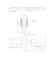
SMA-905连接头免除了FC、ST等常规通信用光纤连接头的角度定位键,螺纹锁紧的方式固定,在激光的工业、医疗连接中采用较多,其相关尺寸标准见下图:关键尺寸有插芯直径、插芯长度和螺帽规格,分别为3.172mm,9.8mm 以及1/4-36螺纹。
SMA-905对接耦合的法兰盘由于市场需求量不如FC、ST、SC、LC等庞大,一般为金属直接加工而成,较少有带陶瓷套筒的SMA-905法兰盘。
SMA-905相关的连接器还有SMA-906、插芯端面带让位孔或镶嵌宝石的SMA-905、SMA-906、以及某些公司差异化特意推出的D80等类似SMA-905的公制版本以及D200、QBH等超高功率版本。
在百瓦以及千瓦级别的大功率YAG激光传输中,这种简单的连接头已经不能满足散热等要求,各激光公司也开发出相应的高功率水冷光纤连接头,例如楚天激光就有相关专利《大功率水冷光纤装置》CN2343598Y。
但各激光厂家开发的大功率连接头一般都自用,国内市场上有待专业的大功率光纤连接厂家出现。
一次性医用激光光纤产品技术要求ruiertongjiguang
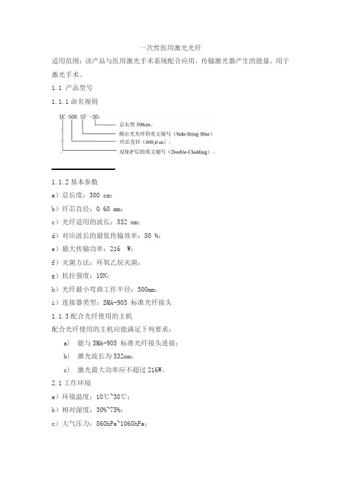
一次性医用激光光纤适用范围:该产品与医用激光手术系统配合应用,传输激光器产生的能量,用于激光手术。
1.1 产品型号1.1.1命名规则1.1.2基本参数a)总长度:300 cm;b)纤芯直径:0.60 mm;c)光纤适用的波长:532 nm;d)对应波长的最低传输效率:80 %;e)最大传输功率:216 W;f)灭菌方法:环氧乙烷灭菌;g)抗拉强度:10N;h)光纤最小弯曲工作半径:500mm。
i)连接器类型:SMA-905 标准光纤接头1.1.3配合光纤使用的主机配合光纤使用的主机应能满足下列要求:a) 能与SMA-905 标准光纤接头连接;b) 激光波长为532nm;c) 激光最大功率应不超过216W。
2.1工作环境a)环境温度:10℃~30℃;b)相对湿度:30%~75%;c)大气压力:860hPa~1060hPa;2.2 光纤性能2.2.1光纤长度:300cm±30cm,治疗部分长度:345mm±35mm。
2.2.2直径a)纤芯直径:0.60mm±0.06mm;b)裸光纤直径:1.05mm±0.10mm;c)光纤插入部分最大外径(治疗头外径):1.9mm±0.19mm。
2.2.3制造商应提供的产品信息制造商应在说明书或标记中至少提供以下产品信息:a)总长度;b)纤芯直径;c)光纤适用的波长;d)对应波长的最低传输效率;e)最大传输功率;f)抗拉强度;g)光纤最小弯曲工作半径。
2.3光学性能2.3.1光纤传输效率光纤平直放置时对532nm波长的激光传输效率应不小于80%。
2.3.2光纤传输效率不稳定度不大于±10%。
2.3.3光纤传输效率复现性不大于±10%。
2.3.4光纤端面出光角不超过 70°±20°。
2.4机械性能2.4.1光纤抗拉强度光纤传输体与连接头接合处的抗拉强度应不小于10N。
抗拉试验后,光纤传输效率应不小于试验前的90%。
905 纳米脉冲激光二极管 RLD90QZW 系列 谐振波 B-01 使用说明书
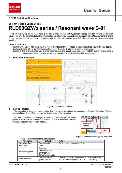
User’s GuideROHM Solution Simulator905 nm Pulsed Laser DiodeRLD90QZWx series / Resonant wave B-01This circuit simulate the resonant wave B-01 Time-Domain response of RLD90QZWx series. You can observe the resonant wave of not only the current but also the optical output waveform. You can customize the parameters of the components shown in blue, such as VIN, or peripheral components, and simulate the resonant wave B-01 Time-Domain with desired operating condition.General CautionsCaution 1: The values from the simulation results are not guaranteed. Please use these results as a guide for your design. Caution 2: Please refer to the Application note of Laser Diode for details of the technical information.Caution 3: The characteristics may change depending on the actual board design and ROHMstrongly recommend todouble check those characteristics with actual board where the chips will be mounted on.1 Simulation SchematicFigure 1. Simulation Schematic2 How to simulateThe simulation settings, such as simulation time or convergence options, are configurable from the ‘Simulation Settings’ shown in Figure 2, and Table 1 shows the default setup of the simulation.In case of simulation convergence issue, you can change advanced options to solve. Default statement in ‘Manual Options’ is a sets the transient analysis and parameter. You can modify it.Figure 2. Simulation Settings and execution3Simulation Conditions3.1 V2 parameter setupFigure 3 shows how the V2 parameters correspond to the VIN stimulus waveform.Figure 3. V2 parameters and its waveform4 RLD90QZW8_Po modelTable 3 shows the model pin function implemented. Note that RLD90QZWx series_Po is the behavior model for its optical output power response operation, and no protection circuits or the functions not related to the purpose are not implemented.4.1 Optical Output PowerRLD90QZWx series_Po model outputs optical output power in V [volts] unit. Optical Output Power insert model multiplies the output result by 1A and convert it to W [watts]. To monitor the optical output power in W [watts], select probe item ‘power_output’ from property of Optical Output Power insert model.Figure 4. Probe Items of Optical Output Power insert model5 Peripheral Components5.1 Bill of MaterialTable 4 shows the list of components used in the simulation schematic. Each of the capacitor and inductor has the parameters of equivalent circuit shown below. The default value of equivalent components are set to zero except for the ESR of C, and parallel resistance of L. You can modify the values of each component.5.2 Capacitor Equivalent Circuits(a) Property editor (b) Equivalent circuitFigure 5. Capacitor property editor and equivalent circuitThe default value of ESR is 0.01 Ω.5.3 Inductor Equivalent Circuits(a) Property editor (b) Equivalent circuitFigure 6. Inductor property editor and equivalent circuitThe default value of PAR_RES is 6.6 kΩ.(Note 1) These parameters can take any positive value or zero in simulation but it does not guarantee the operation of the IC in any condition. Refer to the datasheet to determine adequate value of parameters.6 Link to the product information and tools6.1 Laser DiodeRLD90QZW3 : 905 nm, 75 W, 225 μm Invisible Pulsed Laser Diode. [JP] [EN] [CN] [KR] [TW] [DE]RLD90QZW5 : 905 nm, 25 W, 70 μm Invisible Pulsed Laser Diode. [JP] [EN] [CN] [KR] [TW] [DE]RLD90QZW6 : 905 nm, 25 W, 50 μm Invisible Pulsed Laser Diode. [JP] [EN] [CN] [KR] [TW] [DE]RLD90QZW8 : 905 nm, 120 W, 270 μm Invisible Pulsed Laser Diode. [JP] [EN] [CN] [KR] [TW] [DE] Technical Articles and Tools can be found in the Design Resources on the product web page.NoticeROHM Customer Support System/contact/Thank you for your accessing to ROHM product informations.More detail product informations and catalogs are available, please contact us.N o t e sThe information contained herein is subject to change without notice.Before you use our Products, please contact our sales representative and verify the latest specifica-tions :Although ROHM is continuously working to improve product reliability and quality, semicon-ductors can break down and malfunction due to various factors.Therefore, in order to prevent personal injury or fire arising from failure, please take safety measures such as complying with the derating characteristics, implementing redundant and fire prevention designs, and utilizing backups and fail-safe procedures. ROHM shall have no responsibility for any damages arising out of the use of our Poducts beyond the rating specified by ROHM.Examples of application circuits, circuit constants and any other information contained herein areprovided only to illustrate the standard usage and operations of the Products. The peripheral conditions must be taken into account when designing circuits for mass production.The technical information specified herein is intended only to show the typical functions of andexamples of application circuits for the Products. ROHM does not grant you, explicitly or implicitly, any license to use or exercise intellectual property or other rights held by ROHM or any other parties. ROHM shall have no responsibility whatsoever for any dispute arising out of the use of such technical information.The Products specified in this document are not designed to be radiation tolerant.For use of our Products in applications requiring a high degree of reliability (as exemplifiedbelow), please contact and consult with a ROHM representative : transportation equipment (i.e. cars, ships, trains), primary communication equipment, traffic lights, fire/crime prevention, safety equipment, medical systems, servers, solar cells, and power transmission systems.Do not use our Products in applications requiring extremely high reliability, such as aerospaceequipment, nuclear power control systems, and submarine repeaters.ROHM shall have no responsibility for any damages or injury arising from non-compliance withthe recommended usage conditions and specifications contained herein.ROHM has used reasonable care to ensur e the accuracy of the information contained in thisdocument. However, ROHM does not warrants that such information is error-free, and ROHM shall have no responsibility for any damages arising from any inaccuracy or misprint of such information.Please use the Products in accordance with any applicable environmental laws and regulations,such as the RoHS Directive. For more details, including RoHS compatibility, please contact a ROHM sales office. ROHM shall have no responsibility for any damages or losses resulting non-compliance with any applicable laws or regulations.W hen providing our Products and technologies contained in this document to other countries,you must abide by the procedures and provisions stipulated in all applicable export laws and regulations, including without limitation the US Export Administration Regulations and the Foreign Exchange and Foreign Trade Act.This document, in part or in whole, may not be reprinted or reproduced without prior consent ofROHM.1) 2)3)4)5)6)7)8)9)10)11)12)13)。
SMA905光纤跳线
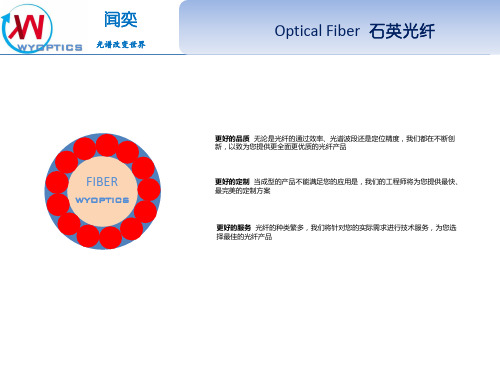
Optical Fiber 石英光纤
光纤的封装 -抗弯折抗拉多层金属铠甲,最外层PVC软管,金属网与塑胶多层 保护。 -不锈钢套管封装,多用于户外,戒腐蚀性环境; 光纤的配置 -Y形光纤,用于反射光谱测量; -分叉光纤,用于多通道光谱测量; -Z形光纤,用于需要参比光路的反射光谱测量; -X形光纤,用于荧光戒大角度反射光谱测量; -定制配置,可以根据用户的需求定制复杂配置的光纤
闻奕
光谱改变世界
Optical Fiber 石英光纤
wyoptics
wyoptics
闻奕
光谱改变世界
Optical Fiber 石英光纤
测量方式
产品应用
• 光学应用实验、研究测量等
• 光学荧光测量
• 反射测量 • 透过率测量 • 光学激发光检测
• 医用光检测器械
• 工业硅片、液体、光谱检测等 • 食品安全检测 • 紫外光对皮肤美容应用等
wyoptics
闻奕
光谱改变世界
Optical Fiber 石英光纤
• 芯数可根据客户需求自由变换
18+1
11
1000um*1 400um*10
10
5
闻奕
光谱改变世界
Optical Fiber 石英光纤
光纤应用[反射]
wy
wyoptics
闻奕
光谱改变世界
Optical Fiber 石英光纤
光纤应用[透射1]
wyoptics
闻奕
光谱改变世界
Optical Fiber 石英光纤
光纤应用[透射2]
本产品对于液体、气体、固体的透过率均可以测量,根据客户的需求可以自由变换高度厚度,如您有疑问请联系本公司工程师
医用石英光纤制品分为6种大功率激光治疗仪用石英光纤

1、大功率激光光纤2、照射光纤头3、无菌光纤针4、体内照射光纤5、体外照射光纤6、弥散光纤一、大功率激光治疗仪用石英光纤1.“治疗用激光光纤”与医用激光治疗仪配套应用,传输激光器产生的能量,用于激光手术。
2.产品规格型号:本产品由SMA905标准接头连接器、光纤、保护管三个部件组成。
光纤丝采用石英玻璃、SMA905标准接头连接器采用铜、保护管采用硅橡胶材料制成。
规格型号包括:CS-H200、CS-H300、CS-H400、CS-H500、CS-H600、CS-H800、CS-S276、CS-S365、CS-S550、CS-S800等,具体光纤芯径参数请参考本公司的硬树脂包层的石英光纤规格型号。
光纤传输效率:光纤总长度≤5m平直放置时,对应波长的传输效率不小于80%3.订货须知:本产品需无菌状态提供至少提前3周订货,因产品无菌检测需2周时间;本产品为非无菌状态提供至少提前1周订货;本产品正在办理注册证、目前仅用于向已取得激光治疗仪器整机注册(含治疗用激光光纤)的设备配套使用;本产品可根据客户要求定制。
4.产品照片:二、一次性使用口鼻腔内照射光纤头1.“一次性使用口鼻腔内照射光纤头”简称“光纤头”,依据《医疗器械分类规则(局令第15号)》及《医疗器械分类目录》本产品属于Ⅱ类6824医用激光仪器设备。
产品结构:产品由光纤丝、连接头和连接套组成,连接头与连接套的材料采用ABS材料组成。
传输效率不少于80%。
产品经环氧乙烷灭菌。
“光纤头”配合“低强度氦氖激光治疗仪”使用,“光纤头”起将氦氖激光引入人体的传导作用。
“光纤头”的使用方式亦应根据不同功效、种类的“氦氖激光治疗仪”而分别对待。
“光纤头”一般所传导的氦氖激光剂量为3~5mw,治疗时间约60分钟,与人体接触部位为口鼻腔内表面照射,不破坏人体组织。
“光纤头”经江苏省医疗器械检验所对“无菌试验、细胞毒性、致敏试验、刺激试验”等项均检测合格。
——检测报告号:(2002)字SC类第165号。
石英多模光纤共分8种

1、双包层光纤2、硬树脂包层光纤3、硅橡胶包层光纤4、聚酰亚胺涂层光纤5、侧发光光纤6、锥度光纤7、氟涂层光纤8、耐辐照光纤一、双包层光纤(HCS)1.技术说明石英双包层光纤按光谱传输范围分为紫外石英双包层光纤(UVHCS)和红外石英双包层光纤(IRHCS);数值孔径(NA):0.22±0.02、0.27±0.02;芯皮比(CCDR):1:1.04、1:1.05、1:1.1、1:1.2、1:1.4。
2.光纤光谱图如下:传输范围:UVHCS:190nm~1200nm;IRHCS:350nm~2500nm 透过率(波长632.8nm):≧99.7%/m;长期使用温度(丙烯酸树脂涂层):-40℃~80℃长期弯曲使用半径:300D(D为光纤包层外径);短期弯曲使用半径:100D(D为光纤包层外径);3.光纤结构图:1——光纤芯层(通光层)纯石英材料2——光纤皮层(光学包层)石英材料3——光纤涂覆层(保护层)树脂材料4.产品规格型号UVHCS系列规格芯径(μm)±2%包层外径(μm)±2%涂覆外径(μm)±5%UVHCS100/110100110180 UVHCS105/125105125240 UVHCS192/200192200245 UVHCS200/220200220280 UVHCS288/300288300500 UVHCS385/400385400550 UVHCS400/420400420600 UVHCS400/440400440600 UVHCS480/50048050700 UVHCS577/600577600900UVHCS600/630600630900 UVHCS800/8408008401200 UVHCS960/100096010001400 UVHCS1000/1100100011001400IRHCS系列规格芯径(μm)±2%包层外径(μm)±2%涂覆外径(μm)±5%IRHCS50/12550±2%125±2%245±5% IRHCS62.5/12562.5±2%125±2%245±5% IRHCS192/200192±2%200±2%245±5% IRHCS200/220200±2%220±2%280±5% IRHCS200/240200±2%240±2%400±5% IRHCS300/330300±2%330±2%500±5% IRHCS400/440400±2%440±2%600±5% IRHCS600/660600±2%660±2%900±5% IRHCS800/840800±2%840±2%1200±5% IRHCS800/880800±2%880±2%1300±5%5.订货须知:通光径在100~1000μm的特殊规格光纤可以根据要求定制。
光纤产品型号
2、石英光纤束打标规则: 石英光纤束产品出厂前应当打标识,标识共 2 行,具体规则如下:
型 光纤束直径
本批次第几条(三位数字) 本批次共几条(三位数字) 生产月份(1 月=A,2 月=B,3 月=C……) 生产年份(取后两位)
例如: S/N:T100-φ2
12D015001
表示芯径 600 微米紫外光纤,2012 年 1 月生产,此批投产 50 条,这是第 001 条。
1 两种以上接头时,按照接头的英文首字母顺序编写,首字母一样的按照第二位编写。 2 光纤接头 APC、PC 同时存在时,APC 在前。 3 具体光纤标识字母见《光纤型号编写规则》。
光纤产品型号编写规则
2、光纤跳线打标规则: 光纤跳线产品出厂前应当打标识,标识共 2 行,具体规则如下:
S/N: □ □ □□□□
光纤类型(光纤类型取光纤标号的第 3 个字母) 芯径
本批第几条(三位数字) 本批共几条(三位数字) 生产月份(1 月=A,2 月=B,3 月=C……) 生产年份(取后两位)
例如:
S/N: S600 12A050001
S/N : □ - □ □□□□
光纤类型 光纤束直径
本批次第几条(三位数字) 本批次共几条(三位数字) 生产月份(1 月=A,2 月=B,3 月=C……) 生产年份(取后两位)
例如:
S/N:BGOF50-φ2 12A100001
表示国产玻璃光纤,束直径 2mm,2012 年 1 月生产,此批投产 100 条,第 001 条。
表示,进口棒红外光纤透过 400-2500nm,单丝芯径 100μm,束直径 2mm,2012 年 4 月生产,此批投产 15 条,第 001 条。
5 复杂光纤束用字母“W”表示
SMA系列连接器是什么?它有何特点
SMA 系列连接器是什么?它有何特点
SMA 系列连接器是一种应用广泛的小型螺纹连接的同轴连接器,寿命长,性能优越、可靠性高,广泛用于微波设备和数字通信设备的射频回路射频同轴电缆或微带。
在无线设备上常用于单板上的GPS 时钟接口及基站射频模块的测试口。
现阶段手持对讲机*常见的接口,已经很普遍。
MPO(Multi-fiberPushOn)连接器为MT 系列连接器之一,MT 系列的插芯都采用插芯端面上左右两个直径为0.7mm 的导引孔与导引针(又叫PIN 针)进行精准连接。
MPO 连接器的紧凑设计,使MPO 跳线芯数多,体积小。
MPO 跳线被广泛应用于在布线过程中需要高密度集成光纤线路环境中,FTTX 及40/100GSFP、SFP+等收发模块或设备内外部的连接应用。
SMA简介
SMA的天线接口全称应为 SMA反级性公头(至于为什么这么叫我也不知道反正天线厂家的订单上是这么写的,E文是 SMA RP M) 就是天线接头是内部有螺纹的里面触点是针(无线设备一端是外部有螺纹里面触点是管)这种接口的无线设备是最最普及的 70% 以上的AP、无线路由和90%以上的PCI接口的无线网卡都是采用这个接口这个接口大小适中手持对讲机等设备也有不少是这个类型但里面的针和管却与无线设备相反的。
SMA分为很多种,极性方面的差异一个叫“SMA”,另一个叫“RP-SMA”,他们之间的差别就是:标准的SMA是:“外螺纹+孔”、“内螺纹+针”RP-SMA是:“外螺纹+针”、“内螺纹+孔SMA系列小型射频同轴连接器SMA MINIATURE RF COAXIAL CONNECTORSSMA系列产品是一种应用广泛的小型螺纹连接的同轴连接器,它具有频带宽、性能优、高可靠、寿命长的特点。
适用于微波设备和数字通信系统的射频回路中连接射频电缆或微带线。
Series of SMA products one application extensive small-scale coaxial person who join that whorl join, it has a reliable characteristic with longlife-span that the width, performance are excellent, high frequently. Suitable for the microwave equipment and body of the digital communication system and join the body in the cable or the micro-strip line frequently in the loop frequently.SMA系列产品是一种应用广泛的小型螺纹连接的同轴连接器。
钬激光光纤使用注明事项-新
钬激光光纤使用注明事项
(一)光纤在使用前的检测要求
1)光纤不使用时请将其盘绕在自带的纸盘上,光纤的SMA905金属端面要用塑料防尘帽锁
紧。
2)每次使用光纤时,先打开塑料防尘帽,并用光纤端面检测镜检测光纤的端面是否完好。
3)将光纤和检测镜对接,把光纤的尾端对着明亮的光源,观察光纤与端检仪表对接的端面情
况。
a)如果端面有脏东西,请用擦镜纸蘸无水酒精清洁。
清洁完后务必再次检查,保证光纤端
面的清洁,没有擦镜纸的纤维残留在光纤。
对着灯光观察时,完好的光纤的内芯呈现为明亮完整的圆点
b)如果检查发现光纤端面无法清洁或者端面已经被打坏,请不要再使用这条光纤(继续使
用会损坏其他光学元件)
对着灯光观察时,损坏的光纤内芯呈现为阴暗的黑点
二、切割光纤及端面处理
1) 手术光纤在使用中光纤尾端会有损耗,我们需要对其进行再处理。
光纤的外层包裹着一层护套,我们首先要用剥离器将其剥离。
不同芯径的光纤对应使用不同的剥离器。
550um 芯径的光纤护套剥离器剥离光纤护套
4)重新剥离过的光纤的裸露部分通常过长,且端面不平整,我们需要用光纤切割刀来切割
处理。
光纤端面切割刀
用刻刀处理光纤端面, 保证裸露的光纤长度为2~3mm
处理以后的光纤端面
3) 用机器的瞄准光为参考光来判别光纤的端面的平整性.
c)把光纤接到主机上,开启机器,在使用界面上将瞄准光调到最亮. 如果光纤的尾端处
理平整,出射的瞄准光光斑为没有缺损或拖尾的同心圆(如下图).
4) 如果光斑有明显的缺损或拖尾则需要重新处理端面。