纸箱爆裂强度标准 tappi 810
纸箱爆破力测试标准
纸箱爆破力测试标准一、测试目的本测试标准的目的是评估纸箱对外部施加压力的承受能力,以及在压力作用下纸箱的变形、渗漏和破裂等情况。
通过本测试,可以了解纸箱在不同压力条件下的性能表现,为包装设计、材料选择和质量控制提供依据。
二、测试原理本测试基于压力试验机对纸箱施加压力,观察纸箱在压力作用下的表现。
通过压力传感器记录压力曲线,并观察纸箱的变形、渗漏、破裂等情况。
测试过程中,需严格控制压力加载速度、保持纸箱表面清洁和平整,以确保测试结果的准确性。
三、测试设备1.压力试验机:用于对纸箱施加压力,应具备可调节的加载速度和压力范围。
2.压力传感器:用于测量施加在纸箱上的压力,应具有高精度和稳定性。
3.测试平台:用于放置纸箱,应保持水平、稳定,确保纸箱不会发生滑动或倾斜。
4.摄像装置:用于记录测试过程中纸箱的变形、渗漏和破裂情况。
四、试验步骤1.将纸箱放置在测试平台上,保持纸箱表面清洁、平整。
2.将压力传感器放置在纸箱表面,确保与纸箱表面完全接触。
3.启动爆破力测试设备,对纸箱施加压力,并记录压力曲线。
加载速度应控制在规定范围内,以确保测试结果的准确性。
4.观察纸箱的变形、渗漏、破裂等情况,记录测试结果。
在测试过程中,应保持摄像装置处于工作状态,以便记录纸箱的实时变化。
五、测试结果分析根据测试结果,对纸箱的爆破力性能进行分析。
比较在不同压力条件下的变形、渗漏和破裂情况,评估纸箱在不同应用场景下的适用性。
同时,可对不同类型、材质和结构的纸箱进行对比分析,以便选择更具有优势的包装材料和设计方案。
六、测试报告1.测试目的:明确本次测试的目的、关注的性能指标等。
2.测试原理:简要介绍测试的方法、原理和依据的标准。
3.测试设备:列出在测试过程中使用的设备和仪器,包括型号、规格和制造商等信息。
4.试验步骤:详细描述试验过程,包括纸箱的准备、压力加载速度控制、摄像装置的使用等。
纸箱抗压试验机测试方法与标准 抗压试验机技术指标

纸箱抗压试验机测试方法与标准抗压试验机技术指标纸箱抗压试验机测试方法与标准_机械/仪表_工程科技_专业资料。
纸箱抗压试验机测试方法与标准纸箱抗压强度测试标准及测试方法纸箱抗压强度测试标准及测试方法,昆山海达仪器为你解答:纸箱抗压强度测试紧要用于各种包装体、纸箱之耐压强度、以防范各种包装体因强度不够导致产品在使用、搬运、堆叠、仓储、运输过程中产品变形、损坏之不良现象发生。
并可做堆码测试,试验的结果可作为工厂堆放成品包装箱高度的紧要参考,而纸箱抗压强度又有以下几点要求: 一、纸箱外观质量: 1、封闭质量:箱体四周无漏洞,各箱盖合拢后无参差和离缝; 2、尺寸公差:箱体内径与设计尺寸公差应保持在大箱5mm,小箱3mm,外形尺寸基本一致; 3、印刷质量:图案、字迹印刷清楚,色度一致,光亮明丽;印刷位置误差大箱不超过7mm,小箱不超过 4mm; 4、盖折叠次数:瓦楞纸箱摇盖经开、合180 度往复折叠 5 次以上,一、二类箱的面层和里层、三类箱里层裂缝长度总和不大于 70mm;此外,要求接合规范,边缘整齐,不叠角,箱面不允许有明显损坏或污迹等. 二、纸箱抗压强度及影响因素:纸箱耐压强度是很多商品包装要求的较为紧要的质量指标,测试时将瓦楞纸箱放在两压板之间,加压至纸箱压溃时的压力,即为纸箱耐压强度,用 KN 表示。
预定纸箱耐压强度纸箱要求有确定的耐压强度,是由于包装商品后在贮运过程中堆码在最低层的纸箱受到上部纸箱的压力,为了不至于压塌,必需具有合适的抗压强度,纸箱的耐压强度用下列公式计算: P=KW(n—1)式中 P————纸箱耐压强度,N W————纸箱装货后重量,N n————堆码层数 K————堆码安全系数堆码层数 n 依据堆码高度 H 与单个纸箱高度 h 求出,n=H/h 堆码安全系数依据货物堆码的层数来确定,国标规定:贮存期小于 30d 取 K=1.6 贮存期 30d—100d 取K=1.65 贮存期大于 100d 取 K=2.0 确定纸箱抗压强度的方法由于受生产过程中各种因素的影响,最后用原材料生产的纸箱抗压强度不愿定与估算结果完全一致,因此最后精准明确确定瓦楞纸箱抗压强度的方法是将纸箱恒温湿处理后用纸箱抗压试验机测试;对于无测试设备的中小型厂,可以在纸箱上面盖一木板,然后在木板上堆放等量的重物,来大致确定纸箱抗压强度是否充分要求;据原材料计算出纸箱抗压预定了纸箱抗压强度以后,应选择合适的纸箱板、瓦楞原纸来生产瓦楞纸箱,避开盲目生产造成的挥霍;依据原纸的环压强度计算出纸箱的抗压强度有很多公式,但较为简练应用的是 kellicutt 公式,它适合于用来估算 0201 型纸箱抗压强度。
包装纸箱质量标准(小编整理)

包装纸箱质量标准(小编整理)第一篇:包装纸箱质量标准包装纸箱质量标准1、双瓦楞(5层)每层每平方克重及纸质要求:第1层(面纸)175G/㎡国产牛皮纸A级第3层(中间夹层)150G/㎡国产牛皮纸A级第5层(里纸)150G/㎡国产牛皮纸A级第2/4层(瓦楞层)100G/㎡高瓦楞2、摔箱测试外箱是否异常(纸箱是否破损或者变形,产品是否破损或变形);视检外箱垂直四条棱边(或面)是否弯曲。
3、堆箱测试采用附件的方法,视检底层外箱是否异常(变形,开裂,产品顶破纸箱,封箱带崩开,产品受损)。
4、打开箱盖翻转270度,往复3次,视检折面开裂小于5CM为合格。
5、瓦愣纸箱含水率12%±4(手感是否潮湿)。
6、唛头文字及图案清晰正确,深浅一致,位置正确。
7、彩盒依据尺寸大小面张每平米克重:60CM见方以下300G;60CM见方以上350G。
彩盒印刷应清晰鲜亮,图案与产品一致。
8、所用胶水为淀粉粘合剂。
9、纸箱不能打钉。
10、纸箱不允许使用打包带。
11、封箱带宽度一般不小于6CM。
12、必要时外箱内应加填充物(隔挡、衬垫、底座等)使产品在外箱各方向受力情况下在箱内处于稳定状态。
13、纸箱在运输、贮存应避免受到雨淋、爆晒、受潮和污染。
附件:纸箱耐压强度纸箱要求有一定的耐压强度,是因为包装商品后在贮运过程中堆码在最低层的纸箱受到上部纸箱的压力,为了不至于压塌,必须具有合适的抗压强度,纸箱的耐压强度用下列公式计算:P=KW(n-1)式中P----纸箱耐压强度W----纸箱装货后重量 n----堆码层数K----堆码安全系数堆码层数n根据堆码高度H与单个纸箱高度h求出,n=H/h 堆码安全系数根据货物堆码的层数来确定,国标规定:贮存期小于30天取K=1.6 贮存期30-100天取K=1.65 贮存期大于100天取K=2.0 具体操作时在纸箱上面盖一木板,然后在木板上堆放等量的重物。
参考资料:GB 5034-85 《出口产品包装用瓦楞纸板》第二篇:Xxx包装纸箱的质量标准Xxx包装纸箱的质量标准 1.目的:建立xxx包装纸箱的质量标准。
纸箱破裂强度试验机操作指导书A0
一、 目的 为规范仪器使用,保证纸箱强度测量数据的可靠性,延长仪器的使用寿命。
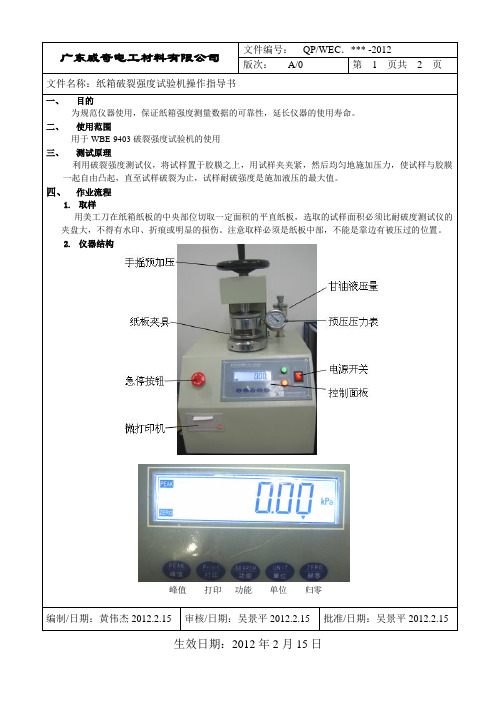
二、 使用范围 用于 WBE-9403 破裂强度试验机的使用
三、 测试原理 利用破裂强度测试仪,将试样置于胶膜之上,用试样夹夹紧,然后均匀地施加压力,使试样与胶膜
一起自由凸起,直至试样破裂为止,试样耐破强度是施加液压的最大值。
四、 作业流程
1. 取样 用美工刀在纸箱纸板的中央部位切取一定面积的平直纸板,选取的试样面积必须比耐破度测试仪的
夹盘大,不得有水印、折痕或明显的损伤。注意取样必须是纸板中部,不能是靠边有被压过的位置。 2. 仪器结构
峰值 打印 功能 单位 归零
编制/日期:黄伟杰 2012.2.15 审核/日期:吴景平 2012.2.15 批准/日期:吴景平 2012.2.15
生效日期:2012 年 2 月 15 日
广东威奇电工材料有限公司
文件编号: QP/WEC.*** -2012
版次: A/0
第 2 页共 2 页
文件名称:纸箱破裂强度试验机操作指导书
3. 开机 连接220V电源,按下电源开关。注意急停按钮是没有被按下时才可以开机。 检测液压油位置是否够,液压表是否正常。
杯、管路,和及时更换甘油。具体更换方法请参照仪器说明书。 3. 橡皮膜保养。
由于橡皮膜是核心部件,日常不能用有腐蚀性的液体清洗,保证橡胶部位表面光滑干净。 当长期不用,橡皮膜易老化;测试次数过频繁,每天10次以上,持续1~2个月;长期做高压测试时, 橡皮膜都容易破损,需要用厂家仪器附带的标准铝箔片对仪器校准,铝箔片标准破裂强度为11.61± 0.14kgf/cm2,当仪器偏差大于±0.5%时,必须更换橡皮膜。具体更换方法请参照仪器说明书。
4. 单位设置 按“单位”按钮,把液晶屏内的单位调到KPa。
纸箱质量指标
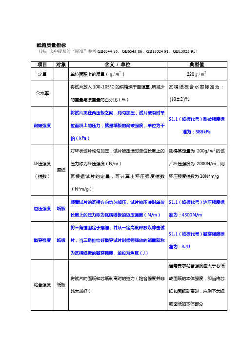
瓦楞纸板含水率标准为:
含水率(10ຫໍສະໝຸດ ± 2 ) %耐破强度将试片夹在两压板之间,均匀加压, 将试片夹在两压板之间,均匀加压,试片破裂时单 在两压板之间 S1.1(纸板代号) S1.1(纸板代号)耐破强度标 位面积上的压力,就是纸板的耐破强度,单位为千 位面积上的压力,就是纸板的耐破强度, 准为: 准为:588kPa kPa) 帕(kPa) 对环状试片均匀加压,试片被压溃时单位长度上的 测得某定量为 200g/ m 2 的试 压力称为环压强度(N/m) 片环压强度为 2000N/m,则环 再根据试片的定量, 可计算出环压强度指数 (N*m/g) 压强度指数为 10N*m/g 顺着试片的瓦楞方向均匀加压,试片被压溃时单位 S1.1(纸板代号)边压强度标 顺着试片的瓦楞方向均匀加压, S1.1(纸板代号) 长度上的压力称为瓦楞纸板的边压强度 N/m) 为瓦楞纸板的边压强度( 准为: 长度上的压力称为瓦楞纸板的边压强度(N/m) 准为:4500N/m 将三角锥固定于摆锤, 将三角锥固定于摆锤,并从一定高度释放以冲击试 S1.1(纸板代号) S1.1(纸板代号)戳穿强度标 片,当三角锥恰好戳穿试片时摆锤释放的能量就称 准为: 准为:3.4J 为瓦楞纸板的戳穿强度,单位为焦耳( 为瓦楞纸板的戳穿强度,单位为焦耳(J) 将试片的面纸和芯纸剥离时的拉力(粘合强度并非 越大越好) 纸箱能承受的最大压力,称为它的抗压强度( 纸箱能承受的最大压力,称为它的抗压强度(N) 验方法:在一定温度(20° 和湿度(65%) 实验方法:在一定温度(20°C)和湿度(65%)下, 压板对纸箱均匀加压,纸箱被压溃时的压力就是该 压板对纸箱均匀加压, 纸箱的抗压强度 通常要求粘合强度应大于芯纸 或面纸的本体强度,即当将芯 纸和面纸剥离时,应剥下芯纸 或面纸的本体部分 纸箱的抗压强度需求应根据 运输环境,运输周期, 运输环境,运输周期,内装物 重量和存储堆码高度而定
纸箱纸板的耐破强度是指以标准规定的方式
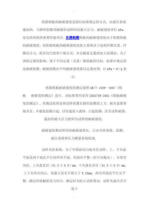
纸箱纸板的耐破强度是指以标准规定的方式,由液压系统施加的,当弹性胶膜顶破圆形试样时的最大压力。
耐破强度单位kPa,是包括用纸的重要性能项目。
瓦楞纸箱纸板的耐破强度取决于纸箱纸板的耐破强度,而纸箱纸板的耐破强度高低主要取决于造纸纤维长度。
纤维结合力、纸页均匀度和干燥方式,并且随着定量的加大而增加。
为了消除定量的影响,便于不同定量(克重)箱纸板的比较,标准中规定的是耐破指数。
耐破指数由平均耐破强度除以定量而得,以kPa·㎡/g表示。
纸箱纸板耐破强度的测定按照GB/T 1539—2007《纸板耐破度的测定》进行,该标准等同采用ISO2759:2001《纸板耐破度的测定》。
其测试原理是将试样放置在圆形胶膜的上方,被夹盘紧密地夹住,并避免胶膜凸起。
以恒速泵入液体,凸起胶膜,直至试样破裂,施加的最大压力值即为试样的耐破强度。
耐破强度测试所用的耐破强度仪。
它由夹持系统、胶膜、液压系统和压力测量系统组成。
试样夹持系统:为了牢固而均匀地夹住试样,上、下夹盘平面是两个彼此平行的环形平面,环面应平整(但不应抛光),并带有沟纹。
上夹盘直径(31.5士0.5)mm,下夹盘孔直径(31.5士0.5)mm。
上下夹环应同心,其最大误差不得大于0.25mm。
两夹环彼此平行且平整。
测定时接触面受力均匀。
测定时为防止试样滑动,试样夹盘应具不低于690kPa的夹持力。
胶膜:胶膜是圆形的,由天然橡胶或合成橡胶制成,不应加填料或添加剂。
胶膜外表面被牢固地夹持着,在非工作状态下,胶膜相对固定胶膜的夹盘外表面约低5.5mm。
胶膜材料和结构应使胶膜凸出下夹盘的高度与弹性助力相适应,即凸出高度:(10士0.2)mm,其阻力范围为170kPa—220kPa;凸出高度:(18士0.2)mm,其阻力范围为250kPa—350kPa。
胶膜在使用时应定期检查,当凸出高度不能满足要求时应及时更换。
液压系统:向胶膜内表面提供持续的液压,直至试样破裂。
纸箱破裂强度试验报告

(Approval)
审核
(Confirmed)
试验者
(Tester)
纸箱破裂强度试验报告(Carton broken intensity test report)
Charge No.﹕
试验日期
(Test date)
No.:
试件
(Trial product)
料号
(Part No.)
NB08934
品名
(Itemname)
纸外箱-1入
315×315×520mm
规格
(Specifications)
样本编号(Sample No.)
测试部位(Test part)
1号箱
(No.1carton)
2号箱
(No.2carton)
3号箱
(No.3carton)
判定标准
(Specification)
正面(Facade)
(Kgf/cm2)
1
14.9
1.边缘压力:3~5Kgf/cm2
(Fringe pressure:3~5Kgf/cห้องสมุดไป่ตู้2)
■研发打样确认(R&D department sample confirm)其它(Others)
试验原理
(Test principle)
用油液压给橡皮膜球力,把纸箱顶破并记录其顶破时力数值.
试验环境
(Test environment)
1.环境温度27℃±2;湿度40%±5%RH.
试验设置
(Test setup)
2.根据该纸箱工程图纸
要求其最小破裂强度为(According to the requirement of engineering design of the carton, the smallest broken intensity is):14Kgf/cm2
纸箱耐破强度测试方法
纸箱耐破强度测试方法1范围本标准规定了以液压增加法测定瓦楞纸板的耐破强度的方法。
本标准适用于耐破度为350-5500kpa的瓦楞纸板。
2引用标准a)中华人民共和国国家标准GB/T6545-1998b)GB450-89纸和纸板试样的采取c)GB10739-89纸浆、纸和纸板试样处理与试验的标准大气3试验原理将闭幕式样置于胶膜之上,用试样夹夹紧,然后均匀地施加压力,使试样与胶膜一起自由凸起,直至试样破裂为止。
试样耐破度是施加液压的最大值。
4试验仪器a)试样夹盘系统:上夹盘孔直径(±)mm,下夹盘孔直径(±)mmb)上下夹环应同心,其最大误差不得大于0.25mm。
两夹环彼此平行且平整。
测定时接触面受力均匀。
测定时为防止试样滑动,试样夹盘应具有不低于690kpa的夹持力。
但这样的压力一般会使试样的瓦楞压塌,应在报告中注明。
c)胶膜胶膜是圆形的,由弹性材料组成。
胶膜被牢固地夹持着,它的上表面比下夹环的顶面约低5.5mm。
d)胶膜材料和结构应使胶膜凸出下夹盘的高度与弹性阻力相适应,即:凸出高度为10mm时,其阻力范围为(170-220)kpa;凸出18mm时,其阻力范围为(250-350)kpa。
5试样的采取和处理a)试样的采取按GB450的规定进行。
b)试样应按GB10739的规定进行温湿处理。
c)试样面积必须比耐破度测定仪的夹盘大,试样不得有水印、挤痕或明显的损伤,在试验中不得使用曾被夹盘压过的试样。
6测试步骤a)在条规定的大气条件下进行载样和试验。
b)开启试样的夹盘,将试样夹紧在两试样夹盘的中间,然后开动测定仪,以(170±15)ml/min的速度逐渐增加压力。
c)在试样爆破时,读取压力表上指示的数值。
然后松开夹盘,使读数指针退回到开始位置。
当试样有明显滑动时应将数据舍弃7结果表示以正反面各10个贴向胶膜的试样进行测定,以所有测定值的算术平均值(kpa)表示。
8试验报告a)最终测试结果合格/不合格;b)接下去如果操作改进如果是不合格;c)本国家标准的编号d)样品种类、规格;e)试验所用的标准;f)试验场所的大气条件;g)所用试验仪的型号和加压速度;h)试验结果的算术平均值;其他有助于说明试验结果的资料。
- 1、下载文档前请自行甄别文档内容的完整性,平台不提供额外的编辑、内容补充、找答案等附加服务。
- 2、"仅部分预览"的文档,不可在线预览部分如存在完整性等问题,可反馈申请退款(可完整预览的文档不适用该条件!)。
- 3、如文档侵犯您的权益,请联系客服反馈,我们会尽快为您处理(人工客服工作时间:9:00-18:30)。
Names of suppliers of testing equipment and materials for this method may be found on the Test Equipment Suppliers list in the bound 1set of TAPPI Test Methods, or may be available from the TAPPI Technical Operations Department.Approved by the Fiberboard Shipping Container Testing Committee of the Corrugated Containers DivisionTAPPIT 810 om-98SUGGESTED METHOD – 1966OFFICIAL TEST METHOD – 1980REVISED – 1985REVISED – 1992REVISED – 1998© 1998 TAPPIThe information and data contained in this document were preparedby a technical committee of the Association. The committee and theAssociation assume no liability or responsibility in connection with theuse of such information or data, including but not limited to anyliability or responsibility under patent, copyright, or trade secret laws.The user is responsible for determining that this document is the mostrecent edition published.Bursting strength of corrugated and solid fiberboard1.ScopeThis method describes the procedure for measuring the bursting strength of single wall and double wall corrugated and solid fiberboard. It is not designed to be used for the bursting strength of paper (TAPPI T 403 "Bursting Strength of Paper"), paperboard and linerboard (TAPPI T 807 "Bursting Strength of Paperboard and Linerboard"), or triple wall corrugated board.2.SignificanceThe bursting strength of combined board is primarily an indication of the character of the materials used in manufacturing a fiberboard box and has value in this respect. Bursting strength of combined board is an optional requirement of the various carrier regulations for shipping containers. The bursting strength of the component paperboard is an important control test in the paperboard mill since the conformity of the finished container is generally controlled by the bursting strength of the paperboard. Triple-wall corrugated board cannot be tested suitably by the bursting method. Testing of double-wall board is of questionable accuracy since it is rarely possible to get sufficiently simultaneous bursts of the multiple facings. The test is simple and rapid to execute, but it must be recognized that it is subject to serious errors if instrument, diaphragm, and gages are not properly maintained or if improper procedures are used (1, 2, 3).3.Apparatus3.1Bursting tester , consisting of the following:13.1.1Means for clamping the test specimen between two annular, plane surfaces having fine concentric tool marks to minimize slippage. The upper clamping platen (clamping ring) has a minimum diameter of 95.3 mm (3.75 in.),a minimum thickness of 9.53 mm (0.375 in.), and a circular opening of 31.50 ± 0.03 mm (1.240 ± 0.001 in.) diameter.The lower edge of the opening (side in contact with the board) has a 0.64 mm (0.025 in.) radius. The lower clamping surface (diaphragm plate) has a thickness of 5.56 ± 0.08 mm (0.219 ± 0.003 in.) with an opening 31.50 ± 0.03 mm (1.240± 0.001 in.) in diameter and an overall diameter at least as large as the upper clamping plate.. The upper edge of the opening (in contact with the board) has a 0.41 mm ± 0.1 mm (0.016 ± 0.004 in.) radius and the lower edge of the opening (in contact with the rubber diaphragm) has a radius of 3.1 ± 0.1 mm (0.122 ± 0.004 in.) to prevent cutting the rubber when pressure is applied. The upper clamping ring is connected to the clamping mechanism through a swivel joint tofacilitate an even clamping pressure. The openings in the two clamping plates are required to be concentric to within 0.13 mm (0.0051 in.) and their clamping faces flat and parallel (see T 807 Appendix A.1.1).3.1.2 A molded (disk-shaped) diaphragm requiring a pressure of not less than 160 kPa nor more than 210 kPa (not less than 23 psi nor more than 30 psi) to distend it to a height of 9.53 mm (0.375 in.) above the diaphragm plate (see T 807, Appendix A.1.2.)3.1.3Means of forcing liquid into the pressure chamber below the diaphragm at a steady rate of 170 ± 16 mL/min (0.045 ± 0.004 gal/min). This pressure shall be generated by a motor-driven piston forcing a liquid (glycerin) into the pressure chamber of the apparatus (see T 807, Appendix A.1.3).3.1.4 A Bourdon pressure gage of the maximum reading or the lazy hand type. The scale should have a radius of 47.6 mm (1.875 in.) with graduations extending over a minimum arc of 270° indicating bursting pressure in kPa or psi, with an accuracy of 0.5% of full scale, and have sufficient capacity so that all readings can be maintained in the middle half of the scale. In its operating position, have the gage inclined between horizontal and not over 30° from the horizontal. When more than one gage is mounted on a single apparatus, only the gage on which the measurement is being made is open to the hydraulic system so as not to reduce the rate of distention of the sample.3.1.5As an alternate to 3.1.4, a pressure transducer with suitable signal processing circuitry to display the maximum bursting pressure may be used provided it gives comparable results.3.1.6Electronic instruments are now available that automate and speed up the testing procedure. These instruments must maintain the critical elements of 3.1.1 through 3.1.3.NOTE 1:Care should be taken when comparing results between bourdon tube and electronic measuring systems. Differences in test results can arise due to differences in system expansibility and speed of data acquisition.3.1.7 Vernier caliper with micrometer gage to measure penetration of the upper clamping platen into the board.4.Calibration4.1Calibrate apparatus as per Instrument Manufacturers specifications.4.2Appendix A.1 of TAPPI T 807 describes a calibration procedure for one manufacturers apparatus.5.Sampling and test specimens5.1Solid fiberboard5.1.1From each test unit obtained in accordance with TAPPI T 400 "Sampling and Accepting a Single Lot of Paper, Paperboard, Containerboard, or Related Product," prepare five specimens at least 305 × 305 mm (12 × 12 in.). If the dimensions of each sheet of the test unit are too small, then use specimens no less than 102 mm (4 in.) wide and of sufficient length or number to permit a total of 20 bursts.5.2Corrugated board5.2.1From each test unit obtained in accordance with T 400, prepare five specimens at least 305 × 305 mm (12 × 12 in.). If size does not permit this, take specimens no less than 152 mm (6 in.) wide and of sufficient length or number to permit a total of 20 bursts.6.ConditioningCondition all specimens prior to testing and conduct tests in an atmosphere in accordance with TAPPIT 402 "Standard Conditioning and Testing Atmospheres for Paper, Board, Pulp Handsheets, and Related Products."7.Procedure7.1Solid fiberboard7.1.1Insert the specimen between the clamping ring and diaphragm plate, then apply a clamping pressure of 690 kPa (100 psi) either manually, pneumatically, or hydraulically and verify the pressure applied to the specimen. The specimen must not slip during the test.7.1.2Apply the bursting pressure by forcing the piston forward until the diaphragm ruptures the specimen. Record the maximum pressure registered.7.1.3Allot a minimum area of 102 x 102 mm (4 × 4 in.) for each burst to prevent the clamping areas from overlapping. Make an equal number of bursts from each side of the specimen. Arrange that no more than one burst fromeach side of the specimen falls in the same line of machine formation. Make no test on areas containing wrinkles, creases, or other obvious imperfections. Make a minimum of 6 bursts on each 305 × 305 mm (12 × 12 in.) specimen and a maximum of 10 bursts to determine the average bursting strength of the material tested.7.2Corrugated board7.2.1Insert the specimen between the clamping ring and the diaphragm plate. Apply a clamping pressure so that the top compression ring moves into the board to a depth as follows: "A" flute 2.08 ± 0.05 mm (0.082 ± 0.002 in.); "B" flute 0.81 ± 0.05 mm (0.032 ± 0.002 in.); "C" flute 1.62 ± 0.05 mm (0.062 ± 0.002 in.) and for Double Wall 3.05± 0.07 mm (0.12 ± 0.003 in.). The specimen must not slip during the test. Apply the bursting pressure by forcing the piston forward until the diaphragm ruptures the specimen. Record the maximum pressure registered.NOTE 2:On some testers equipped with a clamping wheel this corresponds to: "A" flute 3/4 turn; "B" flute 1/4 turn; "C" flute ½ turn and double wall 1 turn. Due to the surface and frictional characteristics of the board, the penetration depth to prevent slippage couldvary by +1/4 of a turn. If the tester is equipped with a hand wheel, pneumatic or hydraulic loading system adjust clamping pressureso that the sample will just slip between the clamping rings, measure the distance between the yoke and top clamping ring (see Fig.1), and adjust the pressure to get the specified penetration depth. There should be no slipping during the test, if slippage does occurincrease the penetration depth.7.2.2On corrugated board a minimum area of 152 × 152 mm (6 × 6 in.) is required for each burst. A22maximum of four bursts, two from each direction, is therefore made on each 930 cm (1 ft) specimen. A margin of at least 25 mm (1 in.) is left between the periphery of the clamping ring and the edge of the specimen. Locate the bursts so that not more than one burst from each direction is made in line with the same corrugation. Make a minimum of 20 bursts.NOTE 3:On testers with adjustable clamp pressure (pneumatic or hydraulic) the following alternative clamp procedure can be used.Determine the clamping force required to collapse the flutes of the test material. Reduce the clamp pressure by 35 kPa (5 psi) torun the burst tests.NOTE 4:Occasionally a "double pop" may occur on some corrugated materials. These results should be included in the report and labeled as double pops.8.Report2For each test unit report the average of the test determinations in kilopascals (or in lb/in. equivalent to kPa/6.89) to three significant figures.NOTE 5:For purposes of determining compliance with the optional carrier classification requirements, Uniform Freight Classification Rule41 and National Motor Freight Classification Item 222 specify a minimum bursting test rather than an average of the testdeterminations. These rules state, in effect, that only one burst (out of the six prescribed) is permitted to fall below the minimumtest required. Board failing to pass the foregoing will be accepted if, in a retest consisting of 24 bursts, not over 4 bursts fall belowthe minimum test required.9.Precision9.1Repeatability (within a laboratory) = 5.7%9.2Reproducibility (between laboratories) = 13.5%9.3The above values were obtained using test results, each an average of 20 determinations among 12 laboratories on 6 different corrugated combinations. The interlaboratory study was conducted in accordance with TAPPI T 1200 "Interlaboratory Evaluation of Test Methods Used with Paper and Board Products" by the Fibre Box Association Technical Committee, 1971-2.10.KeywordsCorrugated boards, Fiber boards, Burst strength.。