
MACKIE HR824示范级有源监听音箱说明书
0 dB
Ð2dB Ð4 dB
+2dB 0 dB
Ð2dB
10kHz
20
10 0Hz
ACO US TIC SP ACE
ROOM COMP E N SATIO N
HIGH FREQ.
¥ 0dB (START HERE) GUARANTEED FLAT USE FOR MOST APPLICATIONS
¥ +2dB: US E IF YOUR MIXES TRANSLATE BRIGHT
SERIAL NUMBER
SIGN AL IN PUTS BAL /UNBAL
PHONE
(10 k B RIDGING )
XLR
MAINS INP UT
MANUF ACTURING D ATE
1 20 VAC 60 Hz 10 0W
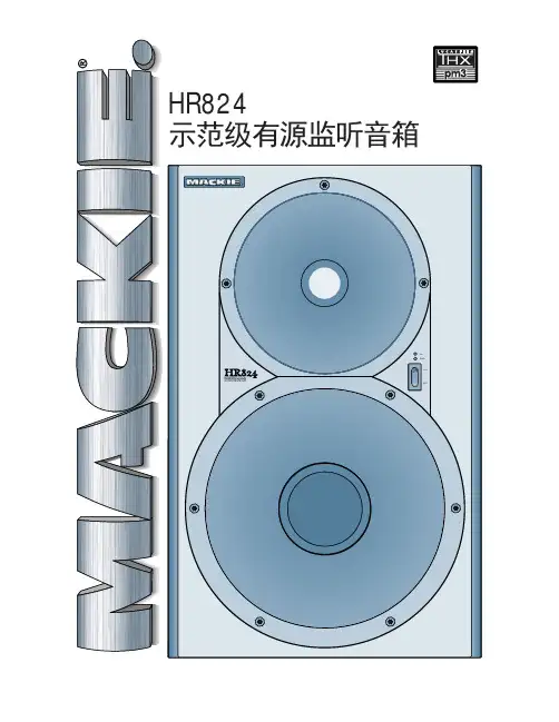
后背板功能描述
信号输入:采用AES/IEC标准的XLR及TRS接口,可以接受外 部输入的平衡/非平衡音频信号,接线方式如下:
CAUTION
RISK O F ELECTRIC SH OC K DO NO T O PEN
WARNING: TOREDUCETHERISKOFFIREORELECTRICSHOCK, DONOT
EXPOSETHISEQUIPMENTTORAINORMOISTURE. DONOTREMOVECOVER. NOUSERSERVICEABLEPARTSINSIDE. REFERSERVICINGTOQUALIFIEDPERSONNEL.
先进技术及设计
当我们意识到有源监听音箱的理论上的优势时, 我们由零开始设计HR824。这就决定了从一开始它就不 同于其它的有源监听音箱。 在开始设计前,我们做了大量相关设备、人力的 评估,我们设立了全新的工程部门,聘请了具有丰富 经验的音箱设计师,装备了许多其它公司梦寐以求的 极为先进的测试设备,MACKIE使用的技术有FEA:功能 强大的计算机仿真程序,FFT:实时激光测振分析仪, 以及使声学设计从"伏都教"转向真正的科学的新技术。
环形电源变压器
低频EQ
37Hz (通常位置) 47Hz 8 0Hz
+ 中压 VDC Ð
+ 低压 VDC Ð
动作检测
+ 高压 VDC
Ð
低频功率放大器
到削波检测 低频输出
低音单元
静音 低音伺服控制环路
检测电阻
技术参数
箱体结构
材料及结构: 3/4英寸(19mm)厚MDF板主体结构,1英寸
(25.4mm)厚 MDF前面板(带弧形防声衍射结构)
HR824剖面图 技术特点 - 采用名厂扬声器单元(高音---西雅士, 中低音---威法) - 高强度特厚MDF板坚固箱体结构 - 内部前级电子分频,双功率放大器 - 持续过载信号柔性压缩 - 独立高低音单元过载探测保护 - 声场摆位补偿电路
- 过热保护、低电压保护 - 已通过卢卡斯THX PM3认证,并针对杜比AC-3 及DTS系统作专门的优化设计
QUARTER HALF WHOLE (NORMAL)
ACOUSTIC SPACE
80Hz 47Hz 37Hz
LOW CUT
(NORMAL )
LOW FREQ
Ð2dB 0 +2dB (NORMAL)
HIGH FREQ.
ª
INTERNAL AMPLIFICATION
OFF AUTO ON ON
POWER MODE
C
0 dB
Ð3dB
LOW CUT
LOW CUT
24dB/oct BUTTERWORTH
37Hz 47Hz 80H z
LOW FREQ
¥ USE 80Hz TO EMULATE SMALL SPEAKER ¥ USE 47Hz FOR NORMAL LF PERFORMANCE
¥ USE 37Hz FOR NORMAL EXTENDED LOW FREQ PERFORMANCE
"H"支撑梁
被动辐射单元
内置功率 放大器
无源--功放驱动--有源 有明显的迹象表明无源音箱在衰落,由于它依赖 于原始的被动式分频器,无谓的消耗有用功率而且完 全依赖外置功放。无源设计达不到有源音箱的精确水 平,一款真正的有源音箱包括:1)至少两台独立功 放。2)具有更精准的分频斜率,相位准确的电子分 频器,避免了无源分频器的典型失真和无谓的功率损 失。3)最重要的是,功放与单元可以更加紧密的配 合,功放知道单元要做什么,反之亦然。这种智能方 式可让各自部件工作在最佳状态,避免了功放的削波 失真,单元的过热或超过它们纸盆承受力的位移。
HIGH RESOLUTION STUDIO MONITOR
OL PWR
ON
OFF
前面板功能描述
电源开关 LED电源指示
LED过载指示
-当此指示灯持续点亮时说明输入信号过载, 有损坏音箱的危险
过载保护:HR824有完善的信号过载保护、热过载保护电路及 完善的电磁屏蔽系统
-当此指示灯持续点亮时说明输入信号过载,会造成输出过载, 有损坏音箱的危险,为避免此种情况发生,此时保护电路会动 作,对输入信号电平作压缩处理,从而起到保护驱动电路及喇 叭单元的作用。
-在某些情况下,如工作环境通风不良,散热器被覆盖物堵住 等都会造成驱动电路过热。当温度超过设计允许值时,过热保 护电路就会动作,使该设备进入待机状态(此时电源指示熄灭) 直至温度降低到正常工作温度。
-为防止电磁干扰,HR824设计有完善的磁屏蔽及电屏蔽系统, 不会对附近放置的CRT显示设备等造成干扰或伤害。
况下,37Hz位置时可以得到更为延伸 LO 8W0C HUzT 4 7H z (N O3R7 MHAz L ) 的低频, 80Hz则为低切位置。
LO W FREQ
高频监听补偿调整开关:用于调整音 箱的高
频响应曲线,其高频提升/衰减量为 +/- 2db
¥ Ð2dB: US E IF YOUR MIXES TRANSLATE DULL
FREE FIEL D ACOUSTIC R E SP ONS E
1k
Ð10 dB
Ð337dHBz
Ð+ 1.5 dB 39Hz Ð20kH z
2Ð23dkBHz
OFF
NORMAL
INPUT SENSITIVITY
A
B
C
垂直信号接入可使音箱贴墙放置。
被动式辐射器: 6英寸x 12英寸(152mm x 305mm)椭圆铝蜂窝聚合物填 充结构被动式橡胶边平板辐射单元。
分频部分
分频类型: 改进型 24dB/倍频程 @ 2kHz
XLR
TRS
热端( + )
脚2
顶
冷端(-)
脚3
环
地端(Ground)
脚1
套
-10 dB
输入灵敏度调节: 当此旋钮位于NORMAL
位置时对应+4db 的操作电平。
OFF
NORMAL
INPUT
SENSITIVITY
A
空间摆位补偿调整开关:
L
AB
C
QUARTER HALF WHOLE (NORMAL)
当音箱摆位处于1/4音响空间时(如墙角)
当音箱摆位处于半封闭空间时(如背靠墙)
当音箱摆位处于自由声场时
低频监听补偿调整开关:用于调整音 箱的低
频响应曲线,47Hz位置可用于绝大 多数情
低音单元 高音单元
我们也拥有其它扬声器制造商所不具备的: 第一,专攻模拟电路的工程师团队,有源系统的 关键是其电路的设计,而我们在电路设计领域是 相当出色的。第二,我们有高效率的生产设备, 数亿元的贴片机、自动插件机,使我们达到规模 经济,降低了成本,也保证了品质。
无源辐射(空纸盆)倒相结构 一般的监听音箱均采用倒相管作为低音单元 的倒相结构。而HR624采用的是一只专门设计的 被动辐射单元(相当于没有磁路系统的喇叭单元) 作低音倒相,其成本高昂,但效果也是显而易见 的——很低的低频失真及更低的低频延伸。
QUARTER SPACE CONSOLE
ACOUSTIC SPACE APPLICATIONS
HALF SPACE
CONSOLE
WHOLE SPACE CONSOLE
SPEAKERS IN CORNERS
A
SPEAKERS AGAINST WALL
B
SPEAKERS AWAY FROM WALLS
静音
控制
电源指示 LED
削波检 测Q. 灵敏度调节
高频输出
+2 dB 0 Ð2 dB
低频输出
高频热保护模块 压缩
低频热保护模块
到削波检测
分频
高频功率放大器
高频
高频输出
高音单元
低频
静音
空间摆位补偿 WHOLE HALF QUARTER
保险
MACKIE DES IGNS HR824框图
ICE标准电源插口:标准220V交流输入, 叁芯带接 地端。
技术资料
HR824 电路系统框图
+15VDC
基准电压 Vref
ON 电源模式开关 AUTO
OFF
高 = 静音OFF 低 = 静音 ON
输入信 号检测
温控开关
低压检测开关
ON/OFF开关 (前面板 )
削波检测
静音
ON/OFF
HR824 示范级有源监听音箱
HIGH RESOLUTION STUDIO MONITOR
OL PWR
ON
OFF
概述
对于创造性产品决不能妥协,相信HR824是世界 上最精确的近场监听箱之一。 若你不使用精准的有源监听箱,你就会浪费掉 花费在其它设备上的费用。试想一下,监听音箱是 录音及混音链中唯一可听到的:所有贵重的话筒, 优秀的信号处理器,(以及调音台),只有通过你 的监听音箱才能到达你的耳朵,如果监听箱出了问 题,你就会遇到很大的麻烦。 当他们听了HR824后彻底改变了看法:宽广的立 体声声场,深度感,不可思议的细节,干净、清晰 的高中音再现;如此小尺寸的音箱却有着令人惊异 的低频扩展,既不过度夸张也不会遗漏任何细节, 你能分辨到的是每一件低音乐器而不仅仅是普通低 音的加重。最重要的是:"SWEET-SPOT"--声场内的 最佳听音区--不只是一点,而是更宽的三维空间, 不论站立或坐下时都会听到相同的效果,你与其他 人同时精准地听到调音效果。 三年后的今天,HR824已成为监听领域内的参考 标准。世界上一些顶级工程师及音乐制作人都在使 用它们,事实上它们已经遍布几千个主要的录音室。 拉斯维加斯顶级主流录音室靠它们来控制最终录音 品质:"HR824是唯一表现出细微细节的监听箱",MIX 杂志把HR824送到独立实验室,他们认为是所有检测 过的"最精确的近场监听箱"很多工程师事实上随身 携带他们的HR824,以保证他们在不同录音室的听感 精准度。为此,我们还专门设计了便携包。 HR824如此精确的原因是有源设计,严谨的、正 确的有源设计。下面是它的一些背景资料。
RME DMC-842数字传声器接口用户手册.pdf_1693849181.140058说明书

用户手册DMC-842数字传声器接口带有线路(Line)输出的8通道数字传声器接口8通道AES转模拟/ADAT接口AES/EBU格式和采样率转换可选的64通道MADI接口24 Bit / 192 kHz数字音频MIDI远程控制重要的安全说明 (4)概述 (5)1. 简介 (6)2. 包装清单 (6)3. 简介及主要特点 (6)4. 首次使用——快速上手 (7)4.1 控制、接口与显示 (7)4.2 快速上手 (9)5. 附件 (9)6. 产品保证 (10)7. 附录 (10)CE / FCC符合性声明 (11)使用和操作 (12)8. 前面板控制 (13)8.1 Select(选择)键和旋钮(SET) (13)8.2 Clock Section(时钟部分) (14)8.3 模拟输出 (14)8.4 Remote(遥控) (15)9. 输入通道 (15)9.1 通用 (15)9.2 Gain(增益) (15)9.3 数字幻象供电 (15)9.4 Mode 2 (16)9.5 Stereo / Inactive (16)9.6 M/S处理 (16)9.7 SRC(采样率转换器) (17)9.8 PAR (17)9.9 Sync (17)10. Setup(设置)菜单 (18)10.1 通用 (18)10.2 ID(Id,自动ID) (18)10.3 Bank(bA,库) (18)10.4 Auto ID(Au,自动ID) (19)10.5 Delay Compensation(dC,延迟补偿) (19)10.6 Follow Clock(FC,跟随时钟) (20)10.7 Word Clock Out(Co,字时钟输出) (20)10.8 Peak Hold(Ph,峰值保持) (20)10.9 Digital Output(do,数字输出) (20)10.10 Analog Output(Ao,模拟输出) (21)10.11 Gain(GA,增益) (21)10.12 Control Pulse(Cp,控制脉冲) (21)10.13 Sync Pulse(SP,同步脉冲) (21)10.14 Special(SPECIAL) (22)11. Parameter(参数)菜单 (22)11.1 通用 (22)11.2 Low Cut(Lo-Cut,低切) (23)11.3 Directivity Pattern(PAttErn,指向性图) (23)11.4 Pre-Attenuation(AttEnuAtIon,预先衰减) (23)11.5 Mute(mute,静音) (23)11.6 Peak Limiter(LImItEr,峰值限制器) (23)11.7 Command Type(ComtyPE,命令类型) (23)12. Remote Control(远程控制) (24)12.1 MIDI (24)12.2 MIDI over MADI(借助MADI的MIDI) (24)12.3 Remote Control Software(远程控制软件) (25)12.4 RS232 (26)输入和输出 (27)13. 数字输入 (28)13.1 XLR (28)13.2 D-Sub - AES/EBU Sync(同步) (28)14. 数字输出 (29)14.1 AES/EBU (29)14.2 ADAT光纤 (30)14.3 I64 MADI卡 (31)14.4不同的MADI系列可配置I64 MADI卡和ADI-642 (32)15. 模拟输出 (33)16. 字时钟 (34)16.1 字时钟输入和输出 (34)16.2 技术描述和使用 (35)16.3 布线和终止 (36)17. MIDI (36)技术参考资料 (37)18. 技术指标 (38)18.1 模拟 (38)18.2 数字输入 (38)18.3 数字输出 (40)18.4 数字 (40)18.5 MIDI (40)18.6 通用 (41)18.7 固件 (41)18.8 MADI用户比特位 (41)18.9 接口针脚 (41)19. 技术背景 (43)19.1 术语 (43)19.2 锁定(Lock)与SyncCheck(同步检查) (44)19.3 延时(Latency)与监听(Monitoring) (45)19.4 DS –双倍速 (46)19.5 QS –四倍速 (46)19.6 AES/EBU - SPDIF (47)19.7 MADI基础 (48)19.8 SteadyClock(稳定时钟) (49)20. 框图 (50)21. DMC-842的MIDI实现 (51)21.1 基本SysEx格式 (51)21.2 通知类型–命令 (51)21.3 表格 (53)重要的安全说明注意! 不要打开底盘,以防触电。
DIGISYNTHETIC DS224A 说明书

IN:A DELAY 145.87ms 50.24m 164.83ft
IN:A EQ→ON F:1-PEQ 0.0dB 1000Hz 1.00
输入延迟 每 个 输 入 最 大 可 设 置6 8 2. 5 2 m s延 迟 , 步 距2 1 u s。 延 迟 用 毫 秒( m s ), 米( m ), 英 尺( f t )三 种 单 位 显 示 。 用编码器 或 键改变参数值。 用 编 码 器 步 距 为2 1 u s。 用 或 键步距为5.20ms。 按[ N E X T ]键 进 入 输 入E Q子 菜 单 。 按[ P R E V ]键 进 入 输 入 增 益 子 菜 单。 按编码器的按键切换通道。
5
操作简介
IN:A LINK SETTING →INB: OFF
按[PR E V][NEXT][编 码 器按 键]
Are You Sure? →OK CANCEL
输入链接设置 用 、 切换链接通道。 旋转编码器连接或关闭链接通道。 按[NEXT]键进入输入通道拷贝子菜单。 按[PREV]键进入输入EQ子菜单。 按编码器的按键切换通道。 当链接设置已改变时,离开链接菜单会要求确认修改 (按 、 改变选择,按[SAVE/ENTER]键确认是否修改)。 按[SAVE/ENTER]键直接确认对链接设置的修改。
OUT:A LINK SETTING →OUTB: OFF
按[PREV][NEXT] [编 码器 按 键]
ARE YOU SURE? →OK CANCEL
输出链接设置 用 、 切换链接通道。 旋转编码器连接或关闭链接通道。。 按[ N E X T ]键 进 入 输 出 通 道 拷 贝 子 菜 单 。 按[ P R E V ]键 进 入 输 出 压 限 子 菜 单 。 按编码器的按键切换通道。 当链接设置已改变时,离开链接菜单会要求确认修改 (按 、 改变选择,按[SAVE/ENTER]键确认是否修改)。 按[ S A V E / E N T E R ]键 直 接 确 认 对 链 接 设 置 的 修 改 。
X24中文说明书
X24数字音箱控制用户手册用户手册祝贺您购买了无极的专业音响产品!您现在拥有了适合高品质工程应用以及严格的音质要求的最优化产品,在投入使用之前,请先阅读本操作说明,可有助于您让您的设备最大限度的发挥其优异的性能。
第一节:首先请阅读以下内容1.1、安装注意事项在安装任何一台无极数字音箱处理器之前,充分考虑电源电力的安全并使用熟悉的部件是非常有必要的。
如果完全采用机柜进行安装,使用者必须清楚整体安全措施,并注意通风散热,同时安装人员必须具备必要的施工知识和技能。
无极强烈推荐按照以下的要求配备安装系统:1、具有完备的安装设计图纸和安装部件清单。
2、在实施之前,安装设计必须得到电气工程师,注册建筑师或其他有专业资格的人士的许可。
3、安装人员必须具有合格的安装和检查能力。
危险警示:当设备安装时,工作人员必须了解安装技术,并检查供电线路!第二节:拆除包装每一台无极音响产品出场都采用具有高标准的包装箱和包装材料,可保证每个产品在运输过程中都可以得到完善的保护。
当拆除包装时,请小心操作,并检查是否有损伤情况。
2. 1、运输损伤首先必须通过视觉检查产品的外部包装有无任何损伤,当取出音箱后,如果发现有音箱外部的隐蔽损伤,应保留包装材料供运输者检查,并向运输方申报相应的索赔权利。
虽然无极可能以任何方式帮助我们的用户,但是,有关运输方面的事情仍需要向承运方申报你的权利。
2. 2、产品退回如果产品必须要退回无极,请联系无极设备供应商或客户服务部门。
请用原有的包装箱和包装材料包装音箱。
如果包装箱损坏或丢失,请联系无极客户服务部门,以成本价格购买新的包装箱。
无极不负担因为使用不合适的包装造成的产品损坏引起的损失。
第三节:操作3.1、功能键及连接面板控制功能1、LCD显示屏,用于显示菜单和参数信息;2、MENU-主菜单选择键;3、EXIT-用于菜单之间的切换、返回;4、ENTER-快速进入Xover Sub-Menu子菜单;5、PARAMETER-用于修改参数,菜单切换,含Enter功能;6、输入静音/编辑键,每个键都有一个相对应的LED指示灯;7、输出静音/编辑键,每个键都有一个相对应的LED指示灯;8、输入电平指示灯;9、输出电平指示灯;10、输入电平旋钮,范围:-∞~ +6dB11、USB接口,和电脑进行连接,可使用本公司提供的电脑编辑软件对X24进行设置(温馨提示:输入、输出静音/编辑键,当此键被按下且非长按时,为静音切换操作;当此键被按下且为长按时,为修改所选择通道参数操作)背板功能1、电源开关2、电源插座,电压适应范围:90 ~ 240V3、输出卡侬座OUT1-OUT6,平衡输出阻抗20K欧,不平衡输出阻抗10K欧4、输入并联卡侬座5、输入卡侬座,输入阻抗:600欧3.2、操作与编辑启动电源当你起动电源开关之后,在 LCD 显示屏之上便可以看到以下的开机数据显示。
克拉默电子有限公司产品说明书:多乐夫8双向、双电源驱动音频尖端扬声器

KRAMER ELECTRONICS LTD. USER MANUALMODEL:Dolev 82-Way, Bi-Amplified Studio-Grade SpeakerP/N: 2900-300418 Rev 1Contents1Introduction 1 2Getting Started 2 2.1Achieving the Best Performance 2 2.2Recycling Kramer Products 3 3Overview 4 4Defining the Dolev 8 5 5Installing the Speaker 6 5.1Choosing the Best Location 6 5.2Setting up Mid/Near-Field Installation 6 5.3Setting up Far-Field Installation 7 5.4Installing the Speaker 8 6Technical Specifications 9FiguresFigure 1: Dolev 8 Active 2-Way, Bi-Amplified Studio-Grade Speaker 5 Figure 2: setting the Dolev 8 at head height 6 Figure 3: Dolev 8 Optimum positioning 7 Dolev 8 –Contents1 IntroductionWelcome to Kramer Electronics! Since 1981, Kramer Electronics has beenproviding a world of unique, creative, and affordable solutions to the vast range ofproblems that confront video, audio, presentation, and broadcasting professionalson a daily basis. In recent years, we have redesigned and upgraded most of ourline, making the best even better!Our 1,000-plus different models now appear in 13 groups that are clearly defined byfunction: GROUP 1: Distribution Amplifiers; GROUP 2: Switchers and Routers;GROUP 3: Control Systems; GROUP 4: Format/Standards Converters; GROUP 5:Range Extenders and Repeaters; GROUP 6: Specialty AV Products; GROUP 7:Scan Converters and Scalers; GROUP 8: Cables and Connectors; GROUP 9:Room Connectivity; GROUP 10: Accessories and Rack Adapters; GROUP 11:Sierra Video Products; GROUP 12: Digital Signage; and GROUP 13: Audio.Congratulations on purchasing your Kramer Dolev8 2-Way, Bi-Amplified Studio-Grade Speaker, which is ideal for the following typical applications:∙Home theater ∙Sports bars∙Luxurious BoardroomsDolev 8 - Introduction 12 Getting StartedWe recommend that you:∙Unpack the equipment carefully and save the original box and packaging materials for possible future shipment∙Review the contents of this user manualGo to /support/product_downloads.aspto check for up-to-date user manuals, application programs, and to check iffirmware upgrades are available (where appropriate).2.1 Achieving the Best PerformanceTo achieve the best performance:∙Use only good quality connection cables (such as the KramerC-XLQM/XLQF) to avoid interference, deterioration in signal quality due topoor matching, and elevated noise levels (often associated with low qualitycables)∙Do not secure the cables in tight bundles or roll the slack into tight coils∙Avoid interference from neighboring electrical appliances that may adversely influence signal quality∙Position your Kramer Dolev 8 away from moisture, excessive sunlight and dustThis equipment is to be used only inside a building. It may only beconnected to other equipment that is installed inside a building.Do not open the housing of the speaker; doing so may reduce thequality of the sound.2 Dolev 8 - Getting Started2.2 Recycling Kramer ProductsThe Waste Electrical and Electronic Equipment (WEEE) Directive 2002/96/EC aimsto reduce the amount of WEEE sent for disposal to landfill or incineration byrequiring it to be collected and recycled. To comply with the WEEE Directive,Kramer Electronics has made arrangements with the European AdvancedRecycling Network (EARN) and will cover any costs of treatment, recycling andrecovery of waste Kramer Electronics branded equipment on arrival at the EARNfacility. For details of Kramer’s recycling arrangeme nts in your particular country goto our recycling pages at /support/recycling/. Dolev 8 - Getting Started 33 OverviewThe Dolev 8 is a high-quality, high-fidelity, studio grade speaker designed andcrafted for superior clarity and detail for high-end applications or any other task thatrequires precise, accurate and detailed sound, even at high volume levels.The Dolev 8 ensures that you hear exactly what is happening in the music andreveals all the original nuances of the sound, without adding to or subtracting fromthe signal. Premium components, an advanced cabinet design, and efficient bi-amplification come together to provide superior full-range sound—from crystal-clearhighs, to deep, rich bass tones. You can be confident that your music sounds itsbest in any listening environment.The Dolev 8 features:∙ A Two-way, bass-reflex, bi-amplified speaker∙ A 8” fiberglass woofer and a 1” neodymium dome tweeter∙ 1 unbalanced and 2 balanced audio inputs∙Four-position high-frequency gain control∙ A volume adjustment control knob∙Magnetic shielding4 Dolev 8 - Overview4 Defining the Dolev 8This section defines the powered Dolev 8:Figure 1: Dolev 8 Active 2-Way, Bi-Amplified Studio-Grade SpeakerDolev 8 - Defining the Dolev 8 55 Installing the SpeakerThis section explains how to:∙Choose the best location for your speakers (see Section 5.1)∙Setup mid/near-field (see Section 5.2) or far-field (see Section 5.3) Installation∙Install the speaker (see Section 5.4)5.1 Choosing the Best LocationFor optimum installation:∙Speakers should be positioned at least 50cm from the walls∙Install the Dolev 8 so that the center point between the tweeter and the woofer are at ear level. If required, use a speaker stand∙If required, use sound absorbing materials around the room∙Place the speaker facing towards the listener to minimize the distance and reflections from the walls and get the best stereo image5.2 Setting up Mid/Near-Field InstallationMid-field or near-field installation is usually directed towards a specific listener orlisteners in a specific location of the room. To maximize your listening experience:1. Make sure that the speakers are set at head height (whether you will be usingthe speakers sitting down or standing up).Figure 2: setting the Dolev 8 at head height6 Dolev 8 - Installing the Speaker2. Position the speaker at an angle so that together with the listener, anequilateral triangle is created.3. Try to keep the speakers at a distance of about 50cm from the walls4. Try to keep a distance of about 1.5 to 2 meters between the speakers.Figure 3: Dolev 8 Optimum positioningiNote that even though the illustration in Figure 3 shows twospeakers each Dolev 8 package includes one speaker.5.3 Setting up Far-Field InstallationFar-field positioning is suitable for a large amount of listeners (unlike the near-fieldpositioning where the speakers are directed at a specific listener). To maximize thelistening experience:1. Make sure that the speakers are facing the center of the room.2. Make sure that both speakers are placed along the same wall in the room(not facing each other).3. Aim to achieve the largest sweet spot.For optimum results we recommend that you either experiment and locate thesweet spot by trial-and-error or alternatively, consult an acoustic engineer.Dolev 8 - Installing the Speaker 75.4 Installing the SpeakerTo install the speaker, do the following:1. Connect one of the following inputs:▪An unbalanced input (for example, a computer sound card, portableplayer or DVD/CD player – C-A35M/2RAM) to the UNBALANCEDINPUT RCA connector▪ A balanced input (for example, a professional mixer or audio interfaces) to the BALANCED INPUT 6.35mm TRS connector▪ A balanced input (for example, a professional mixer or audio interfaces) to the BALANCED INPUT XLR connector2. Set the volume on the Dolev 8 to 12 o’clock (0dB)3. Connect the power.4. Set the volume on the input source to the minimum.5. Switch the Dolev 8 power on.6. On the input source, increase the volume control slowly until the desired levelis achieved.7. Adjust the high frequency response according to the room conditions:▪ A heavily dampened room requires raised high frequencies▪ A resonant room requires reduction of the high frequencies8 Dolev 8 - Installing the Speaker6 Technical SpecificationsDolev 8 - Technical Specifications 9For the latest information on our products and a list of Kramer distributors, visit our Web site where updates to this user manual may be found. We welcome your questions, comments, and feedback.Web site: E-mail: *****************P/N: 2900-300418 Rev: 1!SAFETY WARNING Disconnect the unit from the power supply before opening and servicing。
MACKIE HR824示范级有源监听音箱说明书
技术资料
HR824 电路系统框图
+15VDC
基准电压 Vref
ON 电源模式开关 AUTO
OFF
高 = 静音OFF 低 = 静音 ON
输入信 号检测
温控开关
低压检测开关
ON/OFF开关 (前面板 )
削波检测
静音
ON/OFF
CAUTION
RISK O F ELECTRIC SH OC K DO NO T O PEN
WARNING: TOREDUCETHERISKOFFIREORELECTRICSHOCK, DONOT
EXPOSETHISEQUIPMENTTORAINORMOISTURE. DONOTREMOVECOVER. NOUSERSERVICEABLEPARTSINSIDE. REFERSERVICINGTOQUALIFIEDPERSONNEL.
L
AB
C
QUARTER HALF WHOLE (NORMAL)
当音箱摆位处于1/4音响空间时(如墙角)
当音箱摆位处于半封闭空间时(如背靠墙)
当音箱摆位处于自由声场时
低频监听补偿调整开关:用于调整音 箱的低
频响应曲线,47Hz位置可用于绝大 多数情
SERIAL NUMBER
SIGN AL IN PUTS BAL /UNBAL
PHONE
(10 k B RIDGING )
XLR
MAINS INP UT
MANUF ACTURING D ATE
1 20 VAC 60 Hz 10 0W
后背板功能描述
信号输入:采用AES/IEC标准的XLR及TRS接口,可以接受外 部输入的平衡/非平衡音频信号,接线方式如下:
iHome iP4 Boombox 用户指南说明书

Play/pause Button: Press to play or pause iPod
amount
of each frequency.
Turn SRS TruBass audio enhancement on/off
Volume knob: Turn to adjust
5
THE REMOTE CONTROL
The unit comes with a magnetized remote control which fits into a slot on the top of the unit. The remote comes with one CR2032 battery already installed. Remove the battery tab to use the remote.
4
USING LINE-IN
LINE-IN JACK Connect one end of a standard stereo 3.5mm audio cable (not included) into the line-in jack on the back of the unit and the other into the headphone or output jack of your audio device. Press the Power Button on the unit to turn it on. Press and release the Mode Button as needed to access iPod mode. Turn the aux device on and press play. Adjust volume on your audio device and the unit as needed. Do not play a line-in audio device and a docked iPhone or iPod at the same time or you will hear both sources.
国威ws824型集团电话使用说明书
系统说明2.1主界面2.2系统登录软件默认登录用户名:admin密码:admin2.3分机更改进入参数设置菜单后,点击分机参数,再自编号栏找到原,双击即可输入新,输入新后按回车键,该栏显示绿色,表示设置成功,黄色表示设置失败。
如果更改所有的分机以3字开头,其他的按照顺序即可,可以在本分机参数上点击鼠标的右键,选择自编号的按输入顺序添加所有,然后输入3001,点确定即可。
2.4服务等级设置2.5分机来电显示设置2.6阻塞密码查看2.7闹钟设置2.8告警设置2.9提机方式设置2.10打出专线设置2.11打入指定振铃2.12分机分组设置2.13外线连接2.14电脑话务员使用2.15外线来电显示2.16计费方式2.17多局向2.18远程编程远程编程现在只能通过电子把要设置的功能通知编程人员,编程人员利用就近的交换机按要求编好,然后把程序备份,再通过电子方式把程序发来,利用数据备份中的导入功能将编好的数据恢复到当前的机器。
2.19实时监控分机摘挂机、振铃、通话、忙音状态,外线打出、打入、通话等状态,可以通过软件主接口实时显示。
实时状态图片显示的意义如下:2.20话费查询查询可根据指定的输入条件进行查询查询历史记录,也可打开月话单库来查询。
查询出结果后如果需要打印可按以下几种方式打印。
2.21话务管理有些酒店、宾馆对进行方便有效进行管理则可利用此功能,为了系统安全,管理员设置操作员级密码给需要对分机进行开关、设置闹钟、预设话费的工作人员进行有效的管理。
超额等级:等级的级别意义与服务等级一样,当你设置了预设话费时,余额为小于0,则分机的服务等级即为此等级,当你如果又增加预设话费,余额为大于0,此等级则无效,使用服务等级级别。
预设话费:双击目的分机预设话费栏,输入金额,回车底色变为绿色即生效。
例如:输入50元,输入50回车即可。
每输一次余额会自动累计,又如:输入-50元,回车后,余额会自动减计;如果想把余额清0,双击选定预设话费栏,把数字全部清除,再按回车即可。
Holtek HT82A824R高性能i
Holtek HT82A824R高性能iHoltek公司的HT82A824R是高性能喇叭OTP ,集成了USB 2.0全速兼容SIE及符合微软WHQL要求之高性能数字模拟转换器与功率和微控制器.器件采纳Holtek(盛群)八位微控制器为其核心,可提供8Kx16之程序内存容量、864x8数据存储器以及512x8的只读数据存储器,并提供HALT 命令。
其操作为4.0V~5.5V,系统频率最高可达16MHz,同时可提供21条I/O,主要用在i-Phone/i-Pod/i-Pad Docking产品.本文介绍了HT82A824R主要特性,方框图和应用.HT82A824R高性能USB喇叭微控制器This HT82A824R is an 8-bit high performance RISC microcontroller designed for USB Speaker related product applications. The HT82A824R combines a 16-bit , USB transceiver, SIE (Serial Interface Engine), audio class processing unit, FIFO, 8-bit MCU into a single chip. The Sigma-Delta DAC in the HT82A824R is operating at the 48kHz or 44.1kHz sampling rate. The HT82A824R has a digital programmable gain amplifier. The gain range is from -32dB to +6dB. The external stereo audio input can be the other source of power amplifier by software control.The HT82A824R has a Human Interface Device function that allows a user to control the playback volume at the device side. The HT82A824R also can mute the analog output signal by the operation of HID buttons.HT82A824R主要特性:CPU Features●●USB 2.0 Full Speed Compatible●●USB spec V1.1 full speed operation and USB audio device class spec V1.0●●Operating voltage at fSYS = 6M/12MHz: 4.0V~5.5V第1页共3页。
噪音计AR824使用说明
噪音计AR824使用说明您所购买的这款“噪音计AR824”标志着您已步入到测量领域前沿。
该“噪音计AR824”是一款多元化、精美的产品,除去科技进步、升级,在正确操作下,该产品强度将足够您使用多年。
请仔细阅读使用说明,并将本手册放置于方便取阅处。
目录1. 属性----------------------------------------------------------------- 32. 详细说明------------------------------------------------------------- 3 3.前操作面板细节------------------------------------------------------- 6 4.测量步骤------------------------------------------------------------- 6 5.测量需要考虑的事(注意事项) ----------------------------------------- 7 6.信号输出------------------------------------------------------------- 8 7.电池更换------------------------------------------------------------- 8 8.调节器--------------------------------------------------------------- 8 9.A/C网络分析仪的频率测量特性------------------------------------------ 9 10.节拍测量(块&慢)特性 --------------------------------------------- 101. 属性大LCD显示器,便于阅读频率测量网络分析器满足IEC651-2款要求A&C测量网络分析器以适应标准节拍测量(块&慢)动力特性模式AC/DC输出扩展基于电子调节器电子减震系统前面板电容式麦克风,高准确度&长期稳定最大读值锁定功能以在显示屏上储存最大读值报警提示,负载超高或超低LCD显示,以减少能耗&清晰阅读—即使在周围强光环境中采用耐久材料,包括高强度轻质ABS所料外壳小巧而轻重设计,手持操作低电量报警2. 详细说明3.前操作面板细节3—1 电子电容式麦克风3—2 显示屏3—3电源开关&输出类型选项3—4 A/C测量&调节选项3—5 节拍测量(块/慢)/最大读值锁定选项 3—6 量程选项3—7信号输出终端3—8 电池间隔/支付(用完)3—9 量程超高/超低报警3—10 调整器电子减震系统(准确度调整减震器)4.测量步骤1)滑动“A/C测量选项”(3—4,Fig.1)到“A”或者“C”档来测量声音强度。
马尔杰尔30周年纪念电子管音箱手册说明书
1use. It allows you to control your amp’s channel switching (1,2 or 3) via MIDI program change messages. The Anniversary amp has an internal memory and can store Channel 1,2 or 3 selection in 128 MIDI addressable patches. These correspond to the 0 - 127 MIDI PROGRAM CHANGE message.Rear Panel FeaturesThe rear panel of the Anniversary amplifier is the most comprehensive that we have ever produced. Inaddition to the connection and control facilities there are a number of major innovations that directly affect the sound and performance of the amplifier. As your sound is personal to you, it is important to try thedifferent options for the most suitable settings for your style.34. Footswitch Socket Accepts the connecting lead from the three way channelswitching footswitch (which is included with your unit).35. MIDI-In Socket For connection from an external MIDI device.36. Balanced Compensated XLR OutputBalanced output featuring Marshall line level SpeakerEmulation for accurate sound reproduction directly throughrecording equipment or PA (see operational note C).37. Compensated Output Level ControlProvides volume level control of the signal from item (36).Operational Note C: Speaker EmulationThe Marshall speaker emulation circuit provides a signal for direct connection to PA or recording mixers, that retains the true character of the amp driving a cabinet. The quality of this emulation is so high that ‘miking up’ cabinets should no longer be necessary, saving you both time and money, and guaranteeing you a great direct guitar tone.This output is active even when the power amp mute switch (item 39) is activated. Although this power amp mutingallows the amp to be used without speaker cabinets as with all valve amplifiers, it is wise to keep the cabinet connected.38. Uncompensated Line Output Line Out suitable for linking to further amplifiers to extendthe system.39. Uncompensated Link Selection SwitchWhen pushed in, this switch mutes the internal poweramp allowing operation as a pre-amp, switching in alsoactivates the line input to the power amp.40. Line Input Line level input jack to take an external pre-amp thususing just the power stage of your amplifier.Operational Note D: Series effects optionItems 38 & 40 can also be used as a 2nd series effects loop (See operational note F). The selection switch (Item 39) will switch the loop in or out of the circuit, but will not mute the power amp.41. Effects Send Trim Channel 1 Provides -10 to +4db level control of the effects sendfrom Channel 1 only.42. Effects Send Trim Channel 2Provides -10 to +4db level control of the effects sendfrom Channel 2.Operational Note E: Effects level balancingOn 41 & 42 - When setting up the effects loop, the effects processor’s level controls should be set up against the lead channel -3 and matched using switch (44), then channels 1 & 2 set up via the trim controls for an effects send balance.If desired, more or less sound level can be set for differing amounts of effected signal.543. Series/Parallel Selection Switch Selects series or parallel effects loop operation. Seriesconnection is most suitable for Graphic Equalizers,compressor limiters etc. Parallel connection suits delay,reverb and chorus effects. It is generally not advisableto link distortion effects through the loop. Operational Note F: Effects LoopThe main effects loop on this amplifier can be configured either as a series or a parallel loop by using theseries/parallel selection switch (item 43). The parallel loop (switch out) splits the pre-amp signal into two, retaining the direct signal within the amplifier itself, whilst sending a parallel signal out to the effects processor. By turning the direct signal within the processor to zero only an effects signal is returned to the amplifier where it will be mixed back in with the direct signal. This leaves the original direct signal uncoloured by any circuitry within the processor. By using the effects level control (item 28) your ideal mix of dry and effects signal can be easily set up.The series loop (switch in) diverts the whole pre-amp signal through the effects loop and switches off the internal direct signal. The effects level control (28) now acts as an overall master level control.In terms of application, units that are time based (eg Chorus, Delay, Reverb etc) are best suited to the parallel loop. Real time effects (eg. Graphic or Parametric EQ, Compressors etc.) suit series loop operation.It is worth noting that the line in (40) and line out (38) circuit could be used as a series effects loop at 0 dBm, giving you the ability to use both types of loop simultaneously.44. Loop Level Selector Switch Selects the general level of the effects loop (-10 or+4dB) to match processor linked to (45 & 46)45. Effects Send Jack Output for connection to the input of an externaleffects processor.46. Effects Return Jack Input for connection from the output of externalprocessor.47. Damping Select Switch Three position switch to select high, low or autodamping positions. (See operational note G). Operational Note G: Damping ControlThis unique feature controls the power amp damping. Effectively this is the way that the amplifier drives the speaker. High damping gives tight speaker movement and is ideal for clean sounds, where a precise and defined response gives sweet clear picked notes and chords.Low damping, with greater speaker movement, suits breathing heavy overdrive and full distortion. In the auto position the amp automatically selects high damping for clean selections and low damping for crunch and lead. It is probably best to leave the amplifier in auto mode for normal use.48. Power Selection Switch Two position switch to select high power (all 4 valvesworking) or low power (2 valves working). The amplifiermust be switched to standby before selection.(Seeoperational note H).Operational Note H: Power selectionThis useful feature gives excellent flexibility for all playing situations. When switched to half power, with only 2 valves working, these two valves will be driven harder than normal and will therefore have a shorter working life. If a low power selection is required for long periods then it would be better to use the pentode/triode switch (Item 52). ‘Triode’operation will give a slightly different tone to half power. 4 valves give 100 Watts in pentode - 50 Watts in triode. 2 valves give 50 Watts in pentode - 25 Watts in triode.649. Output Fuses With LED Fail IndicatorsIn the event of valve failure the HT fuse will blow toprotect the amplifier from damage. The LED will indicatewhich valve pair is faulty. The Marshall “Failsafe” circuitallows the amplifier to continue running on two valves(providing it is not switched to half power), to get you tothe end of the gig.50. Loudspeaker Outputs Twin loudspeaker output jacks. It is important that thespeakers used are correctly wired and that the impedanceis correctly selected. Also ensure that the speakers arecapable of handling the full power of the amplifier. Thecabinet must be connected before switching on the standbyswitch.51. Impedance Selector Switch Selector to ensure correct match of cabinet impedanceto the amplifier (see impedance chart on page.9).52. Pentode/Triode Selection Switch“Triode” operation gives half the rated power output(Triode operation also gives a smoother tone) and“Pentode” operation provides full rated output. (Seeoperational note I).Operational Note I: Pentode/triodeThis feature is particularly useful when tailoring your system to suit different sized venues and recording applications. When switching this function the standby switch should always be switched off. The same also applies to items 39, 44, 47, 48 & 51.53) Mains Input & Fuse Socket for connection from the mains. Always ensurethat the fuse matches the labelling on the amplifier’srear panel. If you have any doubts contact your dealeror a qualified technician.7Footswitch OperationThe three way footswitch provided with your Anniversary amplifier is for channel switching between the three channels. Connection should be made to the DIN connector on the rear panel of the amp. An LED above the switch corresponds to the channel which has been selected. Switching can also be achieved via MIDI. (See operational note B).Speaker ConnectionThe type of cabinet and speakers has a fundamental effect on the quality of your sound. Also vitallyimportant is the matching of speaker impedance to the amplifier. Incorrect matching will impair theperformance and eventually damage the amplifier.Impedance is usually marked on the cabinet input socket. If you have any doubts, have the speakerschecked by a qualified technician. When using a single cabinet the amp and cabinet should be identical(e.g. 16 Ohm 4x12 cab = 16 Ohm amp selection). If two 16 Ohm cabinets are used, then the amplifiershould be switched to 8 Ohms. Where two 8 ohm cabinets are employed the amp should be switched to4 Ohms. A speaker load below 4 Ohms cannot be used. Following these simple rules should maintainlong life and minimise amplifier servicing requirements. Unlike solid state amps, valve amplifiers don'tincrease in power as speaker impedance is lowered.Operational Note J: Impedance switchingIt should be noted that although the output transformer has 3 impedance connections, only two are switchable from outside the amplifier. These are 16 ohm and 8 Ohm on heads and 8 Ohm and 4 Ohm on combo’s. If your particular application requires this to be different, the transformer connections can easily be altered by a qualified technician.Marshall Cabinet ChartIn some cabinets the speaker type may vary (refer to rating plate for correct impedance).8 Except in US8Trouble Shooting GuideIf you have a problem with your amplifier, it is always best to let a fully qualified approved techniciancheck it over. Regular servicing should prevent any major breakdowns and is an extremely beneficial long term precaution.Often it is the simplest thing that needs attention and it may not be possible to get technical assistance. In this case you may be able to keep the amp running at least until the end of the show. The greatest care should be taken, before removing the back panel, that all mains power is disconnected. Also remember that even after short periods valves will become very hot.Phase splitter9The following list outlines some of the most obvious problems and causes.PROBLEM/SYMPTOM/CUREValves And Pilot Light On, But No Sound.1.Check valve fuse fail lights to see if HT fuses are blown. If they are, replace them with the same valuefuse. If they blow again replace all the power valves if possible.2.Check standby switch.3.Check that the series/parallel switch and power amp mute switch are both out, unless their operation isintended.Constantly Blows HT Fuses.Check the output valves; If they need replacement use matched sets and replace all power valves if possible.Have a service centre check the bias on the output valves. If it’s too low the amp will not clean up. If it’s too high it will stay too clean no matter how loudly you play.High Pitched Whistle At Hi Gain SettingsMost likely this is a microphonic pre-amp valve. Replace if necessary.Rattling Noise From Head Or Chassis99% of the time this is caused by the spring output valve retainers jangling against the valve. Gently bend the spring holders out a fraction.No Sound, Lights, Hum, Etc.1. Check mains fuse, but never with the amp plugged in.2. Make sure the amp is plugged in.Quick HintSomeday, probably at a most inconvenient time, you will blow a fuse or your valves will go. This is noreflection on any amp, valves have a definite lifespan. Always make sure you have replacements, just like you carry spare strings, or you could be left stranded. Always thoroughly check speaker leads to ensure that (A) they are properly connected and (B) they are fully working. Also, use good quality guitar leads and check them regularly.Spares And AccessoriesSuperb engineering is a part of Marshall tradition and your amplifier is built to withstand the abuse of a working musicians heaviest demands. However it is worth remembering that at it’s heart, your amplifier is full of electrical components and glass bottles. If you think of it as an extension to your guitar and treat it accordingly, then long life and small service bills should be the norm. Using only Marshall valves asreplacements will give you optimum performance from your amplifier and will remove the need for any re-biasing by a technician.In the event of component damage Marshall agents worldwide maintain a stock of spares and accessories capable of refurbishing your road-worn beast!10。