swagelok SNOOP安全技术说明书
世伟洛克 GU系列 通用针阀 说明书
通用针阀 A-335A通用针阀GU 系列■ 直通型和角型■ 不锈钢和碳钢阀体材料■ 压力达到 6000 psig (413 bar)■ 使用 PTFE 填料时、温度可高达 232°C (450°F); 使用石墨填料时、温度可高达343°C (650°F)A-336 针形阀和计量阀A通用针阀 A-337A压力—温度额定值结构材料➀ 带焊接端接的阀体采用防锈涂层而不是镀锌。
流量数据测试所有世伟洛克 (Swagelok) GU 系列针阀都在工厂内使用 1000 psig (69 bar) 氮气进行过测试。
阀座的最大容许泄漏率为 0.1 std cm 3/分钟。
壳体测试时使用检漏液、达到未检测到泄漏的要求。
清洁和包装所有世伟洛克 GU 系列针阀都是按照世伟洛克标准清洁和包装规范 (SC-10)、MS-06-62 进行清洁和包装的。
角型旋转打开圈数流量系数 (C v )流量系数 (C v )直通型开启圈数与流量系数的关系曲线A-338 针形阀和计量阀A 订购信息与尺寸尺寸仅供参考、可能有变动。
直通型角型角型通用针阀 A-339A订购信息与尺寸尺寸仅供参考、可能有变动。
直通型A-340 针形阀和计量阀A 选购件欲订购带多个选购件的阀门、请按字母顺序添加相应代号。
高温阀杆填料、阀帽密封可提供石墨阀杆填料和阀帽密封材料来获得高达 343°C (650°F)的工作温度。
欲订购采用石墨材料的阀门、请在阀订购号中添加‑G。
示例: SS-4GUF4‑G防擅动手柄防擅动手柄降低了发生人为错误或故意改动的风险。
可以使用单独销售的防擅动钥匙操作这种阀门。
欲订购采用防擅动手柄的阀门、请在阀订购号中添加‑AT。
示例: SS-4GUF4‑AT圆形带锁手柄带锁手柄可以把阀门锁在任何位置。
4GU和 8GU 系列阀门的这种圆形手柄适合0.22 in. (5.7 mm) 以下的钩环直径、16GU系列阀门适合 0.28 in. (7.0 mm)以下的钩环直径。
世伟洛克卡套接头手册
VCO® 和 VCR® 面密封接头
见世伟洛克 VCR 金属垫片面密封 接头和 VCO O 型 圈面密封接头目 录 (MS-01-24C4), P 130 和 (MS-01-28C4), P 150。
世伟洛克卡套管接头的优点
可检测卡套管接头和转换接头 7
卡套管接头
“在 10 000 多个接头中, 没有一个泄漏。”
卡套管接头
特点
■ 活动负载和双卡套设计。 ■ 易于安装。 ■ 安装时不会把扭矩传输到卡套管上。 ■ 世伟洛克® (Swagelok®) 间隙检测规确保了首次安装的充分紧固。
可检测卡套管接头和转换接头 3
卡套管
后卡套 铰链点
螺母 前卡套
接头本体
在装配具有先进几何形状设计特点的管接头时(如上图所 示), 前卡套被推入到接头本体和卡套管形成主密封, 而后卡 套向内产生铰链作用以对卡套管形成强有力的抓紧。后卡 套的几何形状有助于产生先进的工程铰链-夹箍作用, 这种 作用可把轴向运动转化为卡套管上的径向挤压作用, 操作时 只需要很小的装配扭矩。
可定位支管, SAE/MS 直螺纹 (TTS) 和可定位支管, ISO/BSP 平行螺纹 (TTR), 39
与世伟洛克卡套管 接头对接的 Kwik 夹具式法兰, 42
卡套管转换接头
卡套管转换接头信息, 43
外螺纹
NPT 和 ISO/BSP 锥形螺纹 (RT), 44
ISO/BSP 平行螺纹 (RS 和 RP), 45
世伟洛克根据 ASTM B117-95 标准进行 了有关测试, 以评估世伟洛克卡套管接头 的耐蚀性。
若需了解有关耐蚀性测试报告的更详细 信息, 请与您授权的世伟洛克代表联系。
混用/互换
这种做法可能存在危险。可以承受高压, 振动, 真空和温度变化的无泄漏密封需 要依赖于紧公差以及始终如一的, 严格 的质量控制和良好的设计原理。精密部 件的相互作用对于可靠性和安全性是至 关重要的。
世伟洛克 E 型工业压力传感器使用手册说明书
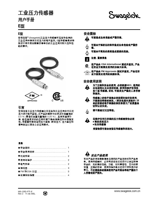
MS-CRD-PTI-ERev 2 11-08-WEL工业压力传感器用户手册 E 型E 型世伟洛克® (Swagelok)工业压力传感器可在各种各样的工业应用中提供系统压力的电子监测。
E 型传感器是被特殊设计用于满足需要防爆等级的工业应用对耐久性和性能的要求。
®引言世伟洛克工业压力传感器允许在各种工业应用中对系统压力进行电子监控。
该产品的精度为极限点校准量程的 0.5 %(最佳拟合直线量程的 0.25 %),且拥有温度补偿,能在温度波动的应用环境下确保准确性和长期稳定性。
传感器可提供各种压力连接,额定压力,压力单位和信号输出以满足众多应用需求。
■ 安全图标 ............................. 1■ 安全使用说明 ......................... 1■ 机械安装 ............................. 2■ 使用与维护 ........................... 2■ 电气安装 ............................. 2■ 接线图............................... 3■ FM 和CSA 认证 ....................... 3■ 故障排除指南 . (4)目录可能造成生命危险或严重伤害。
可能由于弹射出的部件造成生命危险或严重伤害。
可能由于高热的表面造成燃烧的危险。
注意,重要信息该产品由 CSA International 测试并鉴定。
产品在安全方面满足适用的加拿大标准。
该产品由FM Approvals 测试并鉴定。
产品在安全方面满足适用的美国标准。
警告警告警告安全图标为了正确和安全的使用,必须根据NEC 、适用的本地规范以及本说明安装、使用和维护世伟洛克 E 型 传感器。
否则,可能发生严重的人身伤害和损失。
传感器上的电子连接必须按照初始状态使用,不能添加旁路或修改。
世伟洛克 SK系列 多用途球阀 说明书

A-76 球阀A多用途球阀SK 系列■ 工作压力可达 6000 psig (413 bar)■ 温度范围从−40 到 150°C (−40 到 302°F)■ 使用紧凑型设计提供大流量能力■ 1/4 至 3/8 in. 和 6 至 8 mm 端接■ 316不锈钢结构SK 系列球阀 A-77A弹簧加载的■ ■ 漏密封压力—温度额定值可供应低温 SK 系列球阀。
见第 P A-79 页。
世伟洛克® (Swagelok ®) SK 系列球阀采用紧凑型设计、具有扭矩低、四分之一圈操作的特点、能够在压力最高达 6000 psig (413 bar) 的应用场合提供可靠关断。
其它特点还有:■ 流量系数 (C v ) 0.9 到 1.4■ 世伟洛克可测量卡套管接头、NPT 和 ISO 公称管以及世伟洛克外螺纹 VCO ®端接■ 标准面板安装 ■ 双向流动■ 可以使用密封成套件进行现场组装特点有关世伟洛克球阀的重要说明世伟洛克球阀设计用于全开或全闭位置。
在一段时间内未使用的阀门可能会有较高的初始启动力矩。
测试所有世伟洛克 SK 系列球阀都在工厂使用氮气在 1000 psig(69 bar) 的压力下进行了双流向测试。
阀座的最大容许泄漏率为0.1 std cm 3/min 。
壳体测试时要求用检漏液检测不到泄漏。
O 型圈阀杆密封■ ■ 清洁和包装所有世伟洛克 SK 系列球阀都是按照世伟洛克标准清洁和包装规范 (SC-10)、MS-06-62 清洁和包装的。
按照世伟洛克特殊清洁和包装 (SC-11)、 MS-06-63 进行的特殊清洁和包装作为可选项提供、以确保符合 ASTM G93 等级 C 中所规定的产品清洁度要求。
参阅第 P A-83 页的工艺选项。
卡套管数据、P G-5。
带有 VCO 管接头端接的阀的额定压力是基于与之配合的管 接头的额定值;见世伟洛克产品目录 VCO O 型圈面密封接头、P B-135。
swagelok 样本气瓶,配件和停工管 2说明书

Sam ple Cylinders, Accessories, and Outage TubesFeatures■ Sizes from 10 to 3785 cm3 (1 gal)■ Working pressures up to 5000 psig (344 bar)■ 304L and 316L stainless steel and alloy 4002 Sample Cylinders, Accessories, and Outage TubesDouble-Ended Cylinders■ Sizes from 40 to 3785 cm 3 (1 gal)■ Working pressures up to 5000 psig (344 bar)■ 304L and 316L stainless steel materials resist intergranularcorrosion.■ 304L and 316L stainless steel double-ended cylinders areavailable with dual certifi cation to DOT and TC requirements.TestingEach DOT cylinder is hydrostatically tested to at least 5/3 theworking pressure. All testing of DOT cylinders is witnessed by a DOT-approved independent inspection agency.DOT-3E 1800/TC-3EM 124 cylinders are hydrostatically proof tested at 3050 psig (210 bar). One cylinder of each lot is burst tested.DOT-3A 1800 and 5000/TC-3ASM 124 and 344 cylinders are marked with a serial number. Volumetric expansion of each cylinder during hydrostatic testing must be within the limits set by DOT Specifi cation 3A and TC Specifi cation 3ASM. D OT-3A 1800/TC-3ASM 124 cylinders are hydrostatically proof tested at 3000 psig (206 bar) minimum. D OT-3A 5000/TC-3ASM 344 cylinders are hydrostatically proof tested at 8500 psig (586 bar) minimum.DOT-SP7458 1800 cylinders are hydrostatically proof tested at 3000 psig (206 bar).ƽ I t is the responsibility of the party fi lling the cylinder tohave it retested by an approved facility, at the requiredintervals, in accordance with DOT and TC regulations.Features■ Body made of seamless tubing provides consistent wallthickness, size, and capacity.■ Smooth internal neck transition allows easy cleaning andeliminates trapped fl uids.■ Cold-formed female NPT threads provide greater strength.■ Heavy-wall end connections provide strength andresist fl aring.■ Full-penetration gas tungsten arc-weld constructionprovides leak-tight sample containment.■ S w agelok ® DOT sample cylinders conform to 49 CFR Part178, “Specifi cations for Packagings.”■ Swagelok Transport Canada (TC) sample cylinders conformto CAN/CSA B339, “Cylinders, Spheres, and Tubes for theTransportation of Dangerous Goods.”Single-Ended Cylinders■ 150, 300, and 500 cm 3 sizes meeta variety of sampling needs.■ 304L stainless steel constructionresists intergranular corrosion.TestingDOT-4B 500 cylinders are hydrostatically proof tested at 1000 psig (69 bar) minimum.Pressure-Temperature RatingsRatings up to 100°F (37°C) are determined by DOT code. Ratings limited to 300°F (148°C) max with PTFE internal coating. Ratings may be limited by individual country government regulations.Sample CylindersTransportable Pressure Equipment Directive (TPED)The Transportable Pressure Equipment Directive (TPED) provides requirements relating to the design, manufacture, and testing of transportable pressure vessels and accessories, including sample cylinders and rupture discs. The intent of the directive is to provide a uniform level of product safety throughout the European Union countries.For information about TPED-compliant Swagelok products, see the Swagelok Products Compliant with the Transportable Pressure Equipment Directive catalog, MS-02-193.Sample Cylinders, Accessories, and Outage Tubes 3Ordering Information, Technical Data, and DimensionsSelect an ordering number.Dimensions are for reference only and are subject to change.Single-Ended CylindersDouble-Ended CylindersSample Cylinders4 Sample Cylinders, Accessories, and Outage TubesOverpressure ProtectionCompressed gas cylinders must be equipped with pressure relief devices in accordance with United States DOTregulations and CGA S-1.1. The CGA standard lists devices that can be used with specifi c gases. It also contains information on other types of pressure relief devices.ƽ B e sure to use the correct pressure-relief device for the gas being used.ƽ Proper fi lling of the cylinder according to DOTspecifi cations, or other local regulations, is criticalin preventing overpressurization.Rupture Disc UnitsSwagelok rupture disc units pro t ectsample cylinders from overpressurizationby venting the cylinder contents toatmosphere. The rupture disc is welded toa body that is threaded into a valve bodyor a rupture disc tee and sealed by an elastomer O-ring. Therupture disc can be easily replaced without removing thevalve or the tee from the cylinder.Nonrotating-Stem Needle Valves with Rupture Disc UnitsRupture Disc TeesThese compact assemblies are designed for use with various Swagelok valves. Tees are made of 316 stainless steel. Eachtee includes a rupture disc unit.Rupture Disc Precautions1. D o not use rupture disc devices in a location where the release of the cylinder contents might create a hazard. The rupture disc vents to the atmosphere through six radial holes in the body. Pressure is released suddenly with a loud noise, and gases escape at high velocity.2. K now the burst pressure. (This rating is marked on theend face of the rupture disc unit, as required by CGAS-1.1.)3. B e sure the maximum burst pressure does not exceed the cylinder test pressure.4. B e sure the minimum burst pressure is at least 40 % higher than the cylinder fi lling pressure.5. I nspect rupture discs regularly. The strength of rupture discs deteriorates with time due to temperature, corrosion, and fatigue. Pulsating pressure, vacuum/pressure cycling, heat, and corrosive fl uids and atmospheres can reduce the disc’s burst pressure.6. D o not use rupture discs to protect vessels with volumes greater than 3 gal (11 355 cm 3) for compressed gases or 1 1/2 gal (5677 cm 3) for liquefi ed gases.7. P rovide suitable means to isolate the sample cylinderfrom the system in case the rupture disc bursts whiletaking a sample.8. I n cylinders with liquefi ed gases, a small temperatureincrease during transportation or storage will causethe liquid to expand and may cause the rupture diskto release its contents. See local regulations and otherappropriate guidelines for safe fi lling limits for yourapplication.Ordering Information and DimensionsDimensions are for reference only and are subject to change.Dimensions are for reference only and are subject to change.For more information, see the Swagelok Nonrotating-Stem Needle Valves catalog, MS-01-42. Other Swagelok valves are available for use with sample cylinders. Contact your authorizedSwagelok sales and service representative for details.Ordering Information and DimensionsOrdering InformationMaterials of Construction O-ring Fluorocarbon MSample Cylinders, Accessories, and Outage Tubes 5PTFE CoatingInternal cylinder surfaces can be coated with PTFE to providea nonstick surface, which aids in cleaning. To order, add -T to the cylinder ordering number.Example: 304L-HDF4-300-TElectropolishingElectropolishing provides a clean internal surface with ahigh degree of passivation. To order, add -EP to the cylinder ordering number.Example: 304L-HDF4-300-EPAdditional MarkingCylinders can be furnished roll stamped or laser etched to meet specifi c identifi cation requirements, such as company name, address, serial number, or order number. Swagelok will not mark cylinders with the intended contents.Roll Stamping—To order, add -RS to the cylinder ordering number, followed by the specifi c information.Example: 304L-HDF4-300-RS Company Name and Address DOT-3E, -4B, and -SP7458 cylinders are roll stamped on the cylinder wall. DOT-3A cylinders are roll stamped on the crown.Laser Etching—To order, add -LE to the cylinder ordering number, followed by the specifi c information.Example: 304L-HDF4-300-LE Company Name and Address This information will be laser etched on the cylinder wall.Cylinders with the above options conform to DOT specifi cations.End CapsEnd caps protect valves from damage. Each cap threads onto a neck ring that has been peened to the cylinder neck. End caps are made from plated carbon steel and areavailable for use on 2250 and 3785 cm 3 (1 gal) cylinders. Swagelok angle-pattern valves canbe used on cylinders with end caps.To order, add C to the cylinder ordering number.Caps and PlugsCaps and plugs protect Swagelok tube fi tting or NPT endconnections on valves during cylinder transport. Contact your authorized Swagelok representative for details.Tube fittingplugPipe plugPipe capCustomer-suppliedring shownNeck ringEnd capAccessoriesCarrying HandleThis accessory provides a convenient way to carry sample cylinders.The handle is made from 304 stainless steel and is available for use on 400 cm 3 and larger cylinders, as well as 300 cm 3 cylinders rated to 5000 psig (344 bar).To order a sample cylinder to be shipped with a carrying handle, add Hto the cylinder ordering number.Example: 304L-HDF4-300HTo order a carrying handle as a separate component, use one of the following ordering numbers:To order a 2250 or 3785 cm 3 (1 gal) sample cylinder withfactory-assembled end caps and neck rings to be shipped with a carrying handle, add CH to the cylinder ordering number.Example: 304L- H DF8-2250CHOptions6 Sample Cylinders, Accessories, and Outage TubesOutage TubesTube LengthLOutage tubeadapterOutage tube length (L) is measured from the end of the pipefi tting to the end of the tube. Standard tube length is 10.4 in.(26.4 cm). Tubing can be cut to a desired length; instructionsare included.Outage tubewelded tomale NPT endOutage tubeSample Cylinders, Accessories, and Outage Tubes 7Ordering InformationAdapters with Outage TubesSelect an adapter ordering number. For alloy 400 material, replace SS with M.Example: M -DTM4-F4-104Nonrotating Stem Needle Valves with Outage Tubes Select a valve ordering number.For alloy 400 material, replace SS with M.Example: M -14DKM4-104Factory-Cut Tube Lengths Follow the example below to determine how to order outagetubes cut at the factory to a length other than 10.4 in. (26.4 cm).Sample cylinder ordering number is 304L-HDF4-150.Outage required is 30 %.See Outage Tube Lengths table at right:1. Find 304L-HDF4-150, the cylinder ordering number.2. Read across to the 30 % column.3. Tube length is 1.79 in.4. Designator is 018.5. R eplace 104 in the outage tube adapter or valve ordering number with 018.Examples: S S-DTM4-F4-018SS-16DKM4-F4-018ƽC aution:Tolerances on cylinder volume, dimensions, andthread fi t can change the outage obtained by asmuch as 20 %. To obtain an exact outage, each outage tube and cylinder assembly should becalibrated by a suitable method.Valves do not include rupture disc units. Contact your authorized Swagelok representative for information about valves with outage tubes and rupturedisc units.Outage Tube LengthsOutage TubesSafe Product SelectionWhen selecting a product, the total system design must be considered to ensure safe, trouble-free performance.Function, material compatibility, adequate ratings,proper installation, operation, and maintenance are the responsibilities of the system designer and user.Warranty InformationSwagelok products are backed by The Swagelok Limited Lifetime Warranty. For a copy, visit or contact your authorized Swagelok representative.Miniature Sample CylindersMiniature sample cylinders with 3/8 in. Swagelok tube adapter end connections allow transport of low volumes of fl uids. The tube adapter ends can be connected to 3/8 in. Swagelok tube fi ttings or welded to 1/4 or 3/8 in. tubing.Features■ S ingle-ended or double-ended designs■ Corrosion-resistant 316 stainless steel construction ■ P ressure rating of 1000 psig (68.9 bar)■ Sizes include 10, 25, and 50 cm 3 capacities ■ Smooth internal port transition for easy cleaning ■ Volume is closely controlled■ Full-penetration butt weld constructionCleaning and TestingEvery miniature sample cylinder is cleaned in accordance withSwagelok Special Cleaning and Packaging (SC-11), MS-06-63.Every miniature sample cylinder is proof tested at 1667 psig (114 bar) with dry nitrogen gas.Oxygen Service HazardsFor more information about hazards and risks of oxygen-enriched systems, see the Swagelok Oxygen System Safety technical report, MS-06-13.Ordering Information and DimensionsSelect an ordering number.Dimensions, in inches (millimeters), are for reference only and are subject to change.Swagelok—TM Swagelok Company© 2001, 2003, 2004, 2005, 2007 Swagelok Company Printed in U.S.A., MI October 2007, R4MS-01-177(9.5)1/4 ID for tube socket weld connectionAExisting DOT and TC specifications do not cover miniature cylinders of this size, construction, and pressure rating.N Series Needle ValvesSwagelok N series severe-service union-bonnet needle valves can handle working pressures up to 6000 psig (413 bar) and are available in straight and angle patterns.For more information, see the Swagelok Severe-Service Union-Bonnet NeedleValves—N Series and HN Series catalog, MS-01-168.Quick-ConnectsSwagelok quick-connects are available in single- and double-end shutoff stem models and can be keyed to prevent accidental intermixing of different lines in multifl uid or multipressure systems.For more information, see the Swagelok Quick-Connects catalog, MS-01-138.Additional Products。
swagelok

(38.9)
1.53
(63.5)
2.50
25/32 面板孔
(19.8)
0.19 (4.8) 最大面板 厚度
SWAGELOK
B A
所示尺寸是世伟洛克卡套管接头螺母用手指旋紧时的尺寸。 ➀ 可订购带有两种不同端接的 SK 系列阀。 关于订购信息可与您当地授权的世伟洛克公司代表联系。 ➁ 参阅规范 ISO 7/1、 BS EN 10226-1, DIN-2999 和 JIS B0203。 ➂ 标准阀门上的 VCO 接头包括低温碳氟化合物 FKM O-型圈。
316 SS / A479 PTFE 基 具有烃粘合剂涂层的二硫化钼
13 15 18
订购信息与尺寸
选择一个订购号。 以 in. (mm) 为单位表示的尺寸仅供参考, 可能有变动。
端接➀ 类型 世伟洛克 卡套管接头 内螺纹 NPT 内螺纹 ISO➁ 外螺纹 NPT 外螺纹 VCO 接头➂ 尺寸 1/4 in. 3/8 in. 6 mm 8 mm 1/4 in. 1/4 in. 1/4 in. 1/4 in. 订购号 SS-4SKPS4 SS-4SKPS6 SS-4SKPS6MM SS-4SKPS8MM SS-4SKPF4 SS-4SKPF4RT SS-4SKPM4 SS-4SKPVCO4 Cv 1.3 1.4 1.3 1.3 1.2 1.2 1.1 0.9 0.188 (4.8) 孔径 尺寸, in. (mm) A 3.60 (91.4) 3.73 (94.7) 3.60 (91.4) 3.68 (93.5) 2.91 (73.9) 2.91 (73.9) 3.23 (82.0) 3.15 (80.0) B 1.80 (45.7) 1.86 (47.2) 1.80 (45.7) 1.84 (46.7) 1.46 (37.1) 1.46 (37.1) 1.62 (41.1) 1.58 (40.1)
swagelok工具手册
工具和附件
台式弯管机
特点
■ 牢固、 轻量的铝制结构 ■ 弯曲范围 1 至 180° ■ 卡套管外径范围为 1/4 至 1 1/4 in. (0.028 至 0.120 in.
壁厚) 和 12 至 30 mm 外径 (1.0 至 3.0 mm 壁厚)
■ 钢制弯管架槽需装配: ■ 壁厚超过 0.095 in. 的外径为 1 in. 的卡套管 ■ 壁厚超过 2.4 mm 外径为 25 mm 的卡套管 ■ 所有尺寸的 SAF 2507™ 卡套管 ■ 所有尺寸的厚壁退火不锈钢卡套管 ■ 所有尺寸的冷拔 1/8 硬度的不锈钢无缝卡套管 ■ 包含有加油枪和用于存放的金属手提箱 ■ 可以使用可选的扭矩离合器和支撑臂用一个 1/2 in. 手动式
电动弯管机
特点
■ 电动控制 ■ 弯曲范围 1 至 110° ■ 卡套管外径范围为 1 至 2 in. 外径
预装器
多头液压式 . . . . . . . . . . . . . . .
气动液压式 . . . . . . . . . . . . . . . 预装工具 . . . . . . . . . . . . . . . . . 间隙检测规 . . . . . . . . . . . . . . . 深度标记工具 . . . . . . . . . . . . . 5 6 6 7 7
电线型号 AWG/ SJT
电源线代号 1 2 3 4 5
-FKIT -MKIT
日本/台湾
英国
220/240 V (ac) NEMA 50/60 Hz L6-20 110/120 V (ac) IEC-309 50/60 Hz 220/240 V (ac) BS 1363 50/60 Hz 220/240 V (ac) CEE 7/7 50/60 Hz 220/240 V (ac) AS 3112 50/60 Hz
世伟洛克 LD 系列 隔膜阀 说明书
LD 系列隔膜阀 A-205A 隔膜阀LD 系列■ 工作压力高达 300 psig (20.6 bar)■ 开关、散装气体分配以及隔离服务■ 铸造、锻造及棒材不锈钢阀体材料■ 1/4 至 1 in.、12 至 25 mm 端接A-206 隔膜密封阀A可换隔膜/阀杆组件焊接隔膜结构■ 隔膜焊接到阀杆上、以防泄漏。
■ 三个隔膜实现强度、柔性和循环寿命的优化组合。
■ 设计实现流体的全金属包容。
独特的阀杆头设计■ PCTFE 阀杆头镶块有利于无泄漏的关闭。
■ 补偿阀杆头有助于防止由于过度紧固而造成的损坏。
特点■ 润湿区域无弹簧或螺纹、从而操作更加清洁。
■ 成型流道实现大流量。
■ 加固的隔膜设计实现有效的阀杆缩回。
联合阀帽的设计 可防止意外拆卸上部阀杆的位置显示阀门处于 开启还是关闭状态加固的隔膜实现有效的 阀杆缩回尺寸为 1/2 in. 尺寸为 1 in.阀体结构铸造 (尺寸为 1/2 和 1 in.)■ 阀体上机加工润湿表面的粗糙度 R a 平均为 20 µin. (0.51 µm)。
■ 提供可选的电抛光阀体外表面 (ELD 系列)。
■ 提供可选的内表面电抛光至粗糙度 R a 平均为 10 µin.(0.25 µm) 延长管。
锻造 (尺寸为 1/2 in.)■ 此种设计尺寸小、内部容积更少。
■ 润湿表面电抛光至 R a 平均为 5 µin. (0.13 µm)。
棒材 (尺寸为 1/2 和 1 in.)■ 阀门和管状组合成一个整体的、紧凑的部件。
■ 块式阀体实现散装气体系统的紧凑布局。
■ 润湿表面电抛光至 R a 平均为 5 µin. (0.13 µm)。
独特的夹环设计延长了循环寿命开启关闭关闭PCTFE 镶块LD 系列隔膜阀 A-207A1234567810119a9b9c9d 9e 9f9结构材料测试SC-11 工艺每个按照世伟洛克® (Swagelok ®) 特殊清洁及包装 (SC-11)、MS-06-63 进行处理的 LD 系列隔膜阀均进行了最大泄漏率为 4 3 10–9 std cm 3/s 的氦检漏测试。
阀门swagelok
漏、 并促进变送器的精确读数。
在阀门的使用期限内可要求作填料的调整。 尚未经过一段时间循环的阀、可有较高的初始致动力距。
仪表阀组 V、 VB 和 VL 系列
A-249
阀门特点
通过世伟洛克阀组的流量、 由一系列不锈钢针阀加以控制、 每一 阀门具体的功能 — 阻断压力、 放掉压力或平衡压力 — 视其在 阀组上的位置而定。 所有这些功能的控制、 由两种针阀设计来分担 — 大阀盖针阀适 用于 0.156 in. (4.0 mm) 通径的阀组、 小阀盖针阀适用于 0.125 in. (3.2 mm) 通径的阀组。 在两种设计上、 阀杆填料在开启或关闭位置从外面可加以调整 PTFE 是标准填料、 也可供应 Grafoil 填料供高温用途使用。
淬硬不锈钢、 无旋转球头 提供稳定的关闭
技术数据
孔规格 (截止阀) 0.125 in. (3.2 mm) 对于所有 2阀 V 系列 0.156 in. (4.0 mm) 对所有其它 2 阀: 2.0 至 3.5 lb (0.9 至 1.6 kg) 重量 3 阀: 3.2 至 6.4 lb (1.5 至 2.9 kg) 5 阀: 6.0 至 8.0 lb (2.7 至 3.6 kg)
阀组特点 . . . . . . . . . . . . . . . A-248 阀门特点 . . . . . . . . . . . . . . . A-249 技术数据 . . . . . . . . . . . . . . . A-249 测试 . . . . . . . . . . . . . . . . . . A-249
大阀盖阀
小阀盖阀
不锈钢手柄有 “支点”定位 螺钉防止因振 动而松开 填料螺栓、 可作阀杆填料调整 轧制的阀杆螺纹、 延长使用寿命 PTFE 填料在 阀杆螺纹下面、 将螺纹与系统流体隔开 全开位时产生安全的背密 封、提供阀杆的辅助密封
swagelok安全阀
比例卸荷阀
技术数据
压力 — 温度额定值
系列 工作压力 20°C (70°F) 设定压力➀ 出口压力➁ 碳氟 FKM R3A 6000 psig (413 bar); 卸荷期间高达 8000 psig (551 bar) 50 至 6000 psig (3.4 至 413 bar) 1500 psig (103 bar) 丁腈 橡胶 氯丁 橡胶 乙烯 丙烯 碳氟 FKM R4 6000 psig (413 bar) 50 至 1500 psig (3.4 至 103 bar) 2500 psig (172 bar) 丁腈 橡胶 氯丁 橡胶 乙烯 丙烯 碳氟 FKM RL3 和 RL4 300 psig (20.6 bar) 10 至 225 psig (0.68 至 15.5 bar) 225 psig (15.5 bar) 丁腈 橡胶 氯丁 橡胶 — 乙烯 丙烯
仅
4 阀座 15 垫片
碳氟 FKM-粘结➀ 316 SS/A479
316 SS/A479 PTFE 涂层 316 SS/A240 316 SS/A479
12 13 14 15
19
12 16 17 18
8
16 阀座护圈 17 O 型圈 18 插入件 19 阀体
压力降, bar
压力降, psi
设定压力 550 psig (37.8 bar)
压力降, bar
压力降, psi
2600 psig (179 bar)
进口压力, bar
设定压力 2600 psig (179 bar)
压力降, bar
压力降, psi
压力降, bar
压力降, psi
比例卸荷阀
尺寸
- 1、下载文档前请自行甄别文档内容的完整性,平台不提供额外的编辑、内容补充、找答案等附加服务。
- 2、"仅部分预览"的文档,不可在线预览部分如存在完整性等问题,可反馈申请退款(可完整预览的文档不适用该条件!)。
- 3、如文档侵犯您的权益,请联系客服反馈,我们会尽快为您处理(人工客服工作时间:9:00-18:30)。
SNOOP® 2006年1月1. 产品确认
SNOOP®: 检漏液仅用于外部表面。
最佳使用温度在-3℃和 93℃(27℉和 200℉) 之间。
制造商:
紧急联系人:
世伟洛克公司Chemtrec (800) 424-9300
29495 F.A. Lennon Dr.
Solon, Ohio 44139
电话: (440) 349-5600
2. 成分
成分CAS # WT% PEL
水7732-18-5 >95 无适用数据表面活性剂无适用数据<5 无适用数据
3. 危害健康信息
•欧共体危险小组..............................................无.
•对人或环境所造成的特殊危险......................无
•LC50/LD50 ........................................................无适用数据
侵入途径
皮肤接触皮肤吸收眼睛接触吸入食入否否是否是
4. 急救措施
•如果吸入 (过度): 不可能被吸入。
•与皮肤接触之后 (过度): 用肥皂和水进行彻底清洗。
如果产生了强烈的刺激,
请寻求医护人员的帮助。
•误入眼睛之后: 用水彻底清洗15分钟,请寻求医护人员的帮助。
不要用手揉眼睛。
•如果吞入: 不可能引起疾病,如果有必要请寻求医护人员的帮助。
•医学资料: 未知。
SNOOP® 2006年1月5. 防火措施
•合适的灭火剂: 不适用。
.
•不合适的灭火剂: 尚无。
•由材质或准备工作自身, 尚无。
由产品燃烧或所形成的气体
引起的特殊危险
无。
•其它信息:
自燃UEL LEL 敏感性无适用数据无适用数据无适用数据无适用数据
6. 意外事故预防措施
•人员保护措施: 在必要时对眼睛和手进行保护可以将过度曝露的危险降到最低。
•环境保护措施: 不需要。
•清洁措施: 使用具有良好吸附性的材料清洁溅出的液体。
•其它信息: 无。
7. 处理和储存
•安全信息: 无。
•防火防爆方面的保护信息: 无。
•其它信息: 储存在一个冷却且干燥的环境中以便使产品的性能达到最优化。
8. 曝露控制和人员保护
•保护人员的预防措施: 不需要。
•呼吸保护: 不需要。
•手部保护: 建议使用橡胶手套以便将曝露程度降到最低。
•眼睛保护: 由于SNOOP® 检漏液可能会溅入眼睛,建议戴眼镜。
•皮肤保护: 使用后请洗手。
9. 物理和化学特性
外观气味pH 密度蒸汽压力无色液体无味 6.75 +/- 0.75 1.0 gm/cm3无适用数据沸点溶点闪点可燃性爆炸性212°F/100°C 无适用数据无适用数据无适用数据无适用数据
SNOOP® 2006年1月10. 稳定性和活化性
•要避免的情况: 无。
•要避免的材料: 强氧化剂, 碱金属, 和与水产生放热反应的化合物。
•危险的可溶解产品: 无。
11. 毒性信息
•急性毒性特征: 尚无。
•对健康的影响: 尚无。
•其它对健康的影响: 尚无。
敏感性致畸性生殖毒性诱变性有相互作用的
产品致癌性
无适用数据无适用数据无适用数据无适用数据无适用数据根据NTP,
IARC 和OSHA
,所列分没有致
癌性
12.生态信息
•活动性: 可与水相比。
•降解性: 尚无。
•有毒化学物质累积性:尚无各种生物体内积累或生物放大影响。
•在毒性方面的短/长期影响:尚无生态影响。
13. 废品处理
•对于废品的处理方法: 在美国尚未使用的产品不被认作有毒废物。
以合理方式处理废品。
•欧共体 (EC)的意见 : 根据成分使用合适的废品代号。
14. 运输信息
•运输预防措施: 当运输此产品时,请对适用规定进行咨询。
•其它信息: 无。
SNOOP® 2006年1月15. 法规信息
•欧共体规定: 根据化学成分,此产品已经被归类到CHIP-96 规定下。
•美国/加拿大规定列表: SARA 313 – 否, 加拿大受控产品- 否, TSCA – 是。
•欧共体相关风险规定: 无。
•欧共体相关安全规定: S: 37/39 – 戴合适的手套及眼睛/面部保护装置。
S: 20 – 当使用时不要食入或喝入。
•其它信息: 对于特殊要求请咨询国家编码。
16. 其它信息
•想了解更多信息请联系: 您的世伟洛克经销商或列在此表第一部分中的联系人。
•用于此编撰文件的信息来源此文件中包含所使用的每一种成分的特性。
此材料安全数据表的
设计目的是为经销商及用户以负责任的态度提供SNOOP®
产品的信息及处理和使用方式。
数据准备由
环境和安全部门(440) 349-5955 2006年1月。